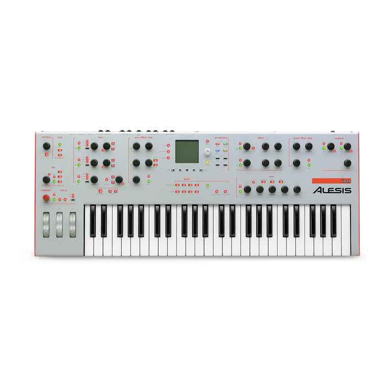
Alesis Ion User manual

8-Voice Analog Modeling Synthesizer
Quick Start Owner’s Manual
(ENGLISH)
BOX CONTENTS
•SYNTHESIZER
•POWER CABLE
Manual de inicio rápido para el usuario
(ESPAÑOL)
CONTENIDO DE LA CAJA
•SINTETIZADOR
•CABLE DE ALIMENTACIÓN
Schnellbedienungsanleitung
(DEUTSCH)
INHALT DER VERPACKUNG
•SYNTHESIZER
•
N
ETZKABEL
Manuel d’utilisation du propriétaire
(FRANÇAIS)
CONTENU DE LA BOÎTE
•SYNTHÉTISEUR
•CÂBLE D’ALIMENTATION
Manuale rapido di utilizzazione
(ITALIANO)
CONTENUTO DELLA CONFEZIONE
•SINTETIZZATORE
•CAVO DI ALIMENTAZIONE

This page intentionally left blank.

ION QUICK START OWNERS MANUAL
(ENGLISH)
Connection Diagram
Connecting AC Power
Before making any power connections, make sure the Ion’s power switch
is turned off.
1. Plug the female end of the power cable into the Ion’s
power socket.
2. Plug the male (plug) end into a properly grounded power outlet.
Making Audio Connections
•Stereo. Connect two cables from the Ion’s left and right outputs to
two inputs of an amp or mixer.
•Headphones. Plug a set of headphones into the headphone jack on
the rear panel.
1

Connecting the Foot Pedals
• (sust pedal) is designed to work with any standard momentary
footswitch. The Ion will calibrate itself to a normally open or normally
closed pedal if the pedal is plugged in when the Ion is powered on.
• (exp pedal) is designed to work with a Roland EV-5 pedal or
equivalent.
The display
The Liquid Crystal Display (LCD) is at the center of the Ion in more ways
than one. Depending on the button or knob you’ve activated, it may
show the program name, which Programs are used in a Setup, the values
of the parameters being edited, or even a graphic representation of a
waveform or an envelope.
The Home page
This is the screen that shows you the most different kinds of information
all at once. If you’re not already there, press the [home] button and
you’ll see something like this:
Here’s what each area of the Home screen means:
•The darkened bar at the top of the screen shows you the name of
the section being displayed. In this case, it reads home.
•Immediately below that are the bank and program number.
2

3
•Roughly in the middle you see the program name of the active
Part.
•The fourth line from the bottom shows the Setup number.
•Below that, the outlined rectangle shows the current Setup name.
•The “e box” icons to the right of the Program and Setup numbers
indicate that the Program and Setup have been edited, respectively.
•The filled rectangle on the second line from the bottom shows
which of the four Parts has been selected with the [panel active]
buttons.
Note: the icon on the inside left of this box indicates that the current
Part has been muted.
•The “quarter note” icon, the “equal to” sign (=) and the numbers to
its right tell you what the tempo setting is for the Setup.
•The “G” to the right of the tempo value indicates the setting of the
Global mode parameter tempo source. If the “G” is there, that
means the tempo source parameter is set to global. This causes the
tempo to remain the same when you recall a new Setup or change
Programs. If the “G” is not there, the tempo source parameter is set
to program. In this case, the tempo value can change from one
Setup to the next, or when you call up another program in Part A.
•The “MIDI connector” icon and the number to its right indicate the
MIDI Channel of the currently selected Part.
The Edit pages
Any time a knob is moved or a button is pressed, the Ion enters Edit
mode and displays a screen with parameters related to that knob or
button. The appearances of the pages can vary quite a bit, but there are
some things they have in common:
There can be up to three parameters displayed on any page. If the
desired parameter does not have a front panel knob, select it using a Soft
button and turn the data knob to edit the value.
Sometimes there are several pages of parameters related to a given
function. You will know this is the case by looking on the bottom line of
the page, as in the example below:
The numbers at the bottom of the page tell you how many pages there
are, and which page you are on. In the above example, there are five
pages available, and you are on page 1. When more than one page is
available, you can navigate to the additional pages using the [page X]
and [Wpage] buttons. Note that the arrow in the left corner is “grayed
out.” That means that there are no more pages available in that direction.
The Global pages
•When the [global] button is pressed, the Ion will enter Global mode.
Select the desired parameter using a Soft button and turn the data
knob to edit the value. For a complete description of the Global
mode parameters, see Chapter 3 of your User Manual.
The Mod Matrix pages
•When the [mod matrix] button is pressed, the Ion will enter Edit
mode for the active Program and display parameters related to the
Mod Matrix. This is also where the Tracking Generator is found. For
a complete description of the Mod Matrix and the Tracking
Generator, see Chapter 6 of your User Manual.
4

5
LED functions
Two LEDs serve as “speed” indicators: the rate LED and the tempo LED.
The rate LED may blink at a different speed depending on which of
three functions has been selected in the LFO section: [lfo 1], [lfo 2], or
[s&h].
The mod LEDs indicate that an edit has been made in the Mod Matrix
that affects one or more of the parameters in the section where the mod
LED is lit. If it isn’t obvious at first which parameter is being “modded,”
press the [mod matrix] button and look at the lists of sources and
destinations. For more information on the Mod Matrix, see Chapter 6 of
your User Manual.
The loop LED is similar to the mod LEDs in that it indicates that the loop
parameter has been activated inside the selected envelope. More
information about looping the envelopes can be found on pages 71-72 of
your User Manual.
Button functions
[edit] buttons – A green LED indicates that an [edit] button has been
pressed. This means that a particular set of parameters is being shown in
the display for inspection and editing.
Selection buttons – Some buttons allow you to select between different
sets of parameters that share a common knob or set of knobs. For
example, the [lfo 1], [lfo 2], and [s&h] buttons determine which of those
three functions will be controlled by the rate knob, and also call up
parameters from that function in the display. Similarly, the [pitch/mod],
[filter], and [amp] buttons determine which of those three envelopes will
be controlled by the five knobs in the env section.
Parameter buttons – Other buttons edit or toggle the parameter under
their control: for example, the [mono/poly] button or the [octave]
buttons in the osc section. Other examples include the [porta] button,

6
which enables portamento, and the [waveform select] buttons, which
determine the waveform utilized by each oscillator.
Special cases
[tap tempo] button – This button allows you to match the speed of the
arpeggiator, an LFO, or other effects to the tempo of a song simply by
tapping the button in time to the music! The LED under the button
flashes to give you an idea of what the tempo setting is currently.
[transpose] and [octave] buttons – These three buttons control the
global transposition and octave shift of the Ion’s keyboard. The settings
will affect all programs and setups, as well as the MIDI note output.
Knob functions
volume knob – This is the red knob just above the Pitch wheel. It
controls the level of the main and headphone outputs. Note that this
control has no effect on the aux outputs.
tempo knob – This is the knob in the upper left corner of the Ion. It
controls the speed of any number of functions, most notably the
arpeggiator.
data knob – This is the clear knob to the right of the display. Use it for
fine-tuning your edits, or to edit a parameter that has no front-panel
knob. It is also used for selecting Programs and Setups.
Performance controls
The Ion gives you a number of expressive controls at your fingertips, in
addition to all of the knobs and buttons:
Velocity – The Ion’s keyboard will respond to differences in how hard
you play the keys. You can tailor-make the keyboard’s response to your

7
playing style by selecting one of the nine keyboard curves found on
Global mode page 1, Soft button 2.
(p) or Pitch Bend wheel – This wheel is normally assigned to bend the
pitch of one or more oscillators, but it may be used as a source in the
modulation matrix to control nearly any parameter.
(m1) wheel – This wheel usually adds vibrato, but it also may be used as
a source in the modulation matrix to control nearly any parameter.
(m2) wheel – This wheel usually sweeps the filter, but it also may be
used as a source in the modulation matrix to control nearly any
parameter.

8
This page intentionally left blank.

MANUAL DE INICIO RÁPIDO DEL USUARIO
(ESPAÑOL)
Diagrama de conexión
Conexión de la fuente de corriente alterna
Antes de realizar cualquier conexión eléctrica, asegúrese de que el
interruptor de alimentación de Ion está apagado.
1. Enchufe el extremo hembra del cable de alimentación a la toma de
corriente de Ion.
2. Enchufe el extremo macho (del enchufe) a una toma de corriente
conectada a tierra correctamente.
Conexiones de audio
•Estéreo. Conecte dos cables desde las salidas derecha e izquierda
de Ion a dos entradas de un amplificador o mezclador.
•Auriculares. Enchufe unos auriculares en el jack de auriculares
situado en el panel trasero.
9

Conexión de los pedales de pie
• Pedal con función «sustain».Está diseñado para trabajar con
cualquier interruptor de pie provisional estándar. El sintetizador Ion se
calibrará por sí solo con un pedal normalmente abierto o normalmente
cerrado si el pedal está enchufado cuando el sintetizador Ion esté
encendido.
• Pedal EXP. Está diseñado para funcionar con un pedal V-5 o
equivalente.
La pantalla
La pantalla de cristal líquido (LCD —Liquid Crystal Display—) está
colocado en el centro del sintetizador Ion de más de una manera.
Dependiendo del botón o perilla que usted haya activado, podría mostrar
el nombre del programa, qué programas se utilizan en un ajuste, los
valores de los parámetros que se están modificando o incluso una
representación gráfica de una forma de onda o un sobre.
La página de inicio
Esta es la pantalla que le muestra la información más variada de una sola
vez. Si aún no ha llegado a ella, pulse el botón [Home] y verá lo
siguiente:
He aquí el significado de cada una de las áreas de la pantalla de inicio
[Home]:
10

11
•La barra oscurecida en la parte superior de la pantalla le muestra el
nombre de la sección que está viendo en ese momento. En este
caso, se puede leer home (inicio).
•Justo debajo, se encuentran el número de banco y de programa.
•En el centro puede ver el nombre del programa de la parte activa.
•La cuarta línea empezando por abajo muestra el número de ajuste
[Setup].
•Debajo, el rectángulo marcado muestra el nombre actual del setup
(ajuste).
•Los iconos «e box» (caja e) a la derecha de los números de programa
y de ajuste indican que el programa y el ajuste han sido editados
respectivamente.
•El rectángulo rellenado en la segunda línea empezando desde abajo
muestra cual de las cuatro partes ha sido seleccionada con los
botones del panel activo [panel active].
Nota: El icono en la parte interior izquierda de este cuadro indica
que la parte actual ha sido puesta en «mute».
•El icono de la «nota negra», el símbolo de «equivalencia» (=) y los
números a su derecha le indican en qué nivel está el ajuste de
tempo para el ajuste.
•La «G» a la derecha del valor de tempo indica el ajuste de la fuente
de tempo del parámetro de modo Global. Si la «G» está allí, eso
significa que el parámetro de la fuente de tempo está configurado en
modo global. Esto causa que el tempo se mantenga igual cuando
usted accede a un nuevo ajuste (setup) o cambia de programas. Si la
«G» no está allí, el parámetro de la fuente de tempo está configurada
en modo programa. En este caso, el valor del tempo puede cambiar
de un ajuste a otro o cuando accede a otro programa en la parte A.
•El icono de «conector MIDI» y el número a su derecha indican el
Canal MIDI de la parte seleccionada.

Las páginas de edición [Edit]
Cuando se mueve una perilla o se pulsa un botón, Ion introduce el modo
de modificación y muestra una pantalla con parámetros relacionados con
esa perilla o botón. Las apariencias de las páginas pueden variar
bastantemente, pero tienen algunos rasgos en común:
Pueden visualizarse hasta tres parámetros en una página. Si el parámetro
deseado no tiene una perilla en el panel frontal, selecciónelo usando un
botón suave y gire la perilla de datos para editar el valor.
A veces existen varias páginas de parámetros relacionadas con una
función específica. Sabrá que se trata de ese caso mirando la última línea
de la página, como en el ejemplo siguiente:
Los números en la parte inferior de la página le indican cuántas páginas
hay y en qué página se encuentra. En el ejemplo anterior hay cinco
páginas disponibles y usted está en la página 1. Cuando hay más de una
página disponible, puede navegar por las páginas adicionales usando los
botones de [page X]y [Wpage]. Observe que la flecha en la esquina
izquierda está oscurecida. Esto significa que no hay más páginas
disponibles en esa dirección.
12

13
Las páginas globales
•Cuando se pulse el botón [global], el sintetizador Ion entrará en
modo Global. Seleccione el parámetro deseado usando un botón
suave y gire la perilla de datos para modificar el valor. Para ver una
descripción completa de los parámetros del modo Global, vea el
Capítulo 3 de su Manual de usuario.
Las páginas de matriz de modulación (Mod Matrix)
•Cuando se pulse el botón [Mod Matrix], Ion entrará en modo de
modificación [Edit] para el programa activo y los parámetros de
visualización relacionados con la matriz de modulación. Aquí es
también donde se encuentra el generador de barrido [Tracking
Generator]. Para una descripción completa de la matriz de
modulación y del generador de barrido, vea el Capítulo 6 de su
Manual de usuario.
Funciones del LED
Dos LED sirven como indicadores de velocidad: el LED de ritmo y el
LED de tempo. El LED puede parpadear a una velocidad diferente
dependiendo de cual de las tres funciones haya sido seleccionada en la
sección de LFO. [lfo 1], [lfo 2] ó [s&h].
Los LED de modulación indican que se ha hecho una modificación en
la matriz de modulación que afecta a uno o más parámetros en la sección
donde se enciende el LED de modulación. Si desde el comienzo no es
evidente qué parámetro se está siendo «modulado», presione el botón
[Mod Matrix] y mire la lista de fuentes y destinaciones. Para más
información sobre la matriz de modulación, vea el Capítulo 6 de su
Manual de usuario.
El LED «loop» es similar a los LED de modulación porque indica que el
parámetro del bucle ha sido activado dentro del sobre seleccionado.

14
Puede encontrar más información sobre los sobres de «looping» en las
páginas 71-72 de su Manual de usuario.
Funciones de los botones
Botones de modificación [Edit] – Un LED verde indica que un botón de
modificación [Edit] ha sido pulsado. Esto significa que un grupo
especificado de parámetros está siendo mostrado en la pantalla para que
usted los inspeccione y modifique.
Botones de selección – Algunos botones le permiten seleccionar entre
diferentes grupos de parámetros que comparten una perilla común o un
grupo de perillas. Por ejemplo, los botones de [lfo 1], [lfo 2] y [s&h]
determinan cuales de esas tres funciones serán controladas por la perilla
de ritmo y también acceden a parámetros de esa función en la pantalla.
De manera similar, los botones [Pitch/Mod], [Filter] (filtro) y [Amp]
determinan cuales de esos tres sobres serán controlados por las cinco
perillas en la sección de sobres [Env].
Botones de parámetros – Otros botones modifican o controlan el
parámetro bajo su control específico: por ejemplo, el botón [Mono/Poly]
o los botones [Octave] en la sección de «osc». Otros ejemplos incluyen el
botón [porta], que permite portamento, y los botones [Waveform
Select], que determinan la forma de onda utilizada por cada oscilador.
Casos especiales
Botón [Tap Tempo] – Este botón le permite igualar la velocidad del
arpegiador, un LFO, u otros efectos al tempo de una canción
simplemente pulsando el botón ¡al ritmo de la música! El LED debajo del
botón parpadea para darle una idea del ajuste de tempo actual.
Los botones [Transpose] y [Octave] – Estos tres botones controlan la
transposición global y el turno de octavas del teclado de Ion. Los ajustes
afectarán a todos los programas y ajustes y también a la salida de la nota
MIDI.

15
Funciones de las perillas
Perilla de volumen – Esta es la perilla roja justo encima de la rueda de
pitch. Controla el nivel de las salidas principales y de los auriculares.
Observe que este control no tiene efecto en las salidas auxiliares.
Perilla de tempo – Esta es la perilla en la esquina superior izquierda de
Ion. Controla la velocidad de cualquier número de funciones, más
notablemente el arpegiador.
Perilla de datos – Esta es la perilla transparente a la derecha de la
pantalla. Úsela para la sintonización de sus modificaciones o para
modificar un parámetro que no tiene perilla en el panel frontal. Se usa
también para seleccionar programas y ajustes.
Controles de funcionamiento
Ion le ofrece una serie de controles expresivos a su alcance, además de
todas las perillas y botones:
Velocidad [Velocity] – El teclado del sintetizador Ion responderá a las
diferencias en cuanto a la fuerza utilizada cuando toque las teclas. Puede
individualizar la respuesta del teclado para su estilo al tocar
seleccionando una de las nueve curvas del teclado que se encuentran en
el modo Global de la página 1, botón suave [Soft] 2.
(p) o rueda de flexión del pitch – Esta rueda es normalmente asignada a
la flexión del pitch (pitch bend) en uno o más osciladores, pero puede
usarse como una fuente en la matriz de modulación para controlar casi
cualquier parámetro.
Rueda (m1) – Esta rueda normalmente agrega vibrato, pero puede
también usarse como una fuente en la matriz de modulación para
controlar casi cualquier parámetro.

16
Rueda (m2) – Esta rueda normalmente pasa por el filtro, pero puede
también usarse como una fuente en la matriz de modulación para
controlar casi cualquier parámetro.

ION KURZBEDIENUNGSANLEITUNG
(DEUTSCH)
Schaltplan
Anschluss an das Stromnetz
Stellen Sie sicher, daß der Netzschalter des Ion ausgeschaltet ist, bevor
irgendwelche Stromanschlussarbeiten vorgenommen werden.
1. Stecken Sie die Buchse des Stromkabels in die Steckdose des Ion.
2. Stecken Sie den Stecker des Stromkabels in eine ordnungsgemäß
geerdete Stromquelle.
Audio-Anschlüsse
•Stereo. Schließen Sie zwei Kabel von den linken und rechten
Ausgängen des Ion an zwei Eingänge eines Verstärkers oder
Mischpults.
•Kopfhörer. Schließen Sie einen Kopfhörer in die Kopfhörerbuchse
an der Rückseite des Geräts an.
17

Anschluss der Fußpedale
• (sust pedal) wurde zur Verwendung mit jedem herkömmlichen
momentären Fußschalter entworfen. Der Ion gleicht sich einem
normalerweise offenen oder normalerweise geschlossenen Pedal an, falls
das Pedal dann angeschlossen wird, wenn der Ion eingeschaltet ist.
• (exp pedal) wurde zur Verwendung mit dem Roland EV-5-Pedal oder
einem gleichwertigen Pedal entworfen.
Die Anzeige
Die Flüssigkristallanzeige (LCD) ist auf vielfältige Art und Weise das
Zentrum des Ion. Abhängig davon, welche Taste oder Regler bedient
wurden, kann hier der Programmname, welche Programme bei der
Eingabe verwendet werden, die Werte der veränderten Parameter oder
sogar eine grafische Darstellung einer Wellenform oder eines Umschlags
angezeigt werden.
Die Startseite
Dies ist der Bildschirm, welcher Ihnen die verschiedensten Informationen
alle auf einmal anzeigt. Sollten Sie sich nicht bereits dort befinden,
drücken sie auf die [home]-Taste und Sie werden ungefähr das Folgende
sehen:
Hier ist erklärt, was jeder Bereich der Startseite bedeutet:
18
Other manuals for Ion
2
Table of contents
Languages:
Other Alesis Synthesizer manuals

Alesis
Alesis Vortex User manual

Alesis
Alesis VI25 User manual

Alesis
Alesis Vintage Synth Explorer QS7.1 Instruction manual

Alesis
Alesis Micron User manual

Alesis
Alesis Fusion User manual

Alesis
Alesis QS6 User manual

Alesis
Alesis Vintage Synth Explorer QS7.1 User manual

Alesis
Alesis ANDROMEDA A6 Assembly instructions

Alesis
Alesis qs6.1 Manual

Alesis
Alesis QSR User manual

Alesis
Alesis Fusion Technical document

Alesis
Alesis Ion Manual

Alesis
Alesis QS7 User manual

Alesis
Alesis QSR 64 User manual

Alesis
Alesis ANDROMEDA A6 Guide

Alesis
Alesis NanoSynth User manual

Alesis
Alesis QS6.2 User manual

Alesis
Alesis Fusion User manual

Alesis
Alesis VI49 User manual

Alesis
Alesis VI61 User manual