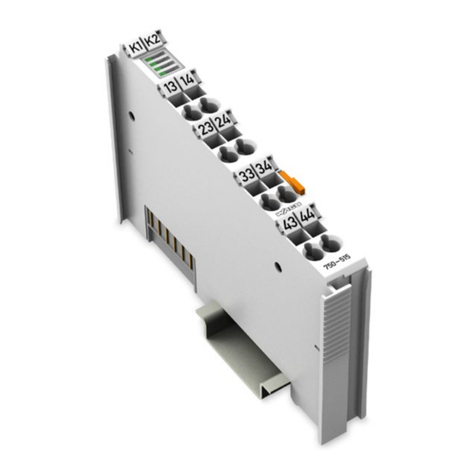
WAGO-I/O-SYSTEM 750 Table of Contents 3
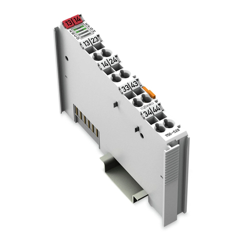
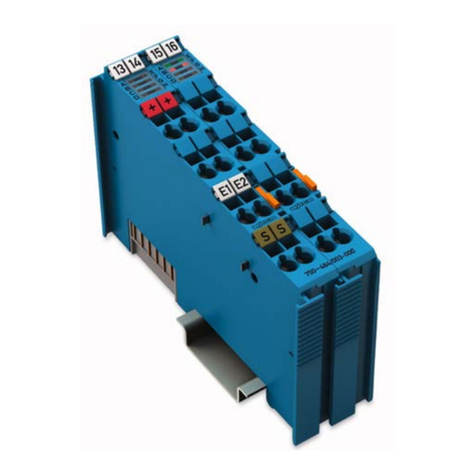
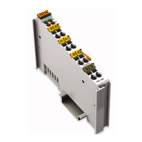
750-513 2DO 230V AC 2.0A/ Relay 2NO/ Potential Free
Manual
Version 1.2.2
Pos: 5 /D ok ume nt ati on al lg em ein /V erz eic h nis se /I nhal ts ver z eic hni s - Ü b er schr if t oG und Ver zei ch nis @ 3\mod_1219151230875_21.docx@21063 @ @ 1
Table of Contents
1Notes about this Documentation................................................................. 5
1.1 Validity of this Documentation................................................................. 5
1.2 Copyright................................................................................................... 5
1.3 Symbols..................................................................................................... 6
1.4 Number Notation....................................................................................... 8
1.5 Font Conventions ...................................................................................... 8
2Important Notes ........................................................................................... 9
2.1 Legal Bases ............................................................................................... 9
2.1.1 Subject to Changes ............................................................................... 9
2.1.2 Personnel Qualifications....................................................................... 9
2.1.3 Use of the WAGO-I/O-SYSTEM 750 in Compliance with
Underlying Provisions.......................................................................... 9
2.1.4 Technical Condition of Specified Devices......................................... 10
2.2 Safety Advice (Precautions).................................................................... 11
3Device Description ..................................................................................... 13
3.1 View ........................................................................................................ 15
3.2 Connectors............................................................................................... 16
3.2.1 Data Contacts/Internal Bus................................................................. 16
3.2.2 Power Jumper Contacts/Field Supply ................................................ 17
3.2.3 CAGE CLAMP®Connectors ............................................................. 18
3.3 Display Elements .................................................................................... 19
3.4 Schematic Diagram ................................................................................. 20
3.5 Technical Data ........................................................................................ 21
3.5.1 Device Data ........................................................................................ 21
3.5.2 Power Supply...................................................................................... 21
3.5.3 Communication .................................................................................. 21
3.5.4 Outputs ............................................................................................... 21
3.5.5 Connection Type ................................................................................ 22
3.5.6 Climatic Environmental Conditions................................................... 22
3.5.7 Load Limiting Value Graph of the Relay........................................... 23
3.6 Approvals ................................................................................................ 24
3.7 Standards and Guidelines........................................................................ 26
4Process Image ............................................................................................. 27
5Mounting..................................................................................................... 28
5.1 Mounting Sequence................................................................................. 28
5.2 Inserting and Removing Devices ............................................................ 29
5.2.1 Inserting the I/O Module .................................................................... 29
5.2.2 Removing the I/O Module.................................................................. 30
6Connect Devices ......................................................................................... 31
6.1 Connecting a Conductor to the CAGE CLAMP®................................... 31
6.2 Connection Examples.............................................................................. 33
6.2.1 1-Wire Connection, Protection Class I Actuators .............................. 33
6.2.2 1-Wire Connection, Protection Class II and III Actuators ................. 33
6.2.3 Operation of the Relays in Separate Circuits ..................................... 34
