manuals.online logo
Brands
  1. Home
  2. •
  3. Brands
  4. •
  5. Alfalaval
  6. •
  7. Industrial Equipment
  8. •
  9. Alfalaval HS-LA FILLER Manual

Alfalaval HS-LA FILLER Manual

Ver. 01
Original instructions
Operations & Maintenance Manual
HS-LA FILLER
Machine Serial No. : 2016-094
Project No. : 21R60.BA 0180
GENERAL INDEX
HS-LA FILLER_IM_E I
GENERAL INDEX
1 INTRODUCTION .................................................................................................1
1.1 WARNING ..................................................................................................................1
1.2 CHOICE AND QUALIFICATION OF THE OPERATOR.............................................2
1.2.1 GENERIC OPERATOR:......................................................................................2
1.2.2 MECHANICAL MAINTENANCE:.........................................................................2
1.2.3 ELECTRICAL MAINTENANCE:..........................................................................2
1.2.4 ALFA LAVAL TECHNICIAN: ................................................................................2
1.3 GUARANTEE.............................................................................................................3
1.3.1 SCOPE OF THE GUARANTEE ..........................................................................3
1.3.2 DURATION OF THE GUARANTEE ....................................................................3
1.3.3 APPLICATION OF THE GUARANTEE ...............................................................4
1.3.4 EXCLUSIONS AND LIMITS ................................................................................4
1.3.5 HOW TO RETURN THE DEFECTIVE MATERIAL..............................................4
1.4 TEST AND RESPONSIBILITY ..................................................................................5
1.5 SOFTWARE LICENCE ..............................................................................................6
1.6 TECHNICAL REFERENCE STANDARDS ................................................................7
2 GENERAL INFORMATION .................................................................................1
2.1 SAFETY .....................................................................................................................1
2.1.1 WARNINGS.........................................................................................................1
2.1.2 PERSONAL PROTECTIVE EQUIPMENT ..........................................................2
2.1.3 THE OPERATOR SHOULD ................................................................................4
2.1.4 THE OPERATOR SHOULD NEVER...................................................................4
2.1.5 THE OPERATOR SHOULD ALWAYS .................................................................5
2.1.6 DANGEROUS AREAS – WORKING AREAS ....................................................6
2.1.7 SAFETY SYMBOLS............................................................................................8
2.1.8 SAFETY SYMBOLS POSITION ....................................................................... 11
2.1.9 RESIDUAL RISKS DANGER SOURCE AREA .................................................26
2.1.10 IDENTIFICATION OF THE MACHINE ..............................................................31
GENERAL INDEX
HS-LA FILLER_IM_E
II
2.2 RECEPTION AND CONTROL OF THE MACHINE ................................................32
2.2.1 TRANSPORT ....................................................................................................32
2.2.2 ADOPTION OF PROTECTION DEVICES ........................................................34
2.2.3 PACKING OF THE MACHINE...................................................... 35
2.2.4 HANDLING AND LIFTING OF THE PACKING .................................................37
2.2.5 UNPACKING AND INITIAL INSPECTION.........................................................40
2.2.6 PACKAGING DISPOSAL ..................................................................................41
2.3 STOCKING / STORAGE..........................................................................................41
2.3.1 STORAGE BEFORE INSTALLATION...............................................................41
2.4 DEMOLITION AND DISPOSAL ..............................................................................42
2.4.1 INTRODUCTION...............................................................................................42
2.4.2 PROCEDURE ...................................................................................................43
2.4.3 DEMOLITION MATERIALS............................................................................... 43
2.4.4 INSTRUCTIONS FOR SUITABLE TREATMENT OF WASTE .........................45
2.4.5 INSTRUCTIONS FOR SUITABLE TREATMENT OF WASTE
ELECTRICAL AND ELECTRONIC EQUIPMENT (WEEE) ...............................45
3 TECHNICAL DATA..............................................................................................1
3.1 MAIN DESCRIPTION.................................................................................................1
3.1.1 INTENDED USE AND REASONABLY FORESEEABLE USE ............................ 6
3.1.2 MAIN COMPONENTS ........................................................................................7
3.1.3 OVERALL DIMENSIONS AND WEIGHTS.......................................................... 9
3.1.4 WEIGHT AND DIMENSION .............................................................................. 11
3.1.5 PRESSION AND CONSUMPTION ................................................................... 11
3.1.6 FEATURES OF THE CIRCUITS AT MACHINE BOARD................................... 11
3.1.7 PRODUCTION TYPE........................................................................................12
3.1.8 VIBRATIONS ....................................................................................................12
3.1.9 WATER STANDARD .........................................................................................12
4 INSTALLATION ...................................................................................................1
4.1 INTRODUCTION ........................................................................................................1
4.2 ENVIRONMENTAL CONDITIONS OF USE...............................................................1
4.3 USE OF PERSONAL PROTECTIVE EQUIPMENT...................................................2
4.4 POSITIONING THE MACHINE PARTS - SEE LAYOUT CHAPTER 8.....................2
GENERAL INDEX
HS-LA FILLER_IM_E III
4.5 MACHINE LEVELLING..............................................................................................6
4.5.1 LEVELLING CHECK POINTS.............................................................................7
4.6 MACHINE ASSEMBLING ..........................................................................................9
4.6.1 LIGHT TOWER INSTALLATION .......................................................................10
4.7 CONNECTIONS ....................................................................................................... 11
4.7.1 CONNECTION TO UTILITIES AND PRODUCTION LINE................................ 11
4.7.2 ELECTRIC CONNECTIONS............................................................................. 11
4.8 ROTATION OF ELECTRIC MOTORS......................................................................13
5 INSTRUCTIONS FOR THE OPERATOR ............................................................1
5.1 CHECKING BEFORE STARTING .............................................................................2
5.2 PUSH BUTTON BOARD DESCRIPTION..................................................................4
5.3 STARTING PROCEDURE .........................................................................................6
5.3.1 OPERATOR’S POSITION...................................................................................6
5.3.2 START-UP...........................................................................................................6
5.3.3 MANUAL BAGS STRIP LOADING......................................................................7
5.3.4 MANUAL BAGS STRIP UNLOADING ..............................................................14
5.3.5 LOADING AND UNLOADING DISINFECTANT ................................................15
5.4 OPERATOR PANEL USE - HOME - ........................................................................17
5.4.1 PROCESS LAY OUT.........................................................................................19
5.4.2 MOTION LAY OUT............................................................................................27
5.4.3 ASEPTIC TANK HMI REMOTE CONTROL...................................................... 31
5.4.4 CONVEYOR BELTS LAY OUT .........................................................................31
5.4.5 ACTIVE MAINTENANCE WARNINGS .............................................................32
5.4.6 ACTIVE MANUAL COMMANDS .......................................................................32
5.4.7 ACTIVE ALARM ...............................................................................................33
5.4.8 DATA RECORDER............................................................................................33
5.4.9 MOTION RECIPES DATABASE .......................................................................34
5.4.10 CONTROL PANEL ............................................................................................34
5.4.11 USER LOGIN ....................................................................................................42
5.4.12 RECIPE MENU .................................................................................................42
5.4.13 USING THE DEVICE SYMBOLS......................................................................60
5.4.14 COLOURS ........................................................................................................60
5.4.15 DEVICE SYMBOLS ..........................................................................................61
GENERAL INDEX
HS-LA FILLER_IM_E
IV
5.5 CRITICAL CONTROL POINTS ...............................................................................62
5.6 OPERATIVE PHASES DESCRIPTION....................................................................63
5.6.1 PRODUCTION ..................................................................................................63
5.6.2 SIP ....................................................................................................................63
5.6.3 CIP ....................................................................................................................64
5.7 ALARMS ..................................................................................................................65
5.8 GUARDS SAFETY SWITCHES BYPASS ...............................................................69
5.9 FORMAT CHANGING..............................................................................................71
5.10 EMERGENCY STOP................................................................................................74
5.11 RESTARTING THE MACHINE AFTER IT HAS STOPPED.....................................75
5.12 MACHINE STANDSTILL FOR OVER THREE MONTHS ........................................75
6 MAINTENANCE INSTRUCTIONS ......................................................................1
6.1 MAINTENANCE .........................................................................................................1
6.1.1 GENERALS.........................................................................................................1
6.2 ORDINARY MAINTENANCE OPERATIONS ............................................................3
6.2.1 MAINTENANCE OPERATIONS FOR FILLER’S VALVE BODY. ........................ 3
6.2.2 RECOMMENDED CLEANING PROCEDURES ................................................. 4
6.2.3 MAINTENANCE OPERATIONS FOR CIP / SIP PLATE GASKET.................... 21
6.2.4 AX103 – DECAPPER CLAMP LIFT..................................................................22
6.2.5 AX102 AND AX105 – DECAPPER CLAMP ROTATION AND CLOSURE ........24
6.2.6 AX150 AND AX151 – BAG LOADER CLAMPS ................................................ 34
6.2.7 AX107 – FILLING VALVE STEM.......................................................................36
6.2.8 AX106 – FILLING VALVE LIFT .........................................................................37
6.2.9 ORDINARY MAINTENANCE TABLE ................................................................38
6.3 NOT-ORDINARY MAINTENANCE ..........................................................................41
6.3.1 MOBILE HEAD MOTORS REPLACEMENT.....................................................41
6.3.2 STERILE FILTER MAINTENANCE...................................................................48
6.3.3 DISINFECTANT TANK MAINTENANCE...........................................................49
6.3.4 BATTERIES ......................................................................................................50
6.4 CLEANING...............................................................................................................51
6.5 LIST OF MAINTENANCE CARRIED OUT ..............................................................52
GENERAL INDEX
HS-LA FILLER_IM_E V
7 SUGGESTED SPARE PARTS ............................................................................1
7.1 SPARE PART LIST ....................................................................................................1
7.2 SPARE PARTS TABLE ............................................................................................. 8
7.2.1 INTRODUCTION.................................................................................................8
7.2.2 DESCRIPTION OF CONTENTS OF SPARE PART TABLES ............................8
7.2.3 HOW TO INTERPRET THE SPARE PART TABLES ..........................................9
7.2.4 FILLING VALVE ASSEMBLY - 70-57-003-02....................................................10
7.2.5 VALVE STEAM DIFFUSER ASSEMBLY - 70-57-005-01 ................................. 12
7.2.6 UNCAPPER MOVEMENT ASSEMBLY - 04-02-0022-01.................................. 14
7.2.7 UNCAPPER ASSEMBLY - SMURFIT SCREWCAP - 04-02-101-00................. 16
7.2.8 ASEPTIC FILLING HEAD ASSEMBLY - 70-51-001-01.....................................18
7.2.9 PRESENCE CAP - 70-51-002-00 .....................................................................22
7.2.10 UNCAPPER ASSEMBLY - 70-56-001-01..........................................................24
7.2.11 VALVE HANDLING ASSEMBLY - 70-57-002-02...............................................27
7.2.12 STEM LIFTING ASSEMBLY - 70-57-001-01.....................................................30
7.2.13 LOADER GROUP ASSEMBLY - 70-55-001-01.................................................32
7.2.14 BAG FEEDER CLAMP ASSEMBLY - 70-61-001-02.........................................35
7.2.15 BAG FEEDER CLAMP 150 ASSEMBLY - 70-61-002-00..................................39
7.2.16 FLAT UNCAPPER KIT - 70-61-004..................................................................44
7.2.17 WASHING PLATE GROUP ASSEMBLY - 70-58-001-02 ..................................46
7.2.18 CLAMP SUPPORT ASSEMBLY - 70-68-001-01 ............................................... 50
7.2.19 CUTTER ASSEMBLY - 70-60-001-02...............................................................52
7.2.20 TANK ASSEMBLY - 21-06-335-01 ....................................................................54
7.2.21 VENTURI GROUP ASSEMBLY - 70-66-010-01................................................56
7.2.22 STERILIZED AIR HEATER ASSEMBLY - 70-66-022-01...................................58
7.2.23 EJECTION STEAM BARRIER PIPING ASSEMBLY - 70-69-026-01 ................60
7.2.24 SUCTION EJECTOR ASSEMBLY - 21-01-090-00............................................62
7.2.25 DISPENSER TANK - 21-06-338........................................................................64
7.2.26 VENTURI GROUP ASSEMBLY - 70-66-010-01................................................66
GENERAL INDEX
HS-LA FILLER_IM_E
VI
7.3 HOW TO ORDER SPARE PARTS .......................................................................... 68
7.3.1 USE OF THE CATALOGUE .............................................................................. 68
7.3.2 TO ORDER SPARE PARTS..............................................................................68
7.3.3 CARD FOR SPARE PARTS ORDERING .........................................................69
8 LAYOUT - FLOW SHEET - ELECTRIC AND PNEUMATIC DIAGRAM..............1
8.1 LAYOUT 01.00.1908-00 .............................................................................................1
8.2 P&ID 05.04.1330-02...................................................................................................3
8.2.1 LIST OF COMPONENTS..................................................................................17
8.3 ELECTRIC AND PNEUMATIC DIAGRAM ..............................................................21
8.3.1 INTRODUCTION...............................................................................................21
8.3.2 HOW TO INTERPRET THE WIRING DIAGRAM .............................................21
8.3.3 ELECTRICAL AND PNEUMATIC ..................................................................... 21
9 COMPONENTS AND CERTIFICATES................................................................1
9.1 LIST OF ATTACHMENTS ..........................................................................................1
10 UPDATINGS ........................................................................................................1
10.1 MANUAL UPDATINGS ..............................................................................................1
CHAPTER 1 INTRODUCTION
HS-LA FILLER_IM_E 1
1 INTRODUCTION
1.1 WARNING
The instructions accompanying the machine should be “original instuctions” or a “translation of
the original instructions”. In this case, you should attach a copy of the original instructions to the
translation.
These INSTRUCTIONS FOR USE & MAINTENANCE are part of the machine and should accom-
pany it throughout its useful life until disposed of INSTRUCTIONS.
Before starting ANY operation, consult the relevant Section of these INSTRUCTIONS.
Make sure that nobody has access to the machine before getting thoroughly acquainted with these
INSTRUCTIONS.
The only operations allowed are those described in these INSTRUCTIONS.for any operation other
than these, contact Alfa Laval’s Customer Service.
!
ATTENTION!
Do not attempt tampering the calibration of any component or part of the
plant unless expressly authorized in writing by Alfa Laval.
Any calibration carried out by Alfa Laval at the time of testing has the
purpose of ensuring the plants safety and trouble free operation:
Any unauthorized tampering will entail the forfeiture of the guarantee.
Furthermore, the tampering of any safety device may undermine the safe
use of the equipment, thereby Alfa Laval shall not be held liable for damages
in case of accidents resulting from such unauthorized tampering.
This manual must always be accessible to the operators in charge of the
machine/plant and its operation, as well as all persons working near the
machine, although autonomously.
Keep these INSTRUCTIONS FOR USE AND MAINTENANCE at operator’s
reach and make sure that their place of storage is suitable to protect them
from accidental damage.
You should furtherly consider to update it any time you intervene with
relevant modications to the plant and to transmit it to other users or
following owners.
CHAPTER 1 INTRODUCTION
HS-LA FILLER_IM_E
2
PURPOSES OF THE HANDBOOK
The purpose of this manual is to supply:
The operators the most complete manual , instructing them on the functioning of the machine at
the best safety conditions.
The maintenance operators a detailed plan on which and how many services you need for reliable
operation.
For this purpose we will quote in the chapters which need it, the specic indication of WHO and
WITH WHICH QUALIFICATION should operate and intervene in that determined situation.
1.2 CHOICE AND QUALIFICATION OF THE OPERATOR
We classify the personnel assigned to the plant according to the specialization and to the task
they should carry out.
The operators are qualied as follows:
1.2.1 GENERIC OPERATOR:
Personnel not specialized ready to rule the plant by acting on the push buttons placed on the
control panel, able to succeed in charging or discharging materials used during production cycle
and learn about simple functions such as starting or restarting the production after forced pauses.
1.2.2 MECHANICAL MAINTENANCE:
Technician qualied to rule the plant during its standard running, able to succeed in size changing
and in operating on the mechanical parts for adjustments, maintenance and repairing. He is not
allowed to operate on the electric system with tension connected.
The operator has the skills to operate properly and safely when using forklifts, bridge cranes and
other equipment necessary to handle and lift machines with or without packaging.
1.2.3 ELECTRICAL MAINTENANCE:
Technician qualied to operate the plant during its standard running and charged with all the elec-
trical adjustments, maintenance and repairing. They are allow to operate inside the control cabinet
and the connector block with tension connected.
1.2.4 ALFA LAVAL TECHNICIAN:
Qualied technician supplied by Alfa Laval for complex services.
CHAPTER 1 INTRODUCTION
HS-LA FILLER_IM_E 3
1.3 GUARANTEE
If not specied otherwise in the order conrmation, the terms and conditions of guarantee are as
follows:
1.3.1 SCOPE OF THE GUARANTEE
Alfa Laval guarantees the good quality and workmanship of its products and shall
●During the specied guarantee period
●Repair or replace free of charge any part whose failure or premature wear and tear are
the result of poor quality of materials, defective workmanship or assembling.
The guarantee shall not apply for those parts whose failure or wear and tear are due to
●Separator’s negligence in checking the levels of the uids,cleaning the lters, providing
the correct utility lines and feeding;
●Use of inappropriate tools for the ordinary or extraordinary maintenance;
●Failure to perform/incorrect maintenance;
●Alterations or tampering carried out - whether directly or indirectly without the specic
authorization by Alfa Laval;
●Failure to comply with the INSTRUCTIONS FOR USE & MAINTENANCE.
For this reason, we strongly recommend that the instructions contained in this Manual are under-
stood and followed, as a precondition for the correct and safe use of the plant.
1.3.2 DURATION OF THE GUARANTEE
The guarantee shall last for 12 MONTHS from the date of delivery of the plant.
Such period shall remain unchanged even in the case that replacements or repairs are carried
out during the 12-month period.
CHAPTER 1 INTRODUCTION
HS-LA FILLER_IM_E
4
1.3.3 APPLICATION OF THE GUARANTEE
In order to establish the causes, and agree to the application of the guarantee, the parts for which
a guarantee replacement is claimed shall be made available to Alfa Laval.
Any work required for replacement/repair under guarantee shall be executed at Alfa Laval’s option,
at the manufacturer’s premises, at third parties premises or directly on the spot.
For any work carried out locally, the customer shall provide and pay for the necessary utilities,
extraordinary equipment, auxiliary personnel and the costs of travel, board and accomodation of
Alfa Laval’s technicians.
1.3.4 EXCLUSIONS AND LIMITS
The guarantee shall not cover the materials and parts subject to normal wear.
For the components and accessories bought from independent Vendors, the guarantee shall be
the one granted to Alfa Laval by such Vendors.
1.3.5 HOW TO RETURN THE DEFECTIVE MATERIAL
Before returning to Alfa Laval any part for which a replacement/ repair under guarantee is claimed,
the necessary approval shall be obtained from Alfa Laval’s Customer Service.
All parts shall be properly packed to avoid any damage in transit, and accompanied by:
- Reference to the purchase order number;
- Plant serial number;
- Code number of the part;
- Accurate description of the defect and the circumstances which caused it.
All parts approved to be under guarantee are delivered ex works; replaced parts are the property
of Alfa Laval and shall be returned ex works.
CHAPTER 1 INTRODUCTION
HS-LA FILLER_IM_E 5
1.4 TEST AND RESPONSIBILITY
Before shipment all of our machines are accurately tested by qualied personnel through opera-
tional tests which simulate the normal working conditions.
Through the operational tests
- Run with cold water
- It is possible to verify the actual performance of the machine against the design
data, the calibration of safety, control and check devices, the conditions of any
seals, as well as the noise and vibration-free operation of the machine.
However, at the time of start-up, after the machine has been installed in the production line, a nal
test of the conditions of operation is required.
For the rst start-up of the machine, we recommend that an Alfa Laval engineer should be pres-
ent, in order to check that the wiring has been executed correctly and that the machine has been
properly installed, in addition to providing any additional information or instruction to the operators
and service personnel with reference to this Manual.
!
CAUTION:
Should the Customer decide not to ask for the attendance of an Alfa Laval
Engineer to the start-up, Alfa Laval shall not be held liable from any claim
for damages to person/s or property caused by failure to observe the
instructions provided in chapters:
”4 INSTALLATION”
”5.1 Checking Before Starting”
”5.3 Starting Procedure”
CHAPTER 1 INTRODUCTION
HS-LA FILLER_IM_E
6
1.5 SOFTWARE LICENCE
The company Alfa Laval grants a licence in regards to the specic equipment installed on the
electronics dedicated to the specic function, which is non-exclusive and non-transferable.
The license is not transferable to third parties, it is not applicable for purposes other than those
designed or for similar equipment and cannot be modied except with written permission from the
company Alfa Laval.
The license does not give any right to obtain copies of software on a different support from that of
the memories that came originally with the equipment nor may the software be used for develop-
ment, design and drafting of documents which are registered in the name of Alfa Laval.
The license acquired with the equipment, does not imply any right to updates.
However, if Alfa Laval provides updates, they would fall under this contract.
INTELLECTUAL PROPERTY
All rights are and will remain assigned to Alfa Laval. The purchase of equipment does not include
the acquisition of any intellectual property.
CHAPTER 1 INTRODUCTION
HS-LA FILLER_IM_E 7
1.6 TECHNICAL REFERENCE STANDARDS
The machine complies with the following standards, where applicable:
EEC Directives
DIRECTIVE 2006/42/EC Machinery directive.
DIRECTIVE 2014/35/EU Low voltage.
DIRECTIVE 2014/30/EU Electromagnetic compatibility.
Harmonised Standards
UNI EN ISO 12100:2010 : Safety of machinery - General principles for design - Risk assessment
and risk reduction
UNI EN ISO 13857:2008 : Safety of machinery - Safety distances to prevent danger zones being
reached by the upper and lower limbs.
UNI EN 349:2008 : Safety of machinery - Minimum gaps to avoid crushing parts of the human body.
UNI EN ISO 13850:2008 : Safety of machinery - Emergency stop devices, functional aspects,
principles for design.
UNI EN ISO 13732-1:2010 : Safety of machinery - Temperatures of touchable surfaces. Ergonomics
data to establish temperature limit values for hot surfaces.
UNI EN 983:2009 : Safety of machinery - Safety requirements for uid power systems and their
components - Pneumatics.
UNI EN ISO 4414:2012 : Pneumatic uid power - General rules and safety requirements for sys-
tems and their components
IEC EN 60204-1:2006 : Safety of machinery, electrical equipment of machines - Part 1: General
rules.
UNI EN ISO 7731:2009 : Ergonomics - Danger signals for public and work areas - Auditory danger
signals
UNI EN 981:2009 : Safety of machinery - System of auditory and visual danger and information
signals
UNI EN 12464-1:2004 : Light and lighting - Lighting of work places - Part 1: Indoor work places
CHAPTER 1 INTRODUCTION
HS-LA FILLER_IM_E
8
International Standards
UNI EN ISO 3746:2011 : Acoustics - Determination of sound power levels and sound energy lev-
els of noise sources using sound pressure - Survey method using an enveloping measurement
surface over a reecting plane
UNI EN ISO 3744:2010 : Acoustics - Determination of sound power levels and sound energy levels
of noise sources using sound pressure. Engineering methods for an essentially free eld over a
reecting plane
UNI EN ISO 11201:2010: Acoustics - Noise emitted by machinery and equipment - Determination of
emission sound pressure levels at a work station and at other specied positions in an essentially
free eld over a reecting plane with negligible environmental corrections.
!
ATTENTION:
The system was not designed and built to operate in places with an
explosion hazard covered by the ATEX Directive 94/9 EC.
2 GENERAL INFORMATION
ATTENTION!
The information contained in this section is addressed to the following
personnel categories:
Generic operator
Mechanical maintenance
Electrical maintenance
ALFA LAVAL technician
2.1 SAFETY
The present instruction manual has been compiled according to the article 1.7.4 of the Directive
2006/42/EC and considering the normal utilisation conditions of the machine to inform, with the
other instructions placed on the machine, the unkeepers on the residual risks that the machine
itself shows.
2.1.1 WARNINGS
The customer can use the present Instruction Manual to know, to use and to repair the machine
object of the same; other utilizations are severely forbidden.
In case of total or partial loss of the present Instruction Manual, you should inform Alfa Laval and
ask for supplementary copies. Alfa Laval, reserves the right to send the documents to the customer,
at the expenses of the Customer.
Alfa Laval reserves the rights, the actions and initiatives to prevent all prejudices that could arise
from a wrong utilisation of the present Instruction Manual.
In the present Utilisation Manual the customer understands the following denitions of the Direc-
tive 2006/42/EC.
●“Dangerous area” any area inside or near the machine where the presence of an
exposed person is a danger for the safety and for the health of the above mentioned
person.
●“Exposed person” any person wholly or partially in a dangerous area;
●“Operator” the person or the persons charged to install, to operate to adjust, to main-
tain, to clean, to repair or move the machine;
●“PPE” the Personal Protective Equipment any equipment destined to be worn or kept
by the worker against one or more risks that threaten his safety or his health during
work, and also any complement or accessory destined to this purpose.
CHAPTER 2 GENERAL INFORMATION
HS-LA FILLER_IM_E 9
Before starting to operate the equipment the operator should perfectly know the function, the posi-
tion of the whole controls of the machine and of the technical functional characters of the same.
If the machine is not used in the conditions quoted in the present instruction manual, the manu-
facturer declines any responsibility to people or things that could occur.
The manufacturer declines any responsibility for the damages caused to people or things caused
by the omitted observance of the recommendations quoted after. We remind you that the respect
of the safety rules allows the operator to work productively and safely, without danger to cause
damages to himself or to others.
!
ATTENTION:
For the correct use of this machine and to safeguard the safety of the
assigned personnel, follow scrupulously the following general and specic
rules.
2.1.2 PERSONAL PROTECTIVE EQUIPMENT
Personal Protective Equipment (PPE) in compliance with local legislation where the machine is
installed.
All equipment designed to be worn and held by the worker, to protect him against one or several
risks which may endanger health or safety at work, as well as any addition or accessory designed
for this purpose.
PPE must be used when the risks can not be eliminated or reduced sufciently by prevention, work
organisation and collective protective equipment.
PPE cannot be an alternative to technically feasible prevention systems, but only supplementary
to residual or occasional risks, such as, for example, special maintenance.
The personal protective equipment with which the operators in charge of using the machine must
be equipped, must comply with the legislation in force and in relation to the action they need to
perform, whether for maintenance or for normal use, as follows:
In order to comply with the law, PPE must meet the following general requirements:
1. possession of CE marking and all the required certication;
2. presence of clear operating instructions, in English or in any case in a language under-
standable to the worker;
3. adequacy of PPE to prevent the risk (essentially avoiding the situation where the PPE
creates a greater risk than that to be avoided);
4. adequacy of PPE to the ergonomic and health requirements of the worker.
CHAPTER 2 GENERAL INFORMATION
HS-LA FILLER_IM_E
10
2.1.2.1 CLOTHING
The clothing with which the operators must be equipped must be made of
resistant material; it must also let the operator move easily according to the
movements that the operator has to perform.
2.1.2.2 FOOTWEAR
Shoes must feature an anatomic anti-stress insole for the comfort of the
foot and the upper part must be impenetrable to contact with the product to
be used. They must fully cover the ankle and ensure perfect breath ability
of the foot.
2.1.2.3 GLOVES
They must be suitable for the operator's hands and must be of sufcient length
to cover the elasticized garment on the operator's wrist. They must ensure a
secure and quick grip as well as ensuring high resistance to the product to
be handled. They must also ensure protection and comfort against high and
low temperatures and good moisture absorption.
2.1.2.4 MASKS
They must be of a suitable size for the face of the operator who will wear
them. They must feature a large ltration area to ensure a minimal breathing
impact and a wide visual eld to ensure a good view of the environment and
the machine; they must also feature a speech diaphragm to ensure good
communication. The sealing system must be adjustable and the sealing edge
must be a "double lip" type to ensure a certain degree of impenetrability of
the product.
2.1.2.5 HARD HATS
They must feature excellent resistance both to impact and to contact with the
product itself. The edge must be adjustable. The hard hat must be equipped
with a front sweatband and chin strap for proper fastening. The material must
withstand both high and low temperatures. It must be very comfortable in order
for the operator to perform his task.
CHAPTER 2 GENERAL INFORMATION
HS-LA FILLER_IM_E 11
2.1.2.6 BREATHING MASKS
They must be wear following the producer instructions and must guarantee
a suitable and perfect tting for the operator's face. They must also feature
a speech diaphragm to ensure good communication
The oxygen concentration of the ambient atmosphere must be at least 19.5
% Volume; they do not protect against asphyxiants.
Choose the proper mask/lter in according to the hazard substances
handled, in compliance with EN 149/2001 and EN 143/2000
If the respirator is marked as reusable, change the lter following the
supplier instructions. If the respirator is marked as not reusable, use it only
once.
They may not be employed if the concentration, type and properties of
contaminants in the ambient atmosphere are unknown or at dangerous
levels. They should be disposed if damaged, if the set safe wear time is
exceeded, if gas/vapour is detected inside the respirator by taste or smell,
if the breathing resistance becomes high due to clogging.
2.1.3 THE OPERATOR SHOULD
●Use with care and in a correct manor the safety devices, the individual and collective
protection means predisposed and supplied by the employer, according to the instruc-
tions of the present manual.
●Follow in very careful way the disposals and the instructions given by the manufac-
turer, by the employer, by the managers and everyone is assigned to the individual
and collective protection.
●Signal immediately to the employer, to the managers and to the personnel assigned
to safety the breaking of the above mentioned safety devices and protection means,
and also the other eventual danger conditions you know, intervening directly and in
time, in case of emergency in the scope of his duties and possibilities, to eliminate or
to reduce the causes that produced the danger or eventual other lacks.
2.1.4 THE OPERATOR SHOULD NEVER
●Replace or modify, without preventive authorisation, the safety, measurement and
signalling devices, and the individual and collective protection instruments.
●To carry out on Your initiative operations or actions which are not within their com-
petence that would compromise his or other people’s health and safety.
●Stand outside the operator area while the machine/plant is operating (see working
areas layout)
●Access the maintenance or dangerous area before pipes, heat exchangers and the
whole plant in general have cooled. If immediate intervention inside the maintenance
or dangerous area is required, always use the special PPE's (gloves)
CHAPTER 2 GENERAL INFORMATION
HS-LA FILLER_IM_E
12

Other Alfalaval Industrial Equipment manuals

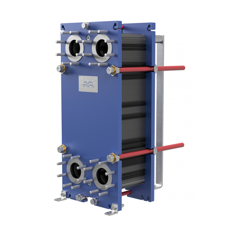
Alfalaval ALTB-SB-35 User manual

Alfalaval

Alfalaval ALTB-SB-35 User manual

Alfalaval TJ40G User manual

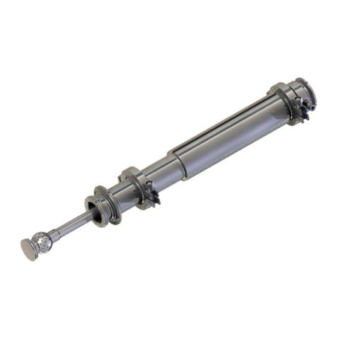
Alfalaval

Alfalaval TJ40G User manual

Alfalaval Rodem Toftejorg TZ-66 User manual

Alfalaval

Alfalaval Rodem Toftejorg TZ-66 User manual

Alfalaval AlfaNova 76 User manual

Alfalaval

Alfalaval AlfaNova 76 User manual

Alfalaval MMPX 303SGP-11 User manual

Alfalaval

Alfalaval MMPX 303SGP-11 User manual

Alfalaval AC User manual

Alfalaval

Alfalaval AC User manual

Alfalaval Pharma-X User manual

Alfalaval

Alfalaval Pharma-X User manual

Alfalaval Toftejorg MultiJet 25 User manual

Alfalaval

Alfalaval Toftejorg MultiJet 25 User manual

Alfalaval TE75P231 User manual

Alfalaval

Alfalaval TE75P231 User manual

Alfalaval Toftejorg SaniJet 20 User manual

Alfalaval

Alfalaval Toftejorg SaniJet 20 User manual

Alfalaval MBPX810H User manual

Alfalaval

Alfalaval MBPX810H User manual

Alfalaval Pharma-line S 1 User manual

Alfalaval

Alfalaval Pharma-line S 1 User manual

Alfalaval M15 User manual

Alfalaval

Alfalaval M15 User manual

Alfalaval AQ Series User manual

Alfalaval

Alfalaval AQ Series User manual

Alfalaval BaseLine M User manual

Alfalaval

Alfalaval BaseLine M User manual

Alfalaval T6 User manual

Alfalaval

Alfalaval T6 User manual

Alfalaval RV-P User manual

Alfalaval

Alfalaval RV-P User manual

Alfalaval M15 User manual

Alfalaval

Alfalaval M15 User manual

Alfalaval Toftejorg MultiJet 50 User manual

Alfalaval

Alfalaval Toftejorg MultiJet 50 User manual

Alfalaval Mini City F2 User manual

Alfalaval

Alfalaval Mini City F2 User manual

Alfalaval HLSD-2 User manual

Alfalaval

Alfalaval HLSD-2 User manual

Alfalaval Toftejorg TZ-67 User manual

Alfalaval

Alfalaval Toftejorg TZ-67 User manual

Alfalaval Contherm 6X3 User manual

Alfalaval

Alfalaval Contherm 6X3 User manual

Alfalaval GJ PF-FT User manual

Alfalaval

Alfalaval GJ PF-FT User manual

Popular Industrial Equipment manuals by other brands

schmersal AZM400Z-ST2-I1-2P2P-E manual

schmersal

schmersal AZM400Z-ST2-I1-2P2P-E manual

Bedrock UPS.500 quick start guide

Bedrock

Bedrock UPS.500 quick start guide

ixtur MAP-6 Product instructions

ixtur

ixtur MAP-6 Product instructions

Fairport PP193 OPERATOR'S, SPARE PARTS & SERVICE MANUAL

Fairport

Fairport PP193 OPERATOR'S, SPARE PARTS & SERVICE MANUAL

NCR 7350-K140 Kit instructions

NCR

NCR 7350-K140 Kit instructions

Alpha Technologies ALPHA OUTBACK ENERGY Cordex 48-1kW Installation & operation manual

Alpha Technologies

Alpha Technologies ALPHA OUTBACK ENERGY Cordex 48-1kW Installation & operation manual

Zionair SB11A Assembly and user instructions

Zionair

Zionair SB11A Assembly and user instructions

Ravaglioli G7645 Series instruction manual

Ravaglioli

Ravaglioli G7645 Series instruction manual

Circutor SVGm IP54 instruction manual

Circutor

Circutor SVGm IP54 instruction manual

CEMB MATIC 750 Operation instructions

CEMB

CEMB MATIC 750 Operation instructions

Adtech SCT 302 instruction manual

Adtech

Adtech SCT 302 instruction manual

LNS Hydrobar Express 332 Troubleshooting and Spare Parts Manual

LNS

LNS Hydrobar Express 332 Troubleshooting and Spare Parts Manual

RUD VLBG Additonal operating & safety instructions

RUD

RUD VLBG Additonal operating & safety instructions

ShopBot Desktop Series quick start guide

ShopBot

ShopBot Desktop Series quick start guide

ABB A135-H56 Operation manual

ABB

ABB A135-H56 Operation manual

ABB HT610703 Operation manual

ABB

ABB HT610703 Operation manual

Gray KwikLift KL-20 owner's manual

Gray

Gray KwikLift KL-20 owner's manual

Extrel MAX300-RTG Installation/Hardware Manual

Extrel

Extrel MAX300-RTG Installation/Hardware Manual

manuals.online logo
manuals.online logoBrands
  • About & Mission
  • Contact us
  • Privacy Policy
  • Terms and Conditions

Copyright 2025 Manuals.Online. All Rights Reserved.