3
VLBG
• RUD supplies the Vario length complete with a
washer and crack-detected nut corresponding to
DIN EN ISO 7042 (DIN 980) or will be supplied
with a crack inspected collar nut acc. to DIN 6331.
• If the VLBG is used exclusively for lashing, the
value of the working load limit can be doubled.
LC = permissible lashing capacity = 2 x WLL
HINT
If the VLBG is or was used as a lashing
point, it must not be used for lifting later on!
3.2 Hints for the assembly
Basically essential:
• The material construction to which the lifting point
will be attached should be of adequate strength to
withstand forces during lifting without deformation.
The German testing authority BG, recommends
the following minimum for bolt lengths:
1 x M in steel (minimum quality S235JR
[1.0037])
1,25 x M in cast iron (for example GG 25)
2 x M in aluminium alloys
2,5 x M in aluminium-magnesium alloys
(M = diameter of RUD lifting point bolt, for ex. M 20)
• When lifting light metals, nonferrous heavy metals
and gray cast iron the thread has to be chosen in
such a way that the working load limit of the thread
corresponds to the requirements of the respective
base material.
• The lifting points must be positioned on the load
in such a way that movement is avoided during
lifting:
• For single leg lifts, the load ring should be
positioned vertically above the centre of
gravity of the load.
• For two leg lifts, the lifting points must be
equidistant to/or above the centre of gravity
of the load.
• For three and four leg lifts, the lifting
points should be arranged symmetrically
around the centre of gravity in the same
plane, if possible.
• Load symmetry:
The working load limit of individual RUD lifting
points are calculated using the following formula
and are based on symmetrical loading:
WLL = working load limit
G = load weight (kg)
n = number of load bearing legs
ß = angle of inclination of the chain to the vertical
WLL=G
n x cos ß
The calculation of load bearing legs is as follows:
symmetrical asymmetrical
two leg 2 1
three / four leg 3 1
table 1: Load bearing strands (see table 2)
HINT
With unsymmetrical loads, the WLL of each
Lifting Point must be at least as high as the
weight of the load.
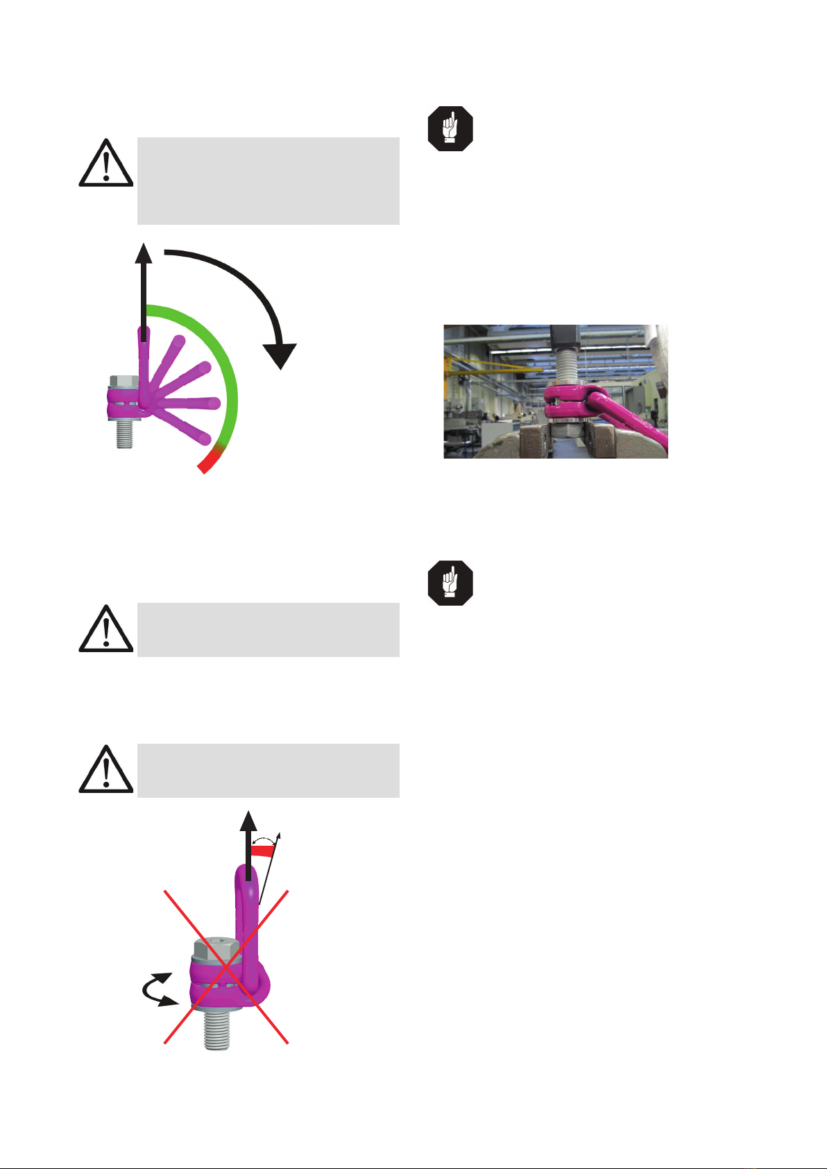
• A plane bolt-on surface (ØD, table 3) with a perpen-
dicular thread hole must be guaranteed. The thread
must be carried out acc. to DIN 76 (countersink
max. 1.05xd)
• Tapped holes must be machined deep enough so
that the bearing surface of the lifting point will be
supported. Machine through holes up to DIN EN
20273-middle.
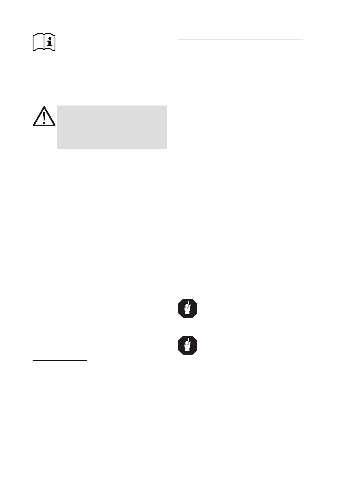
• The VLBG must be rotatable 360° when installed.
Please observe the following:
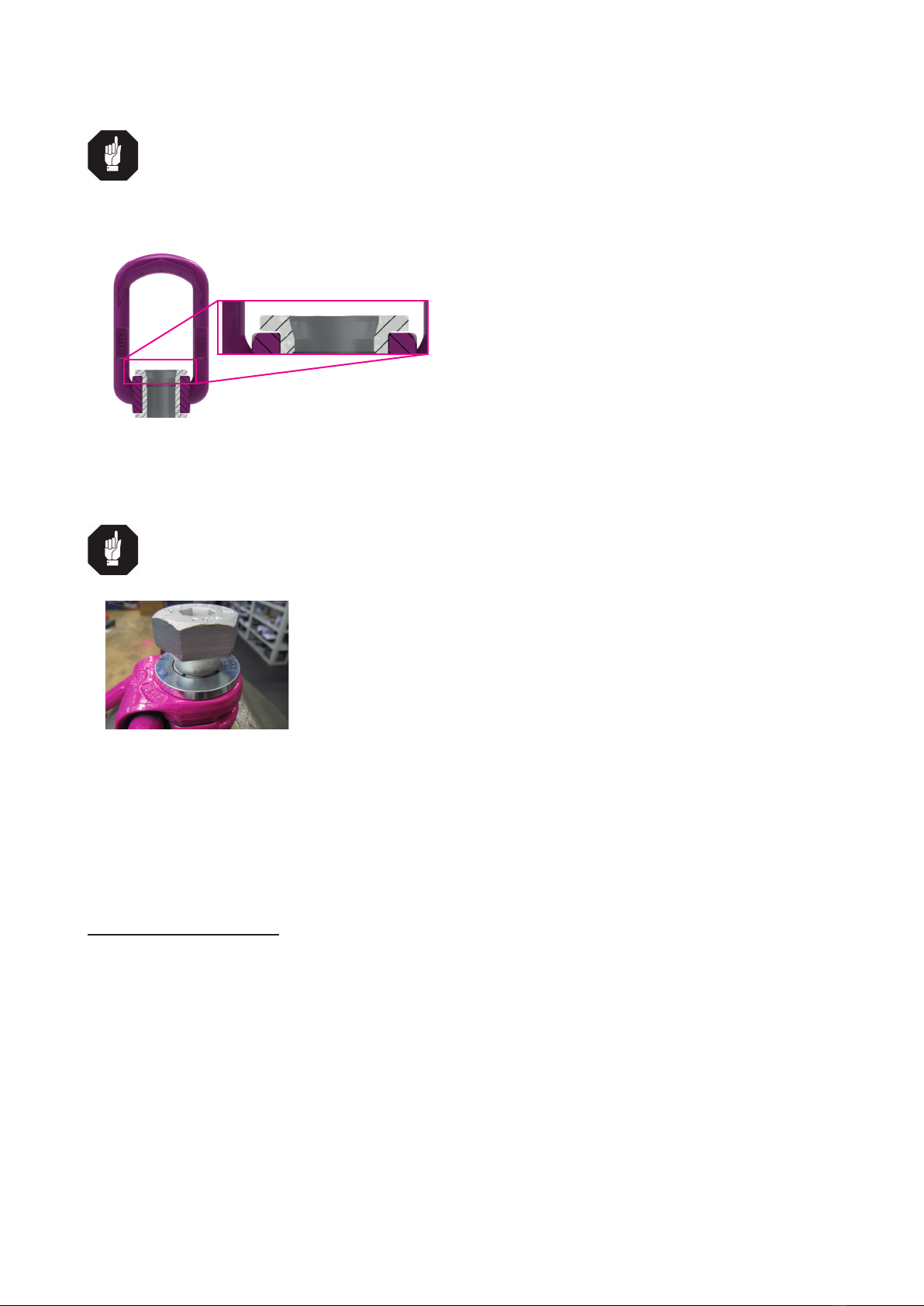
• For a single use hand tightening with a span-
ner is sufciant. Bolt supporting area must sit
proper on bolt-on surface.
• For long term application the VLBG must
be tightened with torque according to table 3
(+/- 10 %).
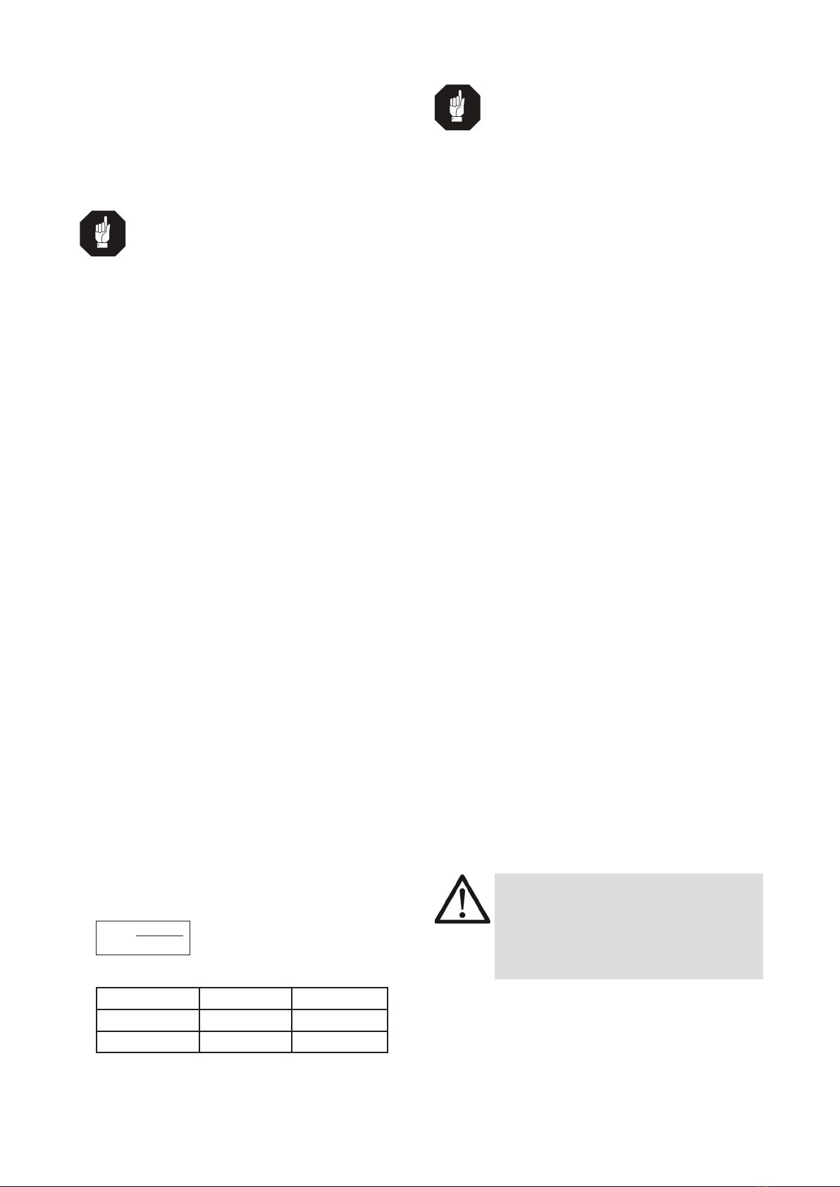
• When turning loads using the VLBG (see
chapter 3.3.2 permissible lifting- and turning
process) it is necessary to tighten the bolt with
a torque (+/- 10 %) acc. to chart 3.
• With shock loading or vibrations, especially at
through hole fixtures with a nut at the end of
the bolt, accidential release can occure.
Securing possibilities: Observe torque moment,
use liquid securing glue f.e. Loctite (can be adap-
ted to the usage, observe manufacturer hints) or
assemble a form closure bolt locking device f.e. a
castle nut with cotter pin, locknut etc.
• Finally check the proper assembly (see chapter 4
Inspection / repair).
3.3 User instructions
3.3.1 General information for the usage
• Always regularly observe the appearance of the
whole lifting point (e.g. xed lifting point/slings)
before using it (secured bolt seat, strong corrosion,
cracks on load-bearing parts, deformations). Refer
to chapter 4 Inspection / repair.
ATTENTION
Wrong assembled or damaged VLBG as
well as improper use can lead to injuries
of persons and damage of objects when
load drops.
Please inspect all VLBG before each use.