Bedrock UPS.500 User manual

UPS.500
Quick Start Guide

Important User Information
The UPS.500 contains lithium-ion batteries. The
product is not field-serviceable. Contact Bedrock
Automation for instructions on returning the
UPS.500.
Never attempt to open the UPS.500 enclosure. The
enclosure is securely sealed. Opening the enclosure
will void the warranty and cause the UPS.500 to be
inoperable.
The UPS.500 contains lithium-ion batteries. The
output port may carry voltage even when the
UPS.500 is not connected to a power source.
Always use an appropriate fuse on the power in
and power out connections.
For both the panel and pipe mount configurations,
it is required that the UPS.500 mounting bracket is
grounded.

1 - Status LEDs
Ethernet Activity
Ethernet Link
Tri-color UPS Status

2 - Ports
Note: Bedrock part no. CI00100 or Phoenix
Contact part no. 1656990 must be
used for the Ethernet connector in
order to maintain the IP66/IP67 rating.
Note: A shielded
Ethernet cable is
required.
Power
Out
Power
In Relay
Enable
Ethernet

3 –UPS.500 Block Diagram
Note: Battery Enable Connector must be connected prior to power up
Workstation
Running
OPC UA
or
Bedrock
SIO4.E
comm.
module
Load
Power
Supply
Recommended
Fusing
Power
Out
Power
In
Recommended
Fusing
To Discrete
Inputs for
Alarming Relay
Output
(optional)
Ethernet
SPS.500 or Equivalent
24 V Power Supply
Battery
Enable
Connector

4 –Parts List (Panel Mount)
1
2
3
ITEM
NO.
DESCRIPTION
QTY.
1
UPS.500 ASSEMBLY
1
2
#14 x 1” SELF TAPPING
SCREW
4
3
UPS MOUNTING BRACKET
1
Use Bedrock Part No. MI00128 when ordering the
UPS Mounting Bracket Assembly (Panel Mount)

5 –Parts List (Pipe Mount)
1
2
4
Use Bedrock Part No. MI00127 when ordering the
UPS Mounting Bracket Assembly (Pipe Mount)
ITEM
NO.
DESCRIPTION
QTY.
1
UPS.500 ASSEMBLY
1
2
3/8”-16 x 3/4 HEX BOLT
4
3
UPS MOUNTING BRACKET
1
4
2” SCHEDULE 40 PIPE
MOUNTING BRACKET
1
5
3/8”- WASHER
4
6
3/8”-16 HEX NUT
4
3
5
6

6 –Mount UPS
2
1
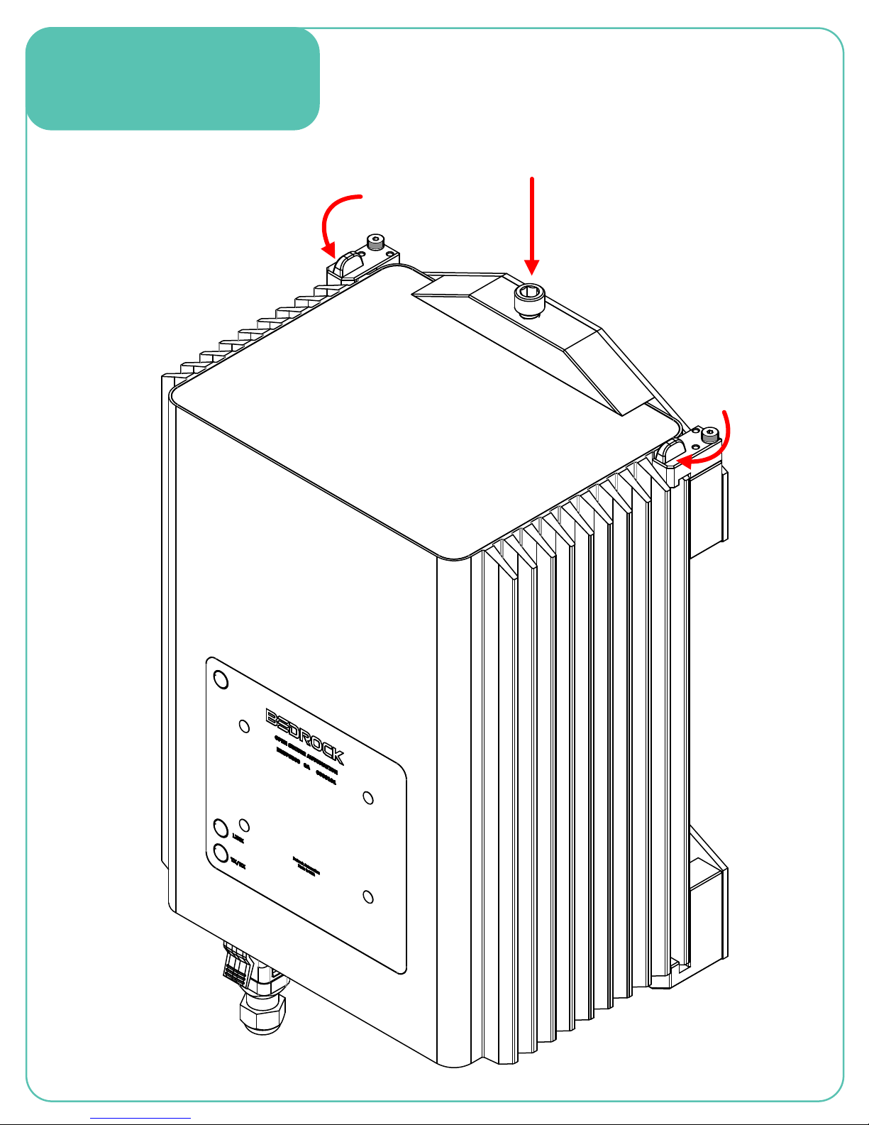
7 –Clamp UPS
4
3
3

CAUTION: See panel 12 for relay
contact rating specification.
8 –UPS Cables
Note: See panel 9 for pin out tables.
Connect drain wire to panel ground.
Power In
Power Out
Relay
PIN 1
PIN 2
PIN 3
PIN 4
PIN 5
PIN 6
DRAIN WIRE
PIN 1
PIN 2
PIN 3
PIN 4
PIN 5
PIN 6
DRAIN WIRE
DRAIN WIRE
PIN 6 RELAY B (NO)
PIN 5 RELAY B (COM)
PIN 4 RELAY B (NC)
PIN 3 RELAY A (NO)
PIN 2 RELAY A (COM)
PIN 1 RELAY A (NC)
Bedrock Part No. UPSPOWRIN
Bedrock Part No. UPSPOWOUT
Bedrock Part No. UPSRLYCBL

9 –Cable Pin Outs
Power In
Power Out
Relay
Pin/Wire
Function
Color
PIN 1
RELAY A (NC)
BLACK
PIN 2
RELAY A (COM)
RED
PIN 3
RELAY A (NO)
WHITE
PIN 4
RELAY B (NC)
GREEN
PIN 5
RELAY B (COM)
ORANGE
PIN 6
RELAY B (NO)
BLUE
PIN 7
DRAIN WIRE
N/A
NOTE: Cable length should not
exceed 9 meters (29.5 ft.).
Note: Figures show the connector end of each cable.
Pin/Wire
Function
Color
DRAIN WIRE
GROUND
N/A
PIN 1
24 V DC
RED
PIN 2
24 V DC
RED
PIN 3
24 V DC
RED
PIN 4
24 V RET
BLACK
PIN 5
24 V RET
BLACK
PIN 6
24 V RET
BLACK
Pin/Wire
Function
Color
DRAIN WIRE
GROUND
N/A
PIN 1
24 V DC
RED
PIN 2
24 V DC
RED
PIN 3
24 V DC
RED
PIN 4
24 V RET
BLACK
PIN 5
24 V RET
BLACK
PIN 6
24 V RET
BLACK
NOTE: Cable length should not
exceed 9 meters (29.5 ft.).
CAUTION: Each contact is rated for 10 amps at
25°C. In order to support full capacity,
all wires must be connected to their
respective contacts.
CAUTION: Each contact is rated for 10 amps at
25°C. In order to support full capacity,
all wires must be connected to their
respective contacts.

10 –Cable Alignment
Step 1: Align open arrow with arrow on mating
connector and then press together.
Step 2: Rotate ¼ turn clockwise to the locked
position.
1
2

11 –Enable Connector
The enable connector must be
connected before the power input
cable for the UPS.500 to be operable.
Remove the enable connector prior to
transporting the UPS.500
Enable
Connector
Use Bedrock Part No. MI00097 when ordering the Enable Connector

12 - Specifications
UPS.500 Electrical Specifications
Input voltage
22-26 volts
Hold up time
See UPS.500 Hold Up Time Table
Maximum load current
12 amps
Short circuit current
20 amps (maximum)
Maximum load capacitance
8000 µF
Standby power
< 2.5 watts
Charging power
Programmable: 48 watts to 150 watts
Charging time
4 to 10 hours (dependent upon configured charging
power)
Charging current
1 to 7 amps (dependent upon configured charging
power)
Input voltage
0.3 volts
UPS.500 General Specifications
Communication/output ports:
Two Type C relay contacts rated
Max switching voltage
125 V DC, 150 V AC
Max switching current
1 amp resistive load
One 10/100 Ethernet port with
IEEE-1588 timestamp
Status indicators:
Tri-color status LED
See UPS.500 LED Status Codes Table
Yellow Ethernet link LED
On indicates Ethernet link
Yellow Ethernet activity LED
On indicates Ethernet activity
Dimensions
Height
235 mm (9.25 inches)
Depth
159 mm (6.25 inches)
Width
292 mm (11.5 inches )
Weight
11.34 kg (25 pounds)
Enclosure
IP66/IP67
NEMA Ratings: 4, 5, 6
Metal: Aluminum
Coating: Electroless nickel plated
UPS.500 Hold Up Time (reflects fully charged pack)
12 amps
45 minutes
10 amps
75 minutes
8 amps
105 minutes
6 amps
135 minutes
4 amps
165 minutes
2 amps
180 minutes

13 –Specifications and Certifications
IEC Environmental Testing
IEC 60068-2-27
Shock
IEC 60068-2-6
Vibration
UPS.500 Environmental Specifications
Operating temperature
-10°C to 60°C
Storage temperature
-20°C to 60°C
Operating humidity
5% to 100% relative humidity
FCC Testing
CFR FCC Part 15 Subpart B, Class A (2016)
Radiated Emissions
CE Testing - European EMC Directive 2014/30/EU including:
EN 61326-1
EMC Requirements
CISPR 11: 2010
Radiated Emissions
IEC 61000-4-2
ESD Immunity
IEC 61000-4-3
Radiated RF Immunity
IEC 61000-4-4
Electrical Fast Transient/Burst Immunity
IEC 61000-4-5
Surge Immunity
IEC 61000-4-6
Conducted RF Immunity
EMP Testing
MIL-STD-461-E
Requirement RS105
Radiated Susceptibility
Transient Electromagnetic Field
UPS.500 LED Status Codes
System State
Color
Number of Blinks and Duration
Normal, battery pack ready
Green
Steady
Normal, battery pack charging
Orange
1 blink –repeats while condition persists
Normal, battery pack 85% charged
Green
1 blink –repeats while condition persists
Main power failure
Blue
1 blink –repeats while condition persists
Main power failure, battery pack depleted
Red
1 blink –repeats while condition persists
Main power recovery
Blue
4 blinks –repeats while condition persists
Fault
Purple
4 blinks –repeats while condition persists
Safety Certifications
UL 508
Industrial Control Equipment
Class I Division 2
Hazardous Locations
CE mark

Corporate Headquarters
San Jose, California
East Coast Office
Boston, Massachusetts
Phone: +1 (781) 821-0280
Support available from 8 am to 8 pm Eastern Time
Fax: +1 (781) 821-0288
Email: support@bedrockautomation.com
Website
www.bedrockautomation.com
SUPPORT
Bedrock Automation UPS.500 Quick Start BRDOC105_002
Other manuals for UPS.500
3
Table of contents
Other Bedrock Industrial Equipment manuals


