2 Safety
All warnings in the manual are summarised on this page.
Pay special attention to the instructions below so that severe personal injury and/or damage to the Agitator are avoided.
2.4 Safety precautions
Installation:
Always read the technical data thoroughly (see chapter 6.1 Technical data).
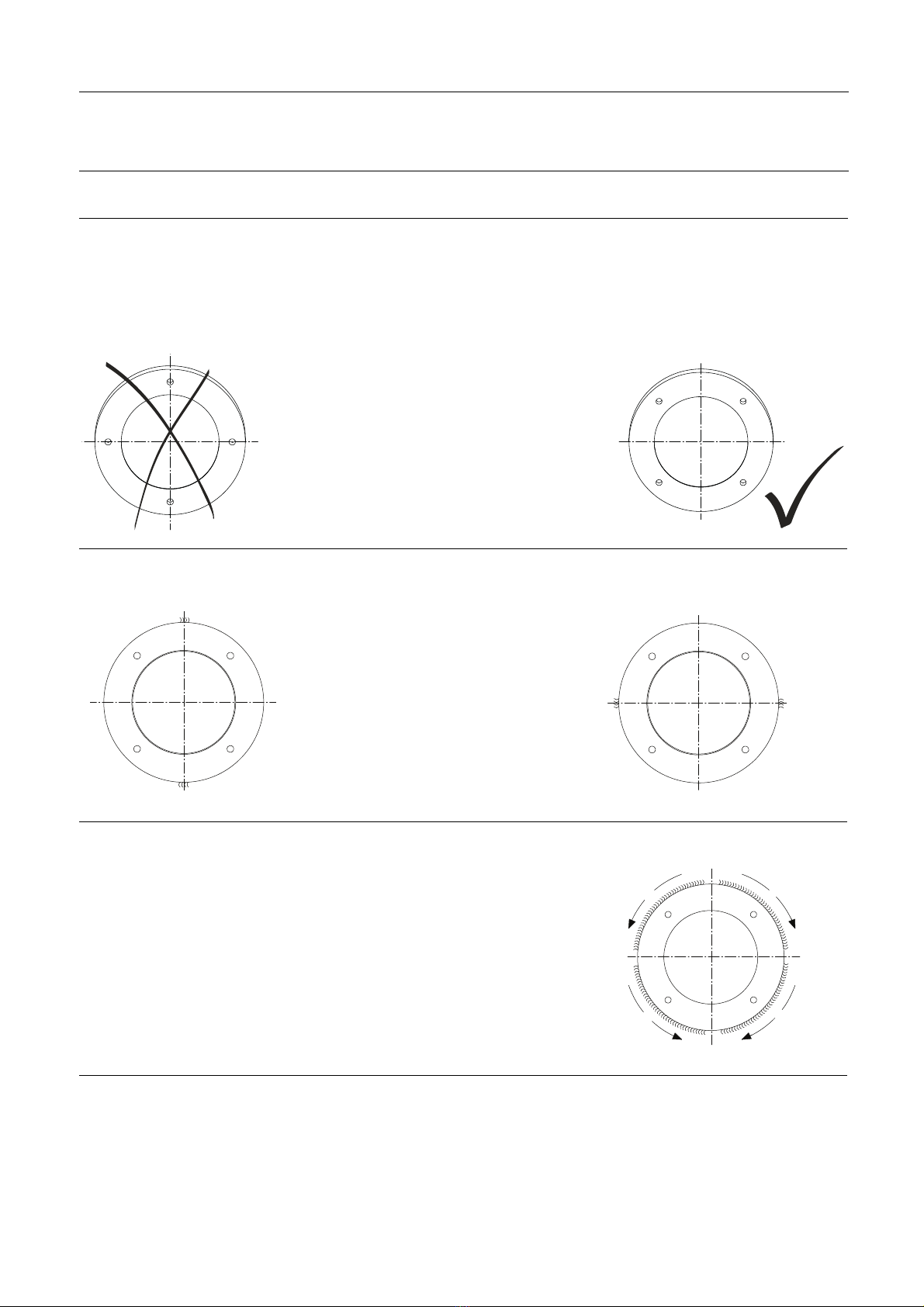
Always follow installation instructions thoroughly (see chapter 3 Installation).
Never expose the Agitator to undue vibrations or shocks.
Never start Agitator in the wrong rotation direction.
Always follow drive unit installation instruction thoroughly (see chapter 8 Appendix).
Ensure that the tank media is not corrosive to the Agitator.
Only install the Agitator in environments within temperature limit: -20°C and +40°C.
Only install the Agitator in altitudes less than 1000 m above sea level.
Always ensure that the Agitator has sufficient cooling around the lantern, may not be wrapped with isolating materials.
!
Ensure that installation is in accordance with EN 60079-14.
Beware of ignition temperature can be decreased when enclosed by the equipment/tank (see EN 14522).
Never touch the moving parts while the Agitator is connected to the power supply.
Operation:
Always read the technical data thoroughly (see chapter 6.1 Technical data).
Always read supplier instructions thoroughly (see chapter 8 Appendix).
Always make sure that the Agitator corresponds to the category marked on the name plate:
Gas atmosphere:
Never start Agitator in the wrong rotation direction.
Never use the Agitator for hybrid mixture.
Always rinse well with clean water after cleaning.
Beware of temperature limitations.
Beware of Agitator in operation can produce sound levels in excess of 85dB(A).
Never operate continuously within 20% of critical oscillation speed (see chapter 6.1 Technical data).
!
Beware of static electricity risk when the media conductivity is below 1000pS/m. (Recommendations: CLC/TR
50404 or IEC/TS60079-32).
Never touch the moving parts while the Agitator is connected to the power supply.
Maintenance:
Always read the technical data thoroughly (see chapter 6.1 Technical data
Always follow the maintenance instruction thoroughly (see chapter 5 Maintenance).
Always follow the maintenance instruction from drive unit supplier (see chapter 8 Appendix).
Always study the parts list and assembly drawing carefully (see chapter 7 Parts list and drawing & service kits).
Never replace ATEX Agitator with other type of Alfa Laval Agitator.
Ensure that maintenance is in accordance with relevant standards EN 60079-17 and EN 60079-19.
!
Never touch the moving parts while the Agitator is connected to the power supply.
Always disconnect the power supply while servicing the Agitator.
Transportation:
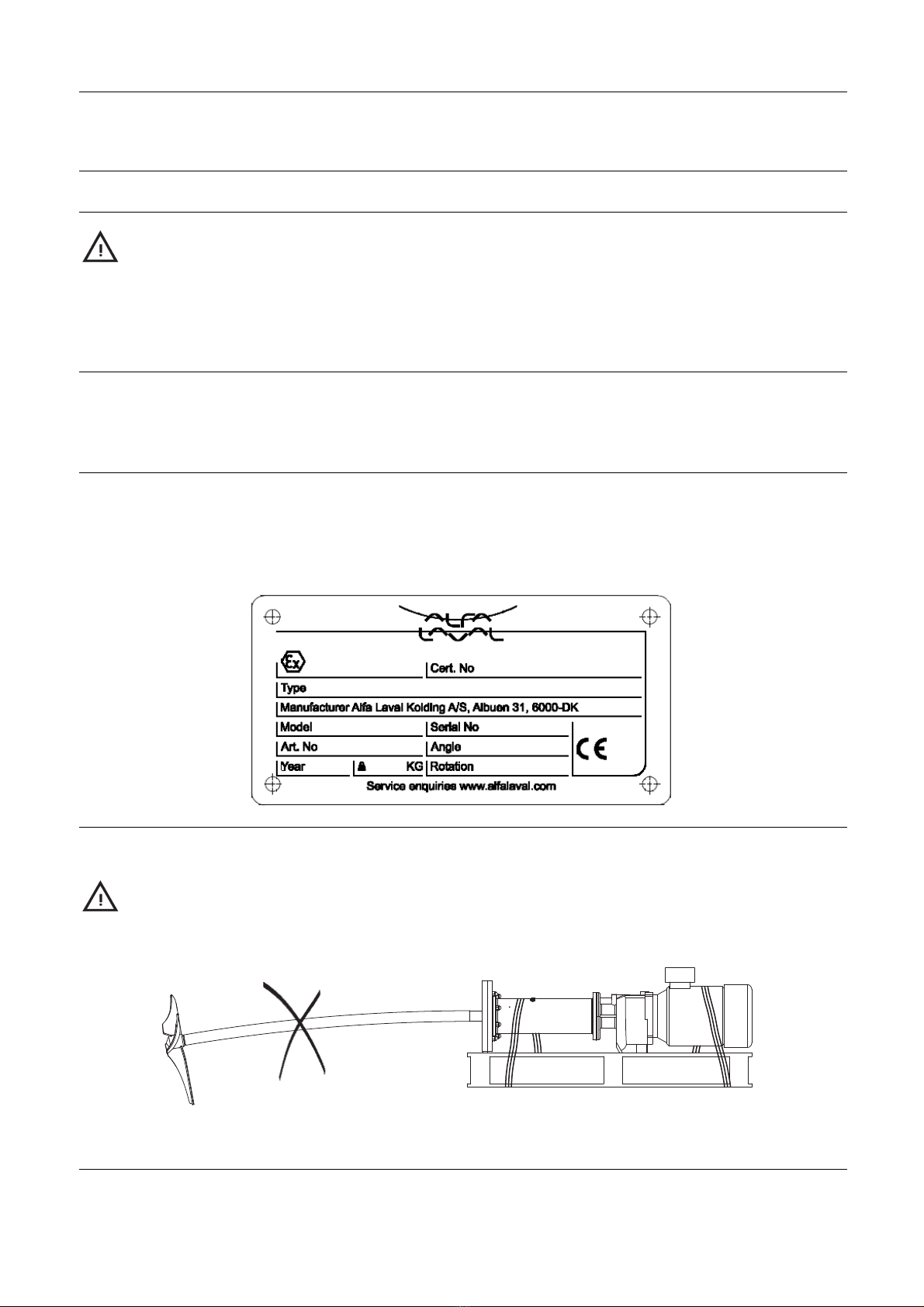
Always transport the Agitator in original packaging.
Always support the shaft adequately, to protect shaft and bearings.
Never expose the Agitator to undue vibrations or shocks.
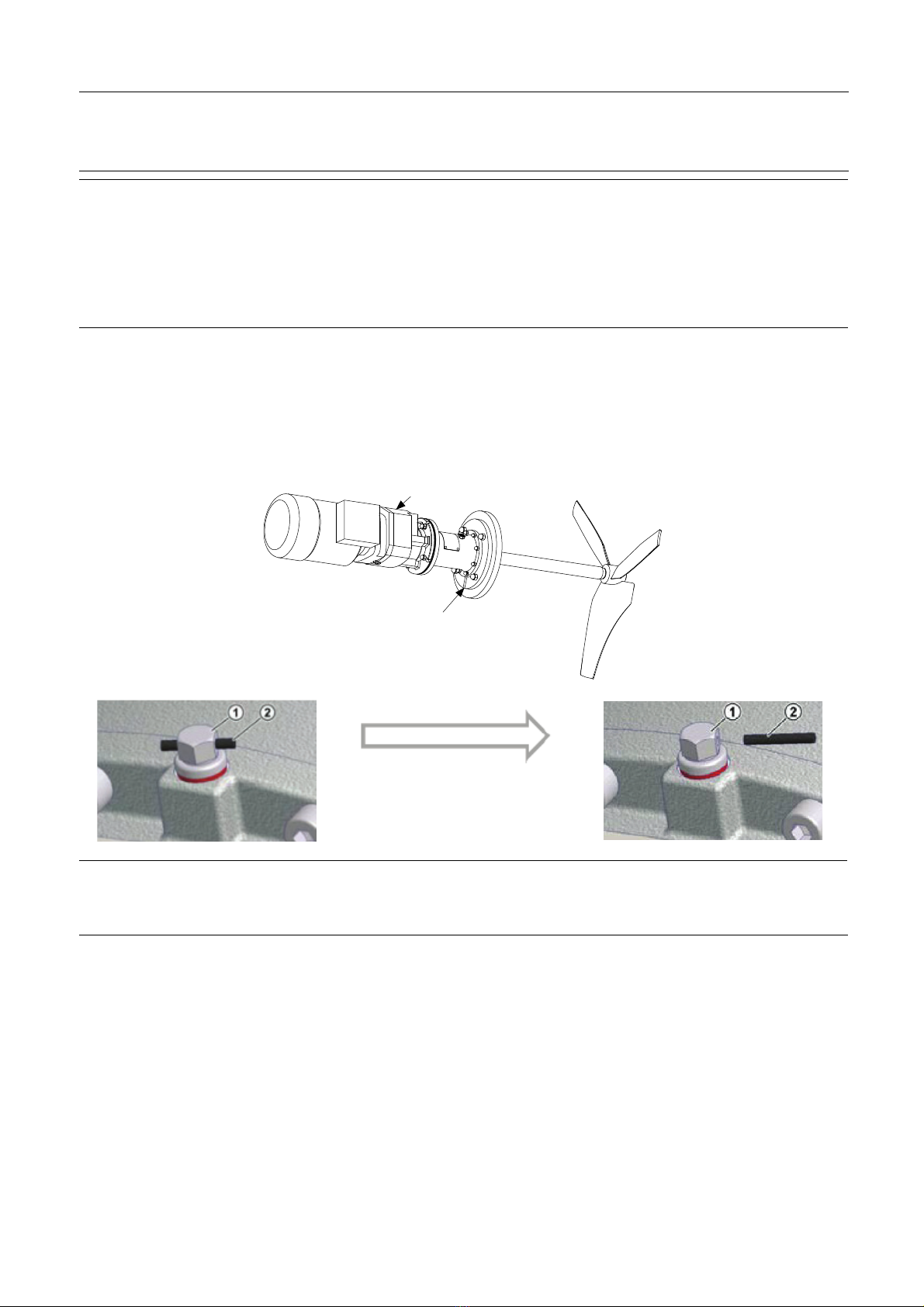
Control for oil leakage on gears with vent screw.
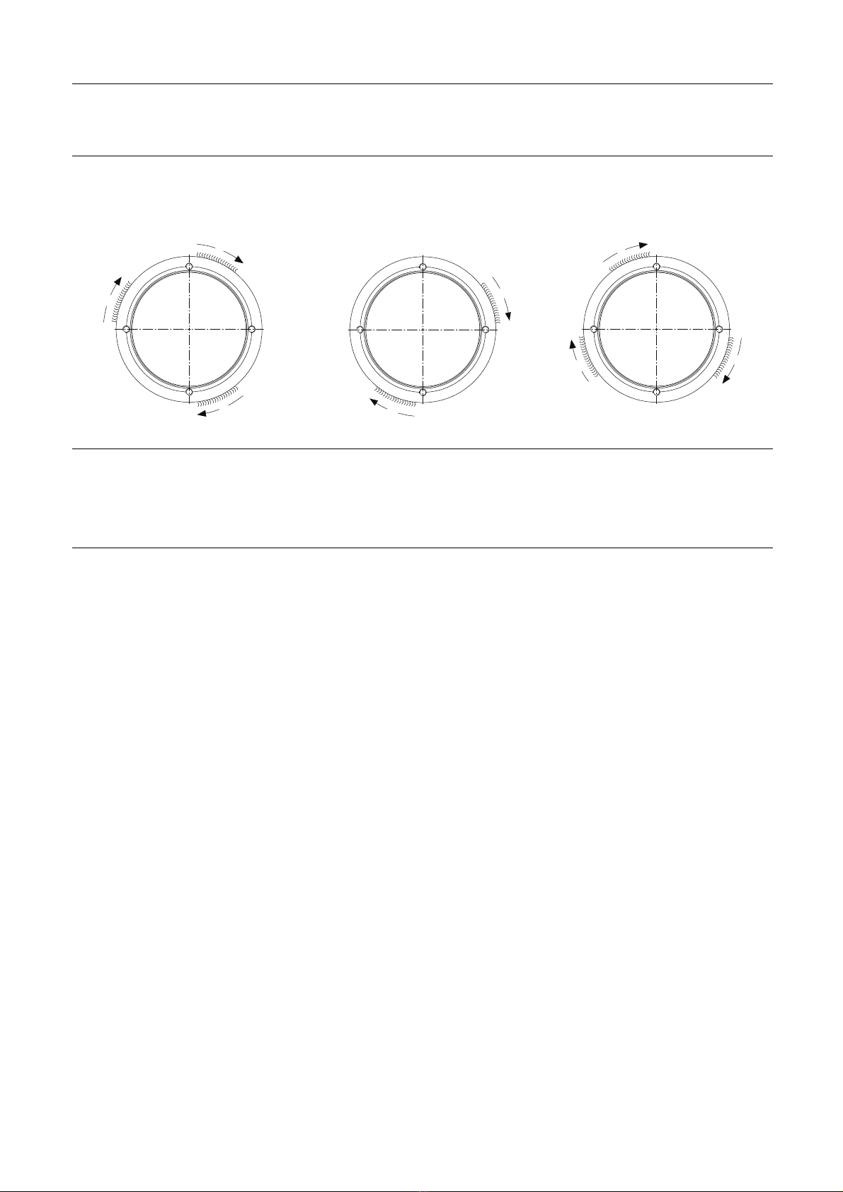
Ensure correct rotation direction of impeller before startup and after any maintains there might have impact on the direction.
6