Alfalaval ALT series User manual

4303-0021
ESE03504-EN2 2017-03
Original manual
Instruction Manual
Alfa Laval Agitator - ALT / ALTB


Table of contents
The information herein is correct at the time of issue but may be subject to change without prior notice
1. EC Declaration of Conformity ....................................................................... 5
2. Safety .................................................................................................... 6
2.1. Important information ............................................................................. 6
2.2. Warning signs ..................................................................................... 6
2.3. Intended use ...................................................................................... 6
2.4. Safety precautions ................................................................................ 7
3. Installation .............................................................................................. 8
3.1. Unpacking/delivery ............................................................................... 8
3.2. Installation ......................................................................................... 11
3.3. Pre-use check ..................................................................................... 22
4. Operation ............................................................................................... 25
4.1. Operation/Control ................................................................................. 25
4.2. Troubleshooting ................................................................................... 26
4.3. Cleaning - recommendations .................................................................... 27
5. Maintenance ........................................................................................... 28
5.1. General Maintenance ............................................................................. 29
5.2. Replacement of drive unit (with bearing frame) ................................................ 30
5.3. Replacement of drive unit (without bearing frame) ............................................ 32
5.4. Replacement of drive unit (Motor and shaft unit) .............................................. 34
5.5. Dismantling and mounting shaft (only for bearing frame) ..................................... 35
5.6. Replacement of bearings, type B20, B25, B25/30, B35, B35/40, B45, B45/50, B55,
B55/60 ............................................................................................. 37
5.7. Replacement of bearings, type BC160DH ..................................................... 39
5.8. Replacement of bearing, type BC160D ........................................................ 41
5.9. Replacement of bearings type BC160 .......................................................... 43
5.10.Replacement of shaft seal, type D .............................................................. 45
5.11.Replacement of shaft seal, type DC ............................................................ 48
5.12.Replacement of shaft seal, type S .............................................................. 51
5.13.Replacement of shaft seal, type S3 ............................................................. 54
5.14.Replacement of shaft seal, type R or G ........................................................ 56
5.15.Replacement of shaft seal, type V .............................................................. 59
5.16.Replacement of wear bushing ................................................................... 61
6. Technical Data ......................................................................................... 62
6.1. Technical data ..................................................................................... 62
6.2. Storage ............................................................................................ 69
7. Part lists, part drawings and service kits ......................................................... 70
7.1. Agitator Main Components, Drive end .......................................................... 70
7.2. Agitator Main Components, Wet end ........................................................... 72
7.3. Bearing frame, B20, B25, B25/30, B35, B35/40, B45, B45/50, B55, B55/60 ............. 74
7.5. Bearing frame BC160/35, BC160D/30, BC160DH/30 ....................................... 78
7.6. Shaft seal, type S ................................................................................. 80
7.7. Shaft seal, type S3 ................................................................................ 82
7.8. Shaft seal, type D ................................................................................. 84
7.9. Shaft seal, type DC ............................................................................... 86
7.10.Shaft seal, type R ................................................................................. 88
7.12.Shaft seal, type G ................................................................................. 92
3

Table of contents
The information herein is correct at the time of issue but may be subject to change without prior notice
7.14.Shaft seal, type V ................................................................................. 96
7.15.Intermediate steady bearing support ........................................................... 98
7.16.Bottom steady bearing support, type 1 ........................................................ 100
7.18.Bottom steady bearing support, type 2 ........................................................ 104
8. Appendix ............................................................................................... 106
8.1. Drive unit instructions ............................................................................. 106
4

1 EC Declaration of Conformity
The Designated Company
Alfa Laval Kolding A/S
Company Name
Albuen 31, DK-6000 Kolding, Denmark
Address
+4579322200
Phone No.
hereby declare that
Agitator - EnSaFoil / EnSaFerm 10.000 - 100.000
Designation Serial no(s)
GX = GC, GR or GP
ALT(B)-ME-(GX)-BC160D(H)/30(L)F-SX-SH-(n)(PXXXXDYY)(-PXXXXDYLY)(-LXXXXY)(-MSXX)(-BSXX) BXX/XX = B20, B25, B25/30, B35, B35/40,
ALT(B)-ME-(GX)-BC160/35(L)F-SX-SH-(n)(PXXXXDYY)(-PXXXXDYLY)(-LXXXXY)(-MSXX)(-BSXX) B45, B45/50, B55, B55/60
ALT(B)-ME-(GX)-BXX/XX(L)F-SX-SH-(n)(PXXXXDYY)(-PXXXXDYLY)(-LXXXXY)(-MSXX)(-BSXX) SX = S, S3
ALT(B)-ME-(GX)-BC160D(H)/30(L)F-D(C)-SH-(n)(PXXXXDYY)(-PXXXXDYLY)(-LXXXXY)(-MSXX)(-BSXX) SH = S500-S15000
ALT(B)-ME-(GX)-BC160/35(L)F-D(C)-SH-(n)(PXXXXDYY)(-PXXXXDYLY)(-LXXXXY)(-MSXX)(-BSXX) PXXXX P125, P150, P175, P200, P225,
ALT(B)-ME-(GX)-BXX/XX(L)F-D(C)-SH-(n)(PXXXXDYY)(-PXXXXDYLY)(-LXXXXY)(-MSXX)(-BSXX) P250, P300, P350, P400
ALT(B)-ME-(GX)-BC160D(H)/30(L)F-R-SH-(n)(PXXXXDYY)(-PXXXXDYLY)(-LXXXXY)(-MSXX)(-BSXX) P450, P500, P550, P600, P650,
ALT(B)-ME-(GX)-BC160/35(L)F-R-SH-(n)(PXXXXDYY)(-PXXXXDYLY)(-LXXXXY)(-MSXX)(-BSXX) P700, P750, P800, P900, P1000,
ALT(B)-ME-(GX)-BXX/XX(L)F-R-SH-(n)(PXXXXDYY)(-PXXXXDYLY)(-LXXXXY)(-MSXX)(-BSXX) P1100, P1300, P1500, P1700, P1900
ALT(B)-ME-(GX)-BC160D(H)/30(L)F-G-SH-(n)(PXXXXDYY)(-PXXXXDYLY)(-LXXXXY)(-MSXX)(-BSXX) LXXXX = L600, L800, L900, L1100, L1300,
ALT(B)-ME-(GX)-BC160/35(L)F-G-SH-(n)(PXXXXDYY)(-PXXXXDYLY)(-LXXXXY)(-MSXX)(-BSXX) L1500, L1700
ALT(B)-ME-(GX)-BXX/XX(L)F-G-SH-(n)(PXXXXDYY)(-PXXXXDYLY)(-LXXXXY)(-MSXX)(-BSXX) DY = D2, D3
ALT(B)-ME-(GX)-ZZ(L)F-SX-SH-(n)(PXXXXDYY)(-PXXXXDYLY)(-LXXXXY)(-MSXX)(-BSXX) Y = P, G
ALT(B)-ME-(GX)-ZZ(L)F-D(C)-SH-(n)(PXXXXDYY)(-PXXXXDYLY)(-LXXXXY)(-MSXX)(-BSXX) BSXX BS1P, BS1G, BS2P, BS2G
ALT(B)-ME-(GX)-ZZ(L)F-R-SH-(n)(PXXXXDYY)(-PXXXXDYLY)(-LXXXXY)(-MSXX)(-BSXX) MSXX = MS2P, MS2G
ALT(B)-ME-(GX)-ZZ(L)F-G-SH-(n)(PXXXXDYY)(-PXXXXDYLY)(-LXXXXY)(-MSXX)(-BSXX) ZZ = 20, 25, 30, 35, 40, 45, 50, 55, 60, 65,
ALT-ME-ZZF-V-SH-PXXXXDYY 70, 75, 80, 90
Type Type variation
is in conformity with the following directives:
Machinery Directive 2006/42/EC++
Regulation (EC) 1935/2004
The person authorised to compile the technical file is the signer of this document.
Global Product Quality Manager
Pumps, Valves, Fittings and Tank Equipment Lars Kruse Andersen
Title Name
Kolding 2016-10-01
Place Date Signature
5

2 Safety
Unsafe practices and other important information are emphasised in this manual.
Warnings are emphasised by means of special signs.
Always read the manual before using the Agitator!
Illustrations are only to illustrate the problem and is NOT a drawing of the current Agitator!
2.1 Important information
WARNING
Indicates that special procedures must be followed to avoid serious personal injury.
CAUTION
Indicates that special procedures must be followed to avoid damage to the agitator!
NOTE
Indicates important information to simplify or clarify procedures.
2.2 Warning signs
General warning:
Dangerous electrical voltage:
2.3 Intended use
- The Alfa Laval Agitator is only for mixing/stirring of liquids in a tank.
- The Agitator is only for mounting positions as specified on the nameplate by the first group of letters of the type designation.
ALT(B)- is for top mounting, ALS- is for side mounting and ALB- is for bottom mounting.
The exact mounting angle is specified on the Name Plate and must be followed.
- The different duties and operation data like pressure, speed and media temperature, which the Agitator is designed for, can
be found in the Alfa Laval quotation agreement and may not be exceeded by all means.
1) The Alfa Laval quotation agreement has been exchanged during the quote process between a technical purchaser and Alfa Laval. If you are
not in hold of the Alfa Laval quotation agreement, please get through to your local Alfa Laval contact, inform the Agitator serial number and
article number which is stated on the Name Plate and you will obtain the Alfa Laval quotation agreement.
6

2 Safety
All warnings in the manual are summarised on this page.
Pay special attention to the instructions below so that severe personal injury and/or damage to the Agitator are avoided.
2.4 Safety precautions
Installation:
Always read the technical data thoroughly. (See chapter 6 Technical Data) !
Always follow installation instructions thoroughly. (See chapter 3 Installation)
Never expose the Agitator to undue vibrations or shocks.
Never start Agitator in the wrong rotation direction
Ensure that the tank media is not corrosive to the Agitator.
Only install the Agitator in environments within temperature limit: -20°C and +40°C.
Only install the Agitator in altitudes less than 1000 m above sea level.
Never touch the moving parts while the Agitator is connected to the power supply.
Operation:
Always read the technical data thoroughly. (See chapter 6 Technical Data) !
Always read supplier instructions thoroughly. (See chapter 8 Appendix).
Never start Agitator in the wrong rotation direction.
Always rinse well with clean water after cleaning.
Beware of temperature limitations.
Beware of Agitator in operation can produce sound levels in excess of 85dB(A).
Never operate continuously within 20% of critical oscillation speed (see chapter 6 Technical Data).
Never touch the moving parts while the Agitator is connected to the power supply.
Maintenance:
Always read the technical data thoroughly. (See chapter 6 Technical Data) !
Always follow the maintenance instruction thoroughly. (See chapter 5 Maintenance)
Always follow the maintenance instruction from drive unit supplier (see chapter 8 Appendix)
Always study the parts list and assembly drawing carefully. (See chapter 7 Part lists, part drawings and service kits)
Never touch the moving parts while the Agitator is connected to the power supply.
Always disconnect the power supply while servicing the Agitator.
Ensure correct rotation direction of impeller before startup and after any maintains there might have impact on the
direction.
7
3 Installation
The instructions manual is part of the delivery.
Study the instructions carefully
3.1 Unpacking/delivery
Always use lifting equipment when handling the Agitator (see step 3).
CAUTION!
Alfa Laval cannot be held responsible for incorrect unpacking.
Step 1
Inspect the delivery for visible transportation damages - all issues to be reported to carrier
Step 2
Check the delivery for:
1. Complete Agitator
2. Nameplate designations
3. Delivery note
4. Seperate instruction manuals from suppliers 8 Appendix
4303-0006
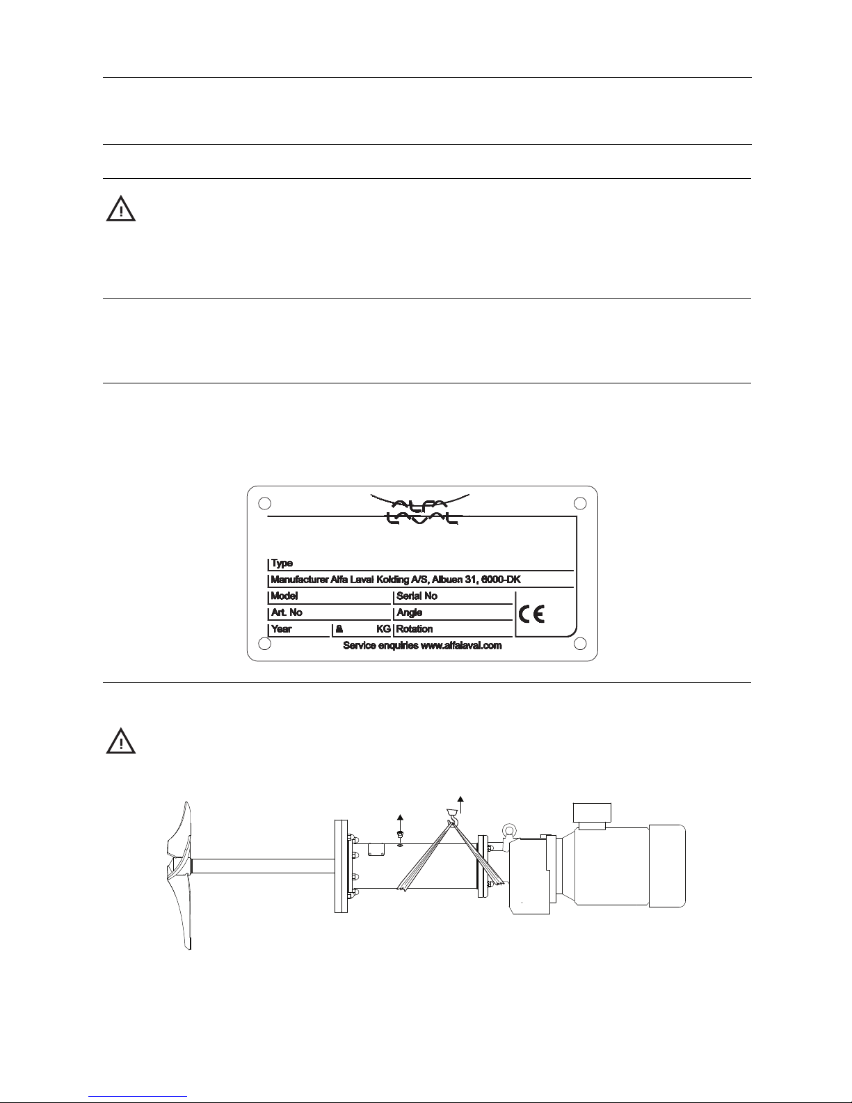
Step 3
Lifting instructions:
Always use the correct lifting equipment (see Agitator weight on name plate).
Locate Centre of gravity before moving the Agitator.
TD605-100
1
2
8

3 Installation
The instructions manual is part of the delivery.
Study the instructions carefully
TD605-103
WARNING!
Do NOT use eye bolts on gear motor to lift the Agitator. They are only fir gear motor removal.
TD605-101
WARNING!
Do NOT use eye bolts on shroud (if any) to lift the Agitator. They are only for shroud removal.
TD605-172
CAUTION!
Alfa Laval highly recommends NOT to use shaft as lifting point.
TD605-104
9

3 Installation
The instructions manual is part of the delivery.
Study the instructions carefully
NOTE!
If possible, lift the Agitator in horizontal position, and in two points.
Step 4
During transportation
1. Always support the shaft adequately, to protect shaft and bearings
2. Never expose the Agitator to undue vibrations or shocks
3. Control for oil leakage on gears with vent screw
10

3 Installation
Study the instructions carefully and pay special attention to the warnings!
Always check the Agitator before operation - see section 3.3 Pre-use check.
The Agitator is for permanent fastening.
Make sure that the motor correspond to the environment.
3.2 Installation
Always read the technical data thoroughly. (See chapter 6 Technical Data)
Only install this Agitator in mounting angle according to the name plate. (see chapter 6 Technical Data for illustration).
Always use lifting equipment when handling the Agitator. (See Step 3).
Always have safety elements removed by authorized personnel.
Never cover or remove the nameplate.
Never connect to power supply during installation or service.
Always have the Agitator connected to powersupplybyauthorizedpersonnel.
NOTE!
Alfa Laval highly recommend to install motor protection guard to protect the motor from overloading.
Never install a none Alfa Laval shroud on the agitator it can lead to a breakdown of the motor.
Alfa Laval highly recommends to use shaft retainer tool for installation of Agitator within a weight less than 500 kilogram
and a shaft diameter between Ø30 and Ø60 (see section ).
Welding flange - Flat Shaped Welding Flange (FSWF):
CAUTION!
Only authorized personnel to weld in flanges.
Alfa Laval cannot be held responsible for incorrect installation.
TD605-096
Step 1
Dismantle the FSWF if fitted onto the Agitator.
2
1
TD605-004
11
3 Installation
Study the instructions carefully and pay special attention to the warnings!
Always check the Agitator before operation - see section 3.3 Pre-use check.
The Agitator is for permanent fastening.
Make sure that the motor correspond to the environment.
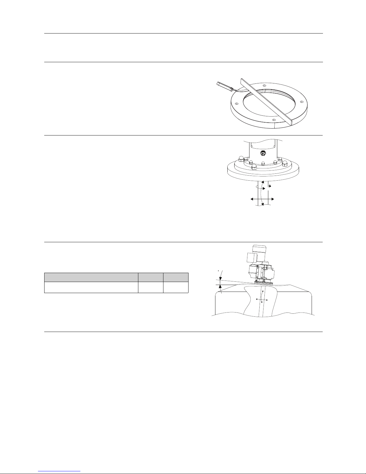
Step 2
Ensure that the flange surface flatness tolerance equals 0,1. Use a solid straight ruler and a feeler gauge to determine the flatness.
4303-0022
Step 3
Ensure that the flange will accept forces applied by the drive unit.
Torque Mv, Bending torque Mb and Side thrust Fs.
The values are depending on the chosen configuration of impeller
diameter, shaft length and the torque. The values can be
calculated as follow:
Mv = 23873 x P / n, [Nm] P is the power of the motor in
[KW]
n is the speed of the shaft in [rpm]
Mb = Fs x S / 1000, [Nm] S is the shaft length and is stated
in the agitator type description as
-Sxxxx-
Fs = 4,5 x M2 x 1000 / D, [N] D is the impeller diameter and
stated on the agitator type
description as -Pxxxx…
TD605-028
Mv
Mb
Fs
Fs
Mb
Step 4
Ensure sufficient rigidity of the tank.
Ensure that the max. bending angle (A), at loads from Step 3 does
not exceed according to below scheme
RPM: <100 >100
A° (max bending angle at applied loads): 0.1 0.05
A
TD605-213
Mb
Fs
Fs
Mb
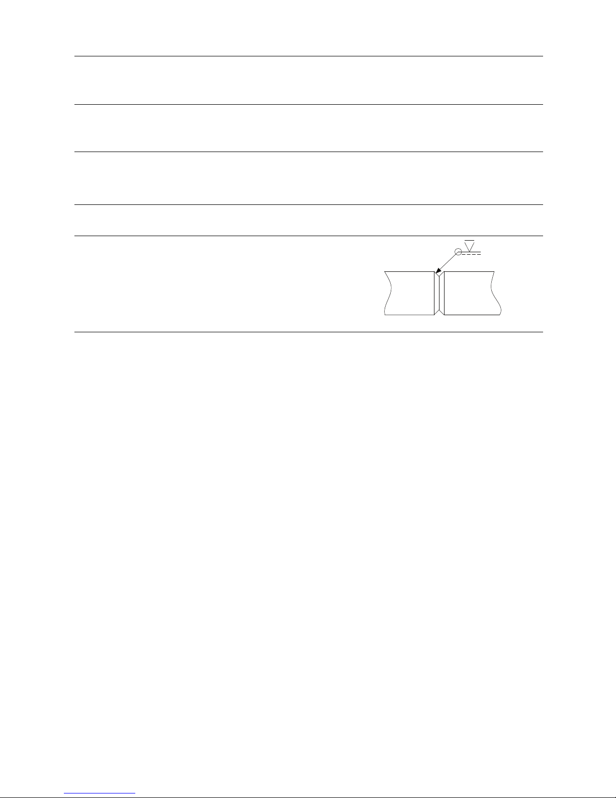
Guidelines for cutting hole in tank for Flat Shaped Welding Flange (FSWF)
CAUTION!
Alfa Laval recommend that all other welding tasks on the tank are finished before cutting the hole for the flange.
Chamfer inner and outer hole edge 45°.
12

3 Installation
Study the instructions carefully and pay special attention to the warnings!
Always check the Agitator before operation - see section 3.3 Pre-use check.
The Agitator is for permanent fastening.
Make sure that the motor correspond to the environment.
45°
45°
TD605-023
13

3 Installation
Study the instructions carefully and pay special attention to the warnings!
Always check the Agitator before operation - see section 3.3 Pre-use check.
The Agitator is for permanent fastening.
Make sure that the motor correspond to the environment.
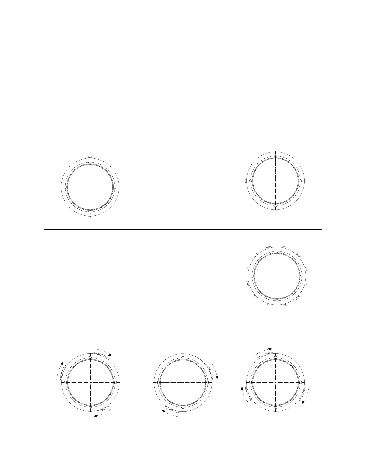
Welding procedure, flange (FSWF) without nose:
Step 1
Always allow flange to cool to ambient temperature after each section has been welded
Position the flange correctly
TD605-006
A
B
C
D
TD605-007
Step 2
Spot weld from outside.
TD605-010
A
C
D
B
Adjust alignment!
A
C
D
B
TD605-011
Step 3
Weld the following sections first from outside then from inside, and cool
with air between each section.
1
A
B
C
D
4
2
3
TD605-014
Step 4
Ensure that the surface flatness tolerance equals 0,25 after welding.
Grind and polish the welding flange.
Use a solid straight ruler and a feeler gauge to determine the flatness.
4303-0022
14
3 Installation
Study the instructions carefully and pay special attention to the warnings!
Always check the Agitator before operation - see section 3.3 Pre-use check.
The Agitator is for permanent fastening.
Make sure that the motor correspond to the environment.
Welding procedure, flange (FSWF) with nose:
NOTE!
Alfa Laval recommend a welding tool to be made and fixed to the FSWF to ensure shape and form of the FSWF during
welding and installation.
Step 1
Position the flange correctly.
Always allow flange to cool to ambient temperature after each section has been welded.
Step 2
Spot weld from outside.
TD605-214
A
C
Adjust alignment!
TD605-215
B
D
Step 3
Spot weld from inside
TD605-216
5
12
7
1
11
3
10
2
6
4
8
9
Step 4
Weld the following sections first from inside then from outside and cool to ambient temperature after each section has been
welded
Step 1 Step 2 Step 3
TD605-217
A
B
C
D
E
F
G
H
1
2
3
TD605-218
4
5
A
B
C
D
E
F
G
H
TD605-219
A
B
C
D
E
F
G
H
8
6
7
Cool with air! Cool with air! Cool with air!
15

3 Installation
Study the instructions carefully and pay special attention to the warnings!
Always check the Agitator before operation - see section 3.3 Pre-use check.
The Agitator is for permanent fastening.
Make sure that the motor correspond to the environment.
Step 5
Remove the welding tool.
Ensure that the surface flatness tolerance equals ±0.1mm.
Grind and polish the welding flange.
16
3 Installation
Study the instructions carefully and pay special attention to the warnings!
Always check the Agitator before operation - see section 3.3 Pre-use check.
The Agitator is for permanent fastening.
Make sure that the motor correspond to the environment.
Welding procedure, shaft:
NOTE!
Only relevant for divided shafts prepared for welding.
Step 1
Ensure that shaft ends are screwed completely together.
Step 2
Spot weld and cool with air.
Step 3
All-weld shaft connections according to illustration and cool with
air.
TD605-171
Step 4
Align the shaft according to shaft alignment instructions in section
6.1 Technical data.
17

3 Installation
Study the instructions carefully and pay special attention to the warnings!
Always check the Agitator before operation - see section 3.3 Pre-use check.
The Agitator is for permanent fastening.
Make sure that the motor correspond to the environment.
Mounting Agitator:
CAUTION!
Always ensure that mounting is carried out according to the assembly drawing in chapter 7 Part lists, part drawings and
service kits.
Always refer to tightening torques in section 6.1 Technical datawhen tightening bolts.
Step 1
Place impeller device(s) in the tank.
Ensure that tank and Agitator surfaces are clean
Ensure that drain (I) is pointing downwards.
II
III
I
TD605-095
Step 2
Mount the Agitator onto the tank.
NOTE!
Alfa Laval recommends using shaft retainer tool during mounting and dismantling. See section .
Step 3
(Only for ALTB machines with Intermediate steady bearing)
- Mount the intermediate steady bearing onto the shaft.
- Ensure before welding that the intermediate steady bearing is
perpendicular to the mounting flange.
TD605-137
18

3 Installation
Study the instructions carefully and pay special attention to the warnings!
Always check the Agitator before operation - see section 3.3 Pre-use check.
The Agitator is for permanent fastening.
Make sure that the motor correspond to the environment.
Step 4
Mount impeller device(s) onto shaft.
Hub diameter [mm] a - dimension [mm]
Ø30 1,1
Ø40 1,8
Ø55, Ø80, Ø120 2,8
TD605-037
3 x
3 x
TD605-038
aa
TD605-035
x 4 x 1
TD605-036
TD605-031
TD605-032
TD605-033
TD605-034
Step 5
Ensure the impeller device orientation is correct according to the direction of the desired flow. The direction is determined by the
letter "D" or "U" in the last part of the agitator type description. E.g. -P400D3P has the letter "D" which means the flow direction
is away from the drive unit. -P400U3P has the letter "U" which means the flow direction is towards the drive unit.
19

3 Installation
Study the instructions carefully and pay special attention to the warnings!
Always check the Agitator before operation - see section 3.3 Pre-use check.
The Agitator is for permanent fastening.
Make sure that the motor correspond to the environment.
Step 6
Ensure the impeller is fitted, keeping minimum radial distance
to the tank.
Further installation requirements regarding the position
can be found in 6.1 Technical data to ensure optimum
performance.
Clearence > S/15xsin(V)
NOTE!
In special cases Clearence can be reduce to 20mm+actual
deflection, please advice with Alfa Laval.
S
15
TD605-026
S
>
__
V
Clearence
Step 7
(Only when shaft is divided)
Assembleallshaftpartsasshownonthefigure.
A A
B B
TD605-024
Step 8
Align the shaft according to shaft alignment in section 6.1
Technical data.
NOTE!
When aligning shaft Alfa Laval offer guidance and direction.
20
This manual suits for next models
3
Table of contents
Other Alfalaval Mixer manuals

Alfalaval
Alfalaval ALTB-SB-20 User manual

Alfalaval
Alfalaval IM 20 User manual

Alfalaval
Alfalaval ALTB-SB-30 User manual

Alfalaval
Alfalaval IM 15 User manual

Alfalaval
Alfalaval ALS-ME-GR-30 40LF-S3 Series User manual

Alfalaval
Alfalaval ALS User manual

Alfalaval
Alfalaval LeviMag User manual

Alfalaval
Alfalaval HPM M-15 User manual

Alfalaval
Alfalaval MM UltraPure User manual

Alfalaval
Alfalaval ALTB-SB-20 User manual


