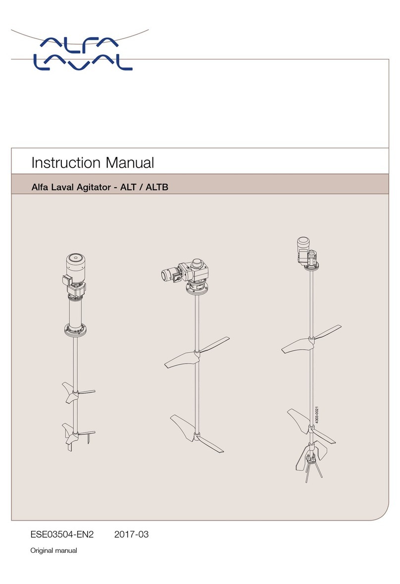
Alfalaval ALTB-SB-20 User manual

ESE03056-EN72022-11
Originalmanual
InstructionManual
ALTB-SB-20


Tableofcontents
Theinformationhereiniscorrectatthetimeofissuebutmaybesubjecttochangewithoutpriornotice
1.DeclarationsofConformity.................................................................4
2.Safety..........................................................................................6
2.1.Importantinformation.............................................................................6
2.2.Warningsigns.....................................................................................6
2.3.Inteneuse......................................................................................6
2.4.Safetyprecautions................................................................................7
3.Installation....................................................................................8
3.1.Unpacking/elivery...............................................................................8
3.2.Requirementforinstallation,personnel.........................................................9
3.3.Installation(withcutting/machininganwelingrequire).....................................9
3.4.Installation(assembling)..........................................................................13
3.5.Installation,electrically............................................................................20
3.6.Recyclinginformation.............................................................................20
4.Operation.....................................................................................21
4.1.Operation..........................................................................................21
4.2.Inspection.........................................................................................21
4.3.Troubleshooting...................................................................................21
4.4.Cleaning...........................................................................................22
5.Maintenance..................................................................................23
5.1.GeneralMaintenance.............................................................................23
5.2.Disassemblingofagitator........................................................................23
5.3.Replacementofgearmotor.....................................................................23
5.4.Replacementofseals............................................................................23
5.5.ReplacementofBearingforbottomconsole...................................................23
6.TechnicalData...............................................................................24
6.1.Technicalata.....................................................................................24
7.Partslist/Servicekits......................................................................26
7.1.ALTB-SB-20-AE(withaeration).................................................................26
7.2.ALTB-SB-20(withoutaeration)..................................................................28
7.3.ALTB-SB-20(withanwithoutaeration).......................................................29
7.4.MountingTools....................................................................................39
7.5.InstallationDrawings..............................................................................41
8.Appendix......................................................................................44
8.1.DeclarationofCompliance.......................................................................44
8.2.Orerspecific“TankWithAgitator”rawing,example........................................45
8.3.WPS................................................................................................46
8.4.Driveunitlubrication..............................................................................47
8.5.Driveunitinstruction..............................................................................52
3

1DeclarationsofConformity
EU EU
EUDeclaration Declaration
Declarationof of
ofConformity Conformity
Conformity
TheDesignateCompany
AlfaLavalKolingA/S,Albuen31,DK-6000Koling,Denmark,+4579322200
Companyname,aressanphonenumber
Herebyeclarethat
ALTB-SB
Designation
20
Type
SerialnumberfromAAC000000001toAAC999999999
isinconformitywiththefollowingirectiveswithamenments:
-MachineryDirective2006/42/EC
-RoHSDirective2011/65/EUanamenments
Thepersonauthorisetocompilethetechnicalfileisthesignerofthisocument.
GlobalProuctQualityManagerLarsKruseAnersen
TitleName
Koling,Denmark2022–11-17
PlaceDate(YYYY-MM-DD)Signature
ThisDeclarationofConformityreplacesDeclarationofConformityate2020-02-01
4

1DeclarationsofConformity
UK UK
UKDeclaration Declaration
Declarationof of
ofConformity Conformity
Conformity
TheDesignateCompany
AlfaLavalKolingA/S,Albuen31,DK-6000Koling,Denmark,+4579322200
Companyname,aressanphonenumber
Herebyeclarethat
ALTB-SB
Designation
20
Type
SerialnumberfromAAC000000001toAAC999999999
isinconformitywiththefollowingirectiveswithamenments:
-TheSupplyofMachinery(Safety)Regulations2008
-TheRestrictionoftheUseofCertainHazarousSubstancesinElectricalanElectronicEquipmentRegulations2012
Signeonbehalfof:AlfaLavalKolingA/S
GlobalProuctQualityManagerLarsKruseAnersen
TitleName
Koling,Denmark2022–11-17
PlaceDate(YYYY-MM-DD)Signature
DoCRevison_01_112022
5

2Safety
Unsafepracticesandotherimportantinformationareemphasizedinthismanual.
Warningsareemphasizedbymeansofspecialsigns.
2.1Importantinformation
Always Always
Alwaysr r
rea ea
eathe the
themanual manual
manualbefor befor
before e
eusing using
usingthe the
theagitator! agitator!
agitator!
W W
WARNING ARNING
ARNING
Inicatesthatspecialproceuresmustbefollowetoavoiseriouspersonalinjury.
CAUTION CAUTION
CAUTION
InicatesthatspecialproceuresmustbefollowetoavoiamagetotheAgitator.
NOTE NOTE
NOTE
Inicatesimportantinformationtosimplifyorclarifyproceures.
2.2Warningsigns
Generalwarning:
Causticagents:
Dangerouselectricvoltage:
2.3Intendeduse
-TheAgitatorinonlyformixing/conitioning/stirringofliquisinatank.
-TheAgitatorisonlymaefortopmountingpositiononthetopplate/welingflangeonthetank.
6

2Safety
Allwarningsinthemanualaresummarisedonthispage.
Payspecialattentiontotheinstructionsbelowsothatseriouspersonalinjuryand/ordamagetothevalveareavoided.
2.4Safetyprecautions
2.4.1 2.4.1
2.4.1Installation: Installation:
Installation:
Always Always
Alwaysreathetechnicalatathoroughly(see6TechnicalData).
Always Always
Alwaysfollowinstallationinstructionsthoroughly(see3Installation).
Never Never
NeverexposetheAgitatortounuevibrationsorshocks.
Never Never
NeverstarttheAgitatorinthewrongirectionofrotation.
Ensur Ensur
Ensure e
ethatthetankmeiaisnotcorrosivetotheAgitator.
Only Only
OnlyinstalltheAgitatorinenvironmentswithintemperaturelimit:-20°Can+40°C.
Only Only
OnlyinstalltheAgitatorinaltitueslessthan1000mabovesealevel.
Only Only
Onlyuseauthorizepersonnelwhenelectricallyequipmentisconnecte.
2.4.2 2.4.2
2.4.2Operation: Operation:
Operation:
Always Always
Alwaysreathetechnicalatathoroughly(see6TechnicalData).
Never Never
NeverstartAgitatorinthewrongirectionofrotation.
Bewar Bewar
Beware e
eofAgitatorinoperationcanproucesounlevelsinexcessof85B(A).
Always Always
Alwayshanlelyeanaciwithgreatcare.
Always Always
Alwaysrinsewellwithcleanwateraftercleaning.
Never Never
Neverruntheagitatorforalongertime(secons)withoutprouct,waterorcleaningliquiinthetank.
2.4.3 2.4.3
2.4.3Maintenance: Maintenance:
Maintenance:
Always Always
Alwaysfollowthemaintenanceinstructionthoroughly(see5Maintenance.)
Always Always
Alwaysfollowthemaintenanceinstructionforgearmotorthoroughly(see8.5Driveunitinstruction).
Always Always
Alwaysstuythepartslistanassemblyrawingcarefully(see7Partslist/Servicekits).
Never Never
NevertouchthemovingpartswhiletheAgitatorisconnectetothepowersupply.
Always Always
AlwaysisconnectthepowersupplywhileservicingtheAgitator.
Ensur Ensur
Ensure e
ecorrectrotationirectionofpropellerbeforestartupanafteranymaintainstheremighthaveimpacton
theirection.
Never Never
Neverservicetheagitatorortankwithprouctorcleaningliquiinthetank.
2.4.4 2.4.4
2.4.4T T
Transportation: ransportation:
ransportation:
Always Always
AlwaystransporttheAgitatorinoriginalpackaging.
Always Always
Alwayssupporttheshaftaequately,toprotectshaftanbearings.
Never Never
NeverexposetheAgitatortounuevibrationsorshocks.
Controlforoilleakageongearswithventscrew.
Ensurecorrectrotationirectionofimpellerbeforestartupanafteranymaintainstheremighthaveimpactonthe
irection.
7

3Installation
Theinstructionmanualispartofdelivery.Studytheinstructionscarefully.
TheAgitatorisforpermanentfastening.
akesurethemotorcorrespondstotheenvironment.
Checkthedirectionofrotationbeforeoperation.
3.1Unpacking/delivery
Always Always
AlwaysuseliftingequipmentwhenhanlingtheAgitator.
AlfaLavalcannotberesponsibleforincorrectunpacking.
Step Step
Step1 1
1
3.1.1 3.1.1
3.1.1Inspecttheeliveryforvisibletransportationamage(cratesanpackaging)-allissuesshoulbereportetocarrier.
Step Step
Step2 2
2
3.1.2 3.1.2
3.1.2Checkthateliveriesareaccoringtoeliverynotes.
CompleteAgitatorscanbeelivereinmorethanoneshipment.
Agitatorscanbeelivereasoneofthefollowing:
1.Agitatorpartsaninstructionmanualrequirefortankbuilertoinstallshaftsanpropellers.
2.Agitatorpartsaninstructionmanualrequirefortankbuilertoinstallriveunit(gearmotor)ansealingsystem.
3.As1)an2)inoneshipment.
Step Step
Step3 3
3
3.1.3 3.1.3
3.1.3InspectAgitatorpartsforvisibletransportamage.
Step Step
Step4 4
4
Do Do
DoNOT NOT
NOTuseeyeboltsongearmotortolifttheAgitator.Theyareonlyforgearmotorremoval.
Step Step
Step5 5
5
3.1.5 3.1.5
3.1.5Duringlifting:
-Alwayssupporttheshaftaequatelytoprotectshaftanbearings.
-Becarefullynottoamageshaft-enwithtreas.
-NeverexposetheAgitatortounuevibrationsorshocks.
-Controlforoilleakageongears–leaveventplugingearuntilgearisinstalleanincorrectposition.
Figur Figur
Figure e
e1, 1,
1,un un
un- -
-activate activate
activatevent vent
ventplug plug
plug
8

3Installation
Theinstructionmanualispartofdelivery.Studytheinstructionscarefully.
TheAgitatorisforpermanentfastening.
akesurethemotorcorrespondstotheenvironment.
Checkthedirectionofrotationbeforeoperation.
3.2Requirementforinstallation,personnel
W W
Weler: eler:
eler:
Experiencefromsimilartypesofinstallation,coveringTIG,MIGanMAGwelingproceuresinstainlesssteelthin
wallematerial.
Provenskillsinreainginstallationguielinesanrawingsensuringthattheinstallationiscarrieoutsafeforpersonnel
anproperty.
Er Er
Erectors: ectors:
ectors:
Experiencefromsimilartypesofinstallation.
Provenskillsinreainginstallationguielinesanrawingsensuringthattheinstallationiscarrieoutsafeforpersonnel
anproperty.
Electrician: Electrician:
Electrician:
Certifieaccoringtolocalregulationsanexperiencefromsimilartypesofinstallation.
Provenskillsinreainginstallationguielinesanrawingsensuringthattheinstallationiscarrieoutsafeforpersonnel
anproperty.
3.3Installation(withcutting/machiningandweldingrequired)
3.3.1 3.3.1
3.3.1Requir Requir
Requirement ement
ementfor for
forinstallation installation
installation
Thisworkshoulbecarrieoutbyatleasttwopersonsanforsafetyreasonsaplatformorascaffolshoulbe
establishearounthetanktop.
Duringinstallationensuretousesufficientlightning.
Thetanktopmustbehorizontallyuringinstallation–ifthatisnotthecase,alasermustbeusetoensurethatthe
rightpositionforthe“BottomConsole”canbefoun.
Ensurethatthetankoesnotcontainneitherangerousliquinorgassesanthatgooventilationisestablishe.
Alwayshavesafetyelementsremovebyauthorizepersonnel.
Nevercoverorremovenameplates.
AlwaysuseliftingequipmentwhenhanlingheavypartsoftheAgitator.
Neverconnecttopoweruringinstallation.
AlwayshavetheAgitatorconnectetopowersupplybyauthorizepersonnel.
Note:AlfaLavalhighlyrecommensinstallingmotorprotectionguartotheAgitator.
All All
Allposition position
positionnumbers numbers
numbersan an
anitem item
itemnumbers numbers
numbersr r
refer efer
eferto to
tothe the
therawings rawings
rawingsshow show
showan an
anspecifie specifie
specifiein in
in7 7
7Parts Parts
Partslist list
list/ /
/Service Service
Servicekits kits
kits
9

3Installation
Theinstructionmanualispartofdelivery.Studytheinstructionscarefully.
TheAgitatorisforpermanentfastening.
akesurethemotorcorrespondstotheenvironment.
Checkthedirectionofrotationbeforeoperation.
Step Step
Step1 1
1
3.3.2 3.3.2
3.3.2
Seeillustrationin7.5.1page41.
A.Thethree“AjustableLegForBottomConsole”pos.70arefastenetothe“BottomConsoleforAgitator”pos.74using
thethree“Screw”pos.77.
B.Theassemble“BottomConsole”froma)
“Guiespinleforbearing”pos.69
“Tool–Bushing”pos.83,
“Tool–Backstop”pos.85,
“Screw”pos.91,
“Propeller”pos.73,
“AgitatorShaft”pos.71(ifelivere),
“Propeller”pos.72(ifelivere),
“AgitatorShaft”pos.75,
arelowereintothetankanassemble.Insomecasesallthepartscanbeassembleoutsiethetankanlowereinto
thetankassemble.Allthreasmustbegreasetoensurenottoamagethethreas.
C.Accoringtotheorerspecificrawing"AgitatorwithTank"thatcomeswiththemanual(notinthemanual)thecorrect
Agitatorpositionisselecte(0/125/175mmoffcenter)whichspecifywhichpositionofholestobeuse(atainthis
manualarenottobeuse–finorerspecificrawing).
Exampleofanorerspecificrawing"Orerspecific"TankWithAgitator"rawing,example"aretobefounin8.2,page45.
D.Mountthe“ToolGuiePlate”pos.80onthe“Tankmountingflange”pos.99lettingtheshaftpos.75enteringthecorrect
holeinpos.80.The“ToolGuiePlate”mustbefastenetothetanktopusingtwoiagonallylocateholesinthetanktop.
E.Mountthe“Tool–TopGuie”pos.82tothe“ToolGuiePlate”pos.80usingthefour“Screw”pos.88.
F.Mountthe“Tool–TopGuie”pos.81intothe“Tool–TopGuie”pos.82.
G.Rotate/orientatepos.82enablingthe“Screw”pos.90tobeusetofastentheshaftinverticalirectionuringajustment
ofthe“BottomConsole”pos.74.
10

3Installation
Theinstructionmanualispartofdelivery.Studytheinstructionscarefully.
TheAgitatorisforpermanentfastening.
akesurethemotorcorrespondstotheenvironment.
Checkthedirectionofrotationbeforeoperation.
Step Step
Step2 2
2
3.3.3 3.3.3
3.3.3Seeillustrationin7.5.1page41.
A.Ifthetanktopishorizontallywithin0,5°thegravitycanbeuse
asguielineforpositionofthe“BottomConsole”–ifitisnot
possibletoajustthetanktoptohorizontallyposition(within
thetolerance)alaserpointermustbeusetoensurethatthe
rightpositionforthe“BottomConsole”isfoun.
B.TheAgitatorisliftetothecorrectpositionasshownonthe
orerspecificrawing“TankwithAgitator”thatcomeswith
themanual(notinthemanual).
Exampleofanorerspecificrawing"Orerspecific"Tank
WithAgitator"rawing,example"aretobefounin8.2,page
45.The“Screw”pos.90istightene(notmorethansufficient)
tofastentheshaftsinverticalposition.
C.Whentheagitatorshaftisincorrectpositionthethree
“AjustableLegForBottomConsole”pos.70are
ajuste/rotatefacingthetankbottomanthethree“Screws”
pos.77arefastene.Ifthelegson“BottomConsolefor
Agitator”pos.74aretoolongtheyarecuttotherequire
length.
D.Tagwelthethree“AjustableLegForBottomConsole”pos.
70tothetankbottomusingTIGweling.
E.Untightenthe“Screw”pos.90ensurethattheshaftcanrotate
freely.
F.Tightenthescrewagain.
G.Removeone“Screw”pos.77anfillthethreaholewith
weling,continueonebyonewiththetwootherscrews.
H.Removethe“Screw”anpos.90.
I.Verifythattheshaftcanrotatefreely.
J.Grintheweleseamstotherequirefinish.
Figur Figur
Figure e
e2, 2,
2,Height Height
Heightof of
ofBottom Bottom
BottomConsole Console
Console
Figur Figur
Figure e
e3, 3,
3,T T
Tightening ightening
ighteningscr scr
screws ews
ews
Figur Figur
Figure e
e4, 4,
4,W W
Weling eling
elingBottom Bottom
BottomConsole Console
Console
11

3Installation
Theinstructionmanualispartofdelivery.Studytheinstructionscarefully.
TheAgitatorisforpermanentfastening.
akesurethemotorcorrespondstotheenvironment.
Checkthedirectionofrotationbeforeoperation.
Step Step
Step3 3
3
3.3.4 3.3.4
3.3.4SeeillustrationanPartsListin7.5.1an7.5.3.
A.Usingapermanentpenoamarkinglineatposition∆1as
shownon7.5.1.page41ontheshaftpos.75.
B.Verifythatthelineisatthesameverticalpositionasthe
uppersurfaceofthetanktopflange(welingflange)pos.
99.
C.Removethe“Tool”partspos.88,82,81,80.
D.Usingtheequation:X1=“ThicknessofGasket,pos.101”
+“ThicknessofTopPlate,pos.100”,markthecuttingline
∆2.
e.g:
ThicknessofGasket=5mm
ThicknessofTopPlate=20mm
X1=5+20=25m
ifanO-ringisuseasgasketthe“ThicknessofGasket”=0
E.The“AgitatorShaft”iseliverelongerthanneeean
shoulbeshortenetonomorethan300mm.Ifitmustbe
shortenemore,theinsieiametermustbemachineto
fitthe“Shaft,UpperforAgitator”pos.76outeriameter
withina0,1mmtolerance.
F.Cutthe“AgitatorShaft”pos.75atthecuttingline∆2.
G.Pressthe“Shaft,UpperforAgitator”pos.76ontothe
“AgitatorShaft”pos.75firmlyanensurethatitisaligne
withtheshaft.
H.Welitasshownon7.5.1page41aninWPSin8.3,
page46.
I.Grintheweleseamstotherequirefinish.
Figur Figur
Figure e
e5, 5,
5,Marking Marking
Markingof of
ofpos. pos.
pos.∆ ∆
∆1 1
1
Step Step
Step4 4
4
3.3.5 3.3.5
3.3.5
A.Unscrewanisassemblytheshaftsanpropellerunit–labelallthepartscarefullywithitemnumberantanknumber.
B.Arrangecarefultransportationofthetankantheagitatorpartstotheestination.
12

3Installation
Theinstructionmanualispartofdelivery.Studytheinstructionscarefully.
TheAgitatorisforpermanentfastening.
akesurethemotorcorrespondstotheenvironment.
Checkthedirectionofrotationbeforeoperation.
3.4Installation(assembling)
3.4.1 3.4.1
3.4.1Mounting Mounting
Mountingof of
ofO O
O- -
-Rings Rings
Ringsin in
ingeneral general
general
A-
.
Applysomefoo-approvegreasetotheO-ring
Figur Figur
Figure e
e6, 6,
6,Gr Gr
Greasing easing
easingO O
O- -
-ring ring
ring
B-
.
PresstheO-ringintotheappropriategrooveatposition0°
an180°
Figur Figur
Figure e
e7, 7,
7,Inserting Inserting
InsertingO O
O- -
-ring ring
ring
C-
.
PresstheO-ringintotheappropriategrooveatposition90°
an270°
Figur Figur
Figure e
e8, 8,
8,Inserting Inserting
InsertingO O
O- -
-ring ring
ring
13

3Installation
Theinstructionmanualispartofdelivery.Studytheinstructionscarefully.
TheAgitatorisforpermanentfastening.
akesurethemotorcorrespondstotheenvironment.
Checkthedirectionofrotationbeforeoperation.
Step Step
Step5 5
5
3.4.2 3.4.2
3.4.2Seeillustrations,7.1,7.2,an7.5.3.
A.Mountthe“BearingForBottomConsole”pos.25intothe“BottomConsole”pos.74.
B.Cleanallshafts,propellersanGuieSpinel(pos.69)threasforgrease.
C.Assembletheshaftanpropellerunitinsiethetankwithgaskets,o-ringsanLoctite®:pos.24,30,35,69,71,72,73,75,
76anslieitcarefullyown/intothe“BottomConsolepos.74”withthe“BearingForBottomConsole”pos.25.
D.Avoiharbumpingagainstthebottomconsolebearing.
E.Tightenallthreastill100-200Nm.
F.Mountthe“Gasket”pos.101anthe“TopPlate”pos.100–tightwithacoupleofscrews.
G.Pressthe“SprayBallBearing”pos.26intothe“Sprayball”,pos.8.
H.Mountthe“Sprayball”pos.8(incl.the“SprayballBearing”pos.26)ontothe“Tube,CIPforSprayBall”pos.3usingthe
“Springlockforsprayball”pos.9
I.Insomecasesallthepartscanbeassembleoutsiethetankanlowereintothetankassemble.
J.Insertthe“O-Ring”pos.33intothe“Tube,CIPforSprayBall”pos.3.
K.Positionthe“Tube,CIPforSprayBall”pos.8ontothe“TopFlange”pos.100.
14

3Installation
Theinstructionmanualispartofdelivery.Studytheinstructionscarefully.
TheAgitatorisforpermanentfastening.
akesurethemotorcorrespondstotheenvironment.
Checkthedirectionofrotationbeforeoperation.
Step Step
Step6 6
6
3.4.3 3.4.3
3.4.3IfwithoutAerationgotoStep7.
IfwithAerationcontinuebelow:
Seeillustrations,7.1,7.2,an7.5.3.
A.Positionthe“Springguie”pos.7
B.Pressinthe“Pressurespring”pos.6onthe“Aerationsealbox”pos.27aninsertthetwo“O-rings”pos.34an36
usingsomefooapprovegrease.
C.Asomefoo-approvegreasetotheshaftpos.76ansliethepartsontheshaftanpositionthemasshownbelow.
15

3Installation
Theinstructionmanualispartofdelivery.Studytheinstructionscarefully.
TheAgitatorisforpermanentfastening.
akesurethemotorcorrespondstotheenvironment.
Checkthedirectionofrotationbeforeoperation.
Step Step
Step7 7
7
3.4.4 3.4.4
3.4.4Seeillustrations,7.1,7.2,an7.5.3.
A.Pressinthetwo“GuiePin”pos.13intothe“ConsoleforAgitator”,pos.4.
B.Pressinthetwo“O-ring”pos.31anpos.32intopos.4.
C.Mountthe“ConsoleforAgitator”,pos.4onthe“Tube,CIPforSprayBall”pos.3.
D.UsingtheappropriatescrewsanLoctite®,thefourwasherspos.22anfournutspos.21aresequentiallytightene
toabout200Nm.
16

3Installation
Theinstructionmanualispartofdelivery.Studytheinstructionscarefully.
TheAgitatorisforpermanentfastening.
akesurethemotorcorrespondstotheenvironment.
Checkthedirectionofrotationbeforeoperation.
Step Step
Step8 8
8
3.4.5 3.4.5
3.4.5Seeillustrations,7.1,7.2,an7.5.3.
TheMechanicalsealpos.28(28.1,28.2,28.3,28.4,28.5,28.6)consistofseveralpartsaslabellebelow–thepartscannotbe
orereseparately–onlyasonecompletemechanicallysealpos.28.
A.Asomefoo-approvegreasetotheO-ringpos.28.2anmountitonthestationarysealringpos.28.1.
B.Pressbothparts(pos.28.1anpos.28.2)intothe“Flange,Upper”pos.5.
C.Asomefoo-approvegreasetotheO-ringpos.28.4ansliesthepartspos.28.3,28.4,28.6an28.5ontotheshaft.
D.Mountthe“Flange,Upper”pos.5ontothe“ConsoleforAgitator”pos.4–ensurethatitispositionerotation-wise
asrequire.
E.Pressinthetwo“GuiePin”pos.12.
F.AsomeLoctite®tothefourscrewspos.19,mountthemwiththe“Washers”pos.16antightenthescrewssequentially
to51Nm.
G.Mountthe“ParallelKey”pos.78usingthe“Screw”pos.79.
Figur Figur
Figure e
e9, 9,
9,Gr Gr
Greasing easing
easing28.4 28.4
28.4
Figur Figur
Figure e
e11, 11,
11,28.1 28.1
28.1an an
an28.2 28.2
28.2
Figur Figur
Figure e
e10, 10,
10,28.1, 28.1,
28.1,28.1 28.1
28.1an an
an5 5
5
17

3Installation
Theinstructionmanualispartofdelivery.Studytheinstructionscarefully.
TheAgitatorisforpermanentfastening.
akesurethemotorcorrespondstotheenvironment.
Checkthedirectionofrotationbeforeoperation.
Step Step
Step9 9
9
3.4.6 3.4.6
3.4.6Seeillustrations,7.1,7.2,an7.5.3.
A.Theshaft-ensurfacepos.76anthehollowshaftsurfaceofthegearmotorpos.2arecleaneangentlygrease.
B.Thegearmotorpos.2isgentlylowereontothe“Flange,Upper”pos.5usingahoist.
C.Thescrewspos.15,washerspos.16annutspos.20aremounteusingsomeLoctite®antightenetill51Nm.
18

3Installation
Theinstructionmanualispartofdelivery.Studytheinstructionscarefully.
TheAgitatorisforpermanentfastening.
akesurethemotorcorrespondstotheenvironment.
Checkthedirectionofrotationbeforeoperation.
D.Thewasherpos.18consistsoftwopartsattachetoeachotherwithsomesiliconeasshownonthepicture.Itisimportant
thatthepartsarepositioneasshown.
E.Thebushingthatfollowsthegearmotorseenonthepictureisusetofastentheshaftintothegearmotor.
Figur Figur
Figure e
e13, 13,
13,One One
Onewasher washer
washerpos. pos.
pos.22 22
22Figur Figur
Figure e
e12, 12,
12,Bushing Bushing
Bushingfor for
forshaft shaft
shaft/ /
/gear gear
gearmotor motor
motor
F.Thescrewpos.17istightene(withoutusingLoctite®)to51Nm.
G.Thecoverthatfollowsthegearmotorismounteonthegearmotorcoveringtheshaftanbushingantightene.
H.Theoilventplugisactivateonthegearmotor(seebelowan8.5“DriveUnitInstructions”).
Figur Figur
Figure e
e14, 14,
14,Activation Activation
Activationof of
ofgear gear
gearvent vent
ventplug plug
plug
I.Useofgearmotorcoversisnotpermitteuetoriskofreucecoolingonmotor.
J.Verifythattheistancebetween“BearingforbottomConsole”pos.25topanthelowerpartof“Guiespinleforbearing”
pos.69isabout15mmasshownbelowan7.5.3“CompleteAgitatorInTank”.
Figur Figur
Figure e
e15, 15,
15,Installation Installation
Installationverification verification
verification
19

3Installation
Theinstructionmanualispartofdelivery.Studytheinstructionscarefully.
TheAgitatorisforpermanentfastening.
akesurethemotorcorrespondstotheenvironment.
Checkthedirectionofrotationbeforeoperation.
3.5Installation,electrically
-Operationbyunauthorizepersonnelmayenangerpersonnelanproperty.
-Treatallelectricalequipmentaspowere.
-Switchoffthepowerbeforemaintenanceanrepair.
-Theelectricianmustbecertifieaccoringtolocalregulationsanwithatleast3years’experiencefromsimilartypesof
installations.
-Theelectricianmusthaveprovenskillsinreainganworkingfromrawingsancablelists.
-Theelectricianmusthaveknowlegeoflocalsafetyregulationsforpoweranautomationanmakingsurethatanywork
carrieoutissafeforpersonnelanpropertybeforetheequipmentisputbackintooperation.
Ifyouneeassistanceorhavequestions–pleasecontactAlfaLaval.
-Themotorrequiresthepowersupplyasinicateonthenameplate.
-Itisrecommenetosecurethemotorwithamotorprotection.
-Werecommenstartingthemotorbyuseofasoftstarterwithastartrampuptimeof2-7.5sec.
-Werecommeninstallationofaserviceswitchattheagitatortosecurethepersonneluringservicework.
-Performavisualinspectionoftheirectionofrotation.Theirectionrequireisinicateonthenameplate.
-Rotationofagitatormustbeclockwise.Otherwisetheagitatorwillbeamage.
3.6Recyclinginformation
• •
•Unpacking Unpacking
Unpacking
-Packingmaterialconsistsofwoo,plastics,carboarboxesaninsomecasesmetalstraps.
-Wooancarboarboxescanbere-use,recycleoruseforenergyrecovery.
-Plasticsshoulberecycleorburntatalicensewasteincinerationplant.
-Metalstrapsshoulbesentformaterialrecycling.
• •
•Maintenance Maintenance
Maintenance
-Duringmaintenance,oilanwearpartsinthemachinearereplace.
-Allmetalpartsshoulbesentformaterialrecycling.
-Wornoutorefectiveelectronicpartsshoulbesenttoalicensehanlerformaterialrecycling.
-Oilanallnon-metalwearpartsmustbeisposeofinaccorancewithlocalregulations.
• •
•Scrapping Scrapping
Scrapping
-Attheenofuse,theequipmentmustberecycleaccoringtotherelevant,localregulations.Besiestheequipmentitself,
anyhazarousresiuesfromtheprocessliquimustbeconsiereanealtwithinapropermanner.Wheninoubt,orin
theabsenceoflocalregulations,pleasecontactyourlocalAlfaLavalsalescompany.
20
Other manuals for ALTB-SB-20
1
This manual suits for next models
1
Table of contents
Other Alfalaval Mixer manuals
Alfalaval
Alfalaval ESE02185-EN8 User manual

Alfalaval
Alfalaval IM 15 User manual

Alfalaval
Alfalaval IM 15 User manual
Alfalaval
Alfalaval ALT User manual
Alfalaval
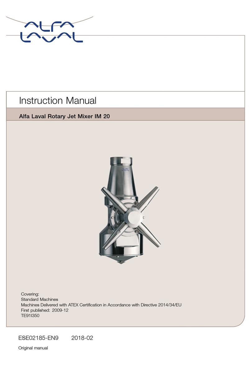
Alfalaval IM 20 User manual
Alfalaval
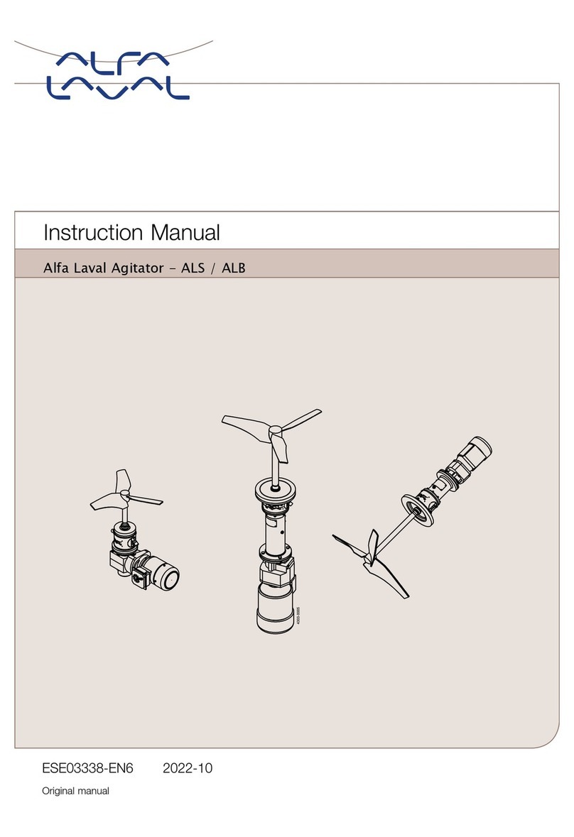
Alfalaval ALS User manual
Alfalaval
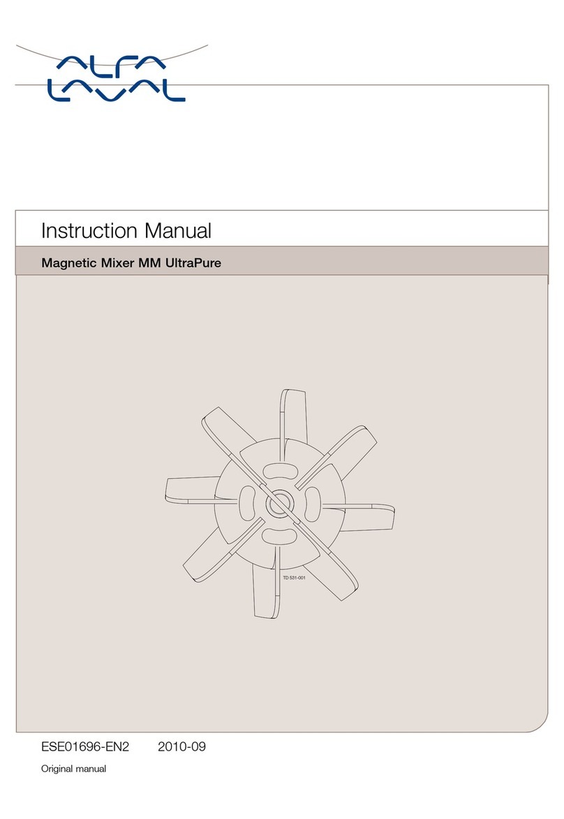
Alfalaval MM UltraPure User manual
Alfalaval
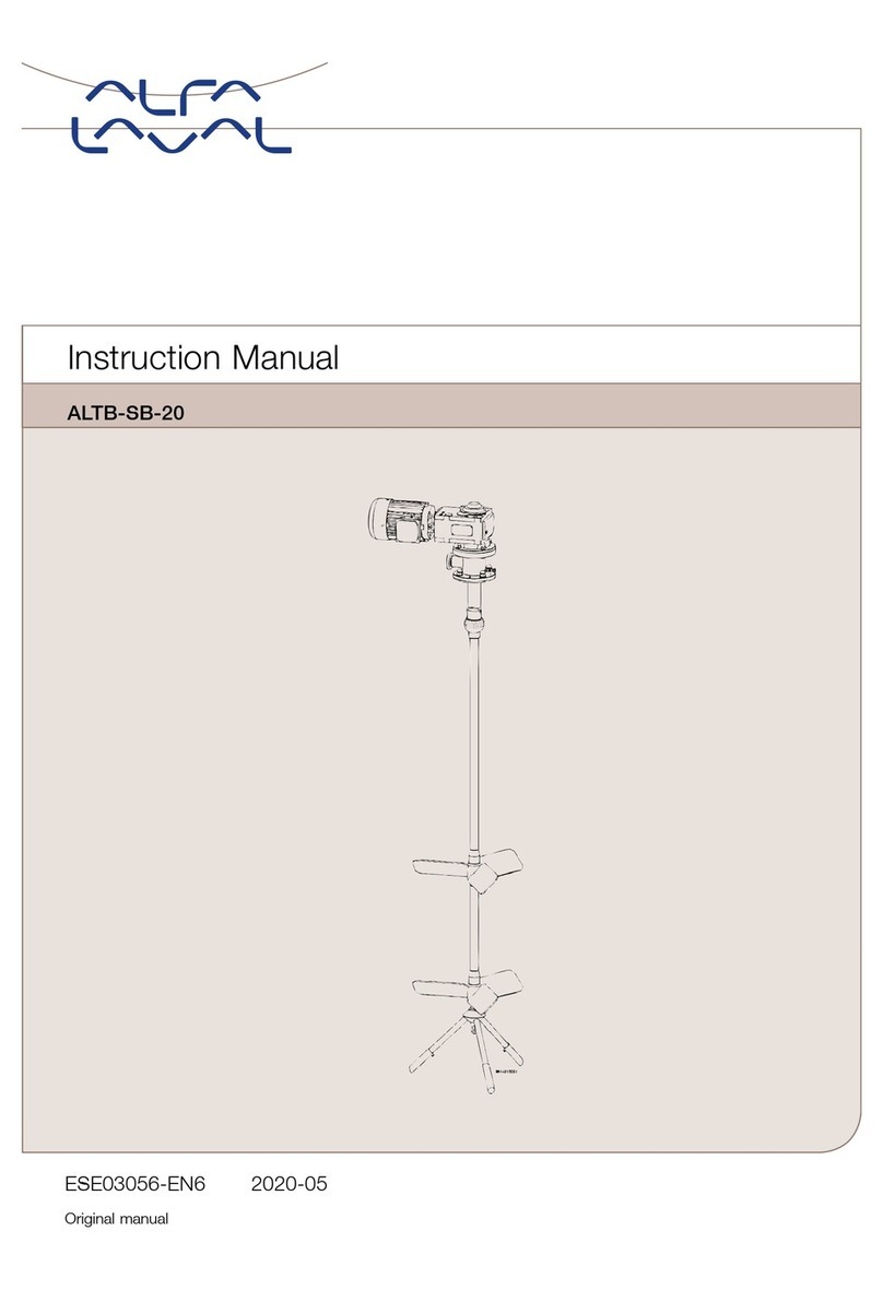
Alfalaval ALTB-SB-20 User manual
Alfalaval
Alfalaval HPM M-15 User manual
Alfalaval
Alfalaval ALS-ME-GR-30 40LF-S3 Series User manual
