Alfalaval MM UltraPure User manual
Instruction Manual
Magnetic Mixer MM UltraPure
TD 531-001
ESE01696-EN2 2010-09
Original manual


Table of contents
The information herein is correct at the time of issue but may be subject to change without prior notice
1. EC Declaration of Conformity ....................................................................... 4
2. Safety .................................................................................................... 5
2.1. Important information ............................................................................. 5
2.2. Warning signs ..................................................................................... 5
2.3. Safety precautions ................................................................................ 6
3. Installation .............................................................................................. 7
3.1. Male bearing ...................................................................................... 7
3.2. Impeller ............................................................................................ 8
3.3. Drive unit type MM338 ........................................................................... 9
3.4. Drive unit type MM434 ........................................................................... 10
3.5. Rotation Verification .............................................................................. 11
3.6. Start up ............................................................................................ 12
4. Operation ............................................................................................... 13
4.1. Mixing .............................................................................................. 13
4.2. Speeds ............................................................................................. 14
4.3. Cleaning ........................................................................................... 14
5. Maintenance ........................................................................................... 15
5.1. Dismount drive unit ............................................................................... 15
5.2. Dismount impeller ................................................................................. 16
5.3. Dismount male bearing ........................................................................... 16
5.4. Inspection ......................................................................................... 17
5.5. Replacement parts ............................................................................... 17
6. Troubleshooting ....................................................................................... 18
6.1. Troubleshooting ................................................................................... 18
7. Parts list ................................................................................................ 19
7.1. Parts list ............................................................................................ 19
3
1 EC Declaration of Conformity
The designated company
Alfa Laval
Company Name
Albuen 31, DK-6000 Kolding, Denmark
Address
+4579322200
Phone No.
hereby declare that
Magnetic Mixer MM UltraPure
Denomination Type Year
is in conformity with the following directives with amendments:
- Low Voltage Directive 2006/95/EC
- EMC Directive 2004/108/EC
- Machinery Directive 2006/42/EC
The technical construction file is kept at the above address
Manager, Product Center Fluid Handling Bjarne Søndergaard
Title Name
Alfa Laval Kolding
Company Signature
Designation
4

2 Safety
Unsafe practices and other important information are emphasized in this manual.
Warnings are emphasized by means of special signs.
Always read the manual beforeusingthemixer!
2.1 Important information
WARNING
Indicates that special procedures must be followed to avoid serious personal injury.
CAUTION
Indicates that special procedures must be followed to avoid damage to the mixer
NOTE
Indicates important information to simplify or clarify procedures.
2.2 Warning signs
General warning:
Dangerous electrical voltage:
5

2Safety
All warnings in the manual are summarized on this page.
Pay special attention to the instructions below so that severe personal injury and/or damage to the mixer are avoided.
2.3 Safety precautions
Installation:
Always read this manual thoroughly.
Always have the mixer electrically connected by authorized personnel.
Incorrect installation, mounting and use, removal of security elements, lack of inspections and maintenance and improper
connections may cause severe personal injury or property damage. Therefore it is important that the agitator is being
transported, handled, installed, started, controlled, serviced and repaired correctly exclusively by qualified personnel.
Operation:
Always read this manual thoroughly.
Ultra Clean Mixer can run dry once it has been submerged, however it is not recommended to run dry above 50 rpm.
Dry-running below 50 rpm is safe during a complete draining as well as during CIP. To avoid damage to the bearings
when running dry, please do not exceed speeds of 50 rpm.
During processes: up to max 90 oC
During CIP: up to max 95 oC–max. 50rpm
During SIP: up to max 150 oC - DO NOT RUN
Ensure that gear motor lubricate does not reach temperatures higher than 105 oC during operation, CIP or SIP.
Always handle CIP and SIP lye and acids with great care.
Maintenance:
Always read this manual thoroughly.
Always disconnect the power supply when servicing the Mixer.
Transportat ion:
Transportation of MM UltraPure unit:
Always ensure that no leakage of lubricants can occur.
Always ensure that the unit is securely fixed during transportation.
Always use original packaging or similar during transportation.
Never leave drive unit attached to weld plate during transportation.
6

3 Installation
The instruction manual is part of the delivery.
Study the instructions carefully.
3.1 Male bearing
Step 1
It is assumed that the weld plate is installed in the tank - if not, see Instruction Manual for Weld Plate for Magnetic Mixer
MM UltraPure.
Step 2
Place the male bearing with gasket in the Bearing Socket and
mount the Bearing Socket on the Removal Tool. Place the gasket
in the male bearing groove.
Bearing Socket Removal Tool Rod
TD 531-021
Step 3
Using the Bearing Socket and the Removal Tool Rod, place the
male bearing and the gasket on the weld plate threaded stub and
turn clockwise to install.
Note: For large tanks, Rod Extension may be needed to perform
installation.
Bearing Socket Removal Tool Rod
TD 531-033
Step 4
Tighten bearing until a distinct mechanical stop is reached (torque
approx. 2 Nm).
Do not over-tighten.
7
3 Installation
Warning: It is critical for the impeller to be mounted before installing the drive unit.
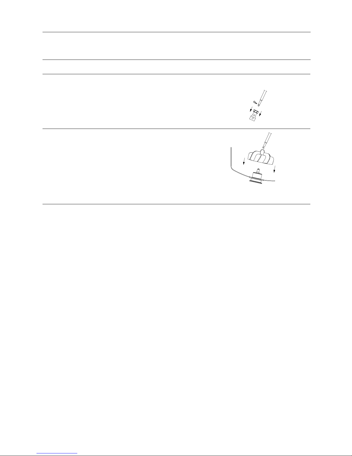
3.2 Impeller
Step 1
Always use the Removal Tool Rod. Male bearing may be damaged
if another type of tool is used.
1. Remove Bearing Socket from the end of Removal Tool Rod,
revealing a hook for handling the impeller.
TD 531-002
Step 2
1. Hook the Removal Tool Rod onto the hoop on the top of the
impeller.
2. Place the impeller carefully on the male bearing.
3. Rotate the impeller slowly by hand 360 degrees (one rotation)
ensuring that there is no collision between the impeller and
tank bottom / weld plate.
Note: Make sure the female/impeller bearing is fully set onto the
male bearing.
Warning:
Theimpellermustbemountedbefore installing the drive unit in
order not to damage the bearings.
TD 531-022
8
3 Installation
Warning: It is critical for the impeller to be mounted before installing the drive unit.
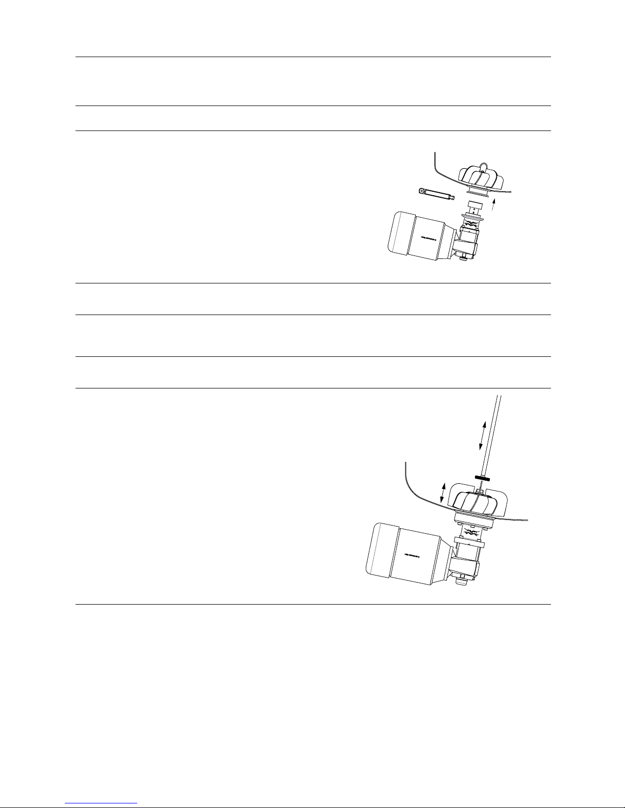
3.3 Drive unit type MM338
Step 1
Ensure the bearing and impeller is mounted before mounting the
drive unit.
Drive Unit
TD 531-034
Step 2
Gripping the drive unit firmly, align the drive unit with the weld plate and apply the clamp ring, without tightening this fully.
Step 3
Gear motor orientation can be adjusted in order for this to clear tank legs.
Tighten clamp ring (torque 20 Nm).
Step 4
Ensure the upper part of the flange is flush with the lower side of the weld plate.
Step 5
CAUTION!
!!Check for levitation!!:
Push on the impeller hoop with Removal Tool Rod handle. Impeller
should travel axially minimum 0,5 mm, otherwise it is NOT
levitated. If so, ensure bearing is completely seated and flange is
flush against the bottom of the weld plate. Lubricate the bearings
with ie. water and recheck levitation.
TD 531-035
9

3 Installation
Warning: It is critical for the impeller to be mounted before installing the drive unit.
3.4 Drive unit type MM434
Step 1
Drive Unit
Ensure the bearing and impeller is mounted before mounting the
drive unit.
TD 531-036
Step 2
Gripping the drive unit firmly, align the drive unit with the weld plate. Adjust gear motor orientation in order for this to clear
tank legs.
Step 3
Apply mounting bolts without tightening these fully.
Step 4
Making certain the weld plate and drive unit flange are completely
flush, tighten the mounting bolts to secure (torque 26 Nm).
Caution:
!!Check for levitation!!:
Push on the impeller hoop with Removal Tool Rod handle. Impeller
should travel axially 0.5-1.5 mm, otherwise it is NOT levitated. If
so, ensure bearing is completely seated and flange is flush against
the bottom of the weld plate. Lubricate the bearings with ie. water
and recheck levitation.
TD 531-035
10

3 Installation
It is recommended that the customer install an emergency stopping device and a service disconnect for their full tank/mixer
processing system
3.5 Rotation Verification
Step 1
After confirming the impeller is levitated, power up the drive unit.
Warning:
Ensure the correct power is used for the VFD and motor. Incorrect power supply can permanently damage components.
Step 2
Start up the mixer running slowly below 50 rpm and verify the
impeller is rotating clockwise.
If the impeller is rotating counter-clockwise, the drive unit must be
re-wired and re-installed so rotation is reversed.
NOISE OR VIBRATION:
If there is excessive noise or vibration please ensure:
- impeller is levitated.
- male bearing is seated correctly.
- motor flange is seated completely and flush to the tank.
- impeller is rotating clockwise.
- there is no contact between tank bottom and impeller.
- that Male Bearing has not come loose during eventual
counterclockwise rotation
- If the noise or vibration persists please contact your Alfa Laval
representative.
CAUTION:
Always disconnect drive unit before working with the impeller or
bearing.
Looking from top above mixer
TD 531-007
11

3 Installation
The ultra clean mixer should only be operated when mounted in a tank.
Never place objects or tools inside the tank when operating the mixer.
3.6 Start up
Step 1
Alfa Laval requests using a variable frequency drive, VFD, to set the mixer´s rpm - please refer to the VFD´s manual provided
with your equipment.
Step 2
If you are using your own VFD controller:
1. Always allow at least a 30 sec “soft start” during power up before reaching set speed.
2. Always run at least a 20 sec “slow stop” before coming to a full stop.
(These features are pre-programmed into controllers supplied by Alfa Laval.)
CAUTION:
The maximum rpm of the mixer is both product viscosity and tank size dependent.
Refer to quotation for max. rpm.
Step 3
Your Magnetic Mixer MM UltraPure is now installed and ready for operation.
12

4Operation
The ultra clean mixer should only be operated when mounted in a tank.
Never place objects or tools inside the tank when operating the mixer.
4.1 Mixing
Step 1
Verify the bottom valve is closed before tank is filled.
Step 2
Fill the tank with the desired amount and type of media.
Step 3
Start up the mixer according to your specific mixing requirements.
Ta nk W i th M e di a
TD 531-037
13

4Operation
The ultra clean mixer should only be operated when mounted in a tank.
Never place objects or tools inside the tank when operating the mixer.
4.2 Speeds
The allowable maximum speed for the impeller is depending on several factors such as fluid viscosity, tank dimensions, tank-
and baffle design and geometry.
The recommended maximum speeds in a fully baffled tank - mixing products with water like viscosity - are:
6" impeller: 550 RPM
8" impeller: 390 RPM
10" impeller: 185 RPM
12" impeller: 125 RPM
Excessive speeds may result in losing the magnetic coupling connection to the impeller head - recognized through vibrations and
abnormal noise. In such cases the mixer must be stopped immediately to avoid damage.
4.3 Cleaning
Step 1
For optimal performance and service life of the mixer, proper CIP and SIP procedures should be followed.
The mixer is designed for use with CIP, please study the instructions carefully and pay special attention to warnings !
Always handle CIP and SIP lye and acids with great care.
Caustic danger!
Always use rubber gloves! Always use protective goggles!
Step 2
The mixer can run at 50 rpm or less during cleaning processes. There is no need to run mixer during SIP - do NOT run
the mixer during SIP.
NOTE:
If CIP or SIP temperatures are in excess of 1500C (3000F), it is important to remove the impeller, drive unit and male bearing.
(See Section 3 for instructions on removing these components.)
14

5 Maintenance
It is critical that the drive unit is dismounted before dismounting the impeller.
5.1 Dismount drive unit
Step 1
Before maintenance, ensure the main power switch is off and power is disconnected.
Step 2
Type MM338: Loosen the clamp ring.
Type MM434: Loosen the mounting bolts.
Step 3
Make preparations for supporting the drive unit before removing clamp ring/bolts completely.
CAUTION:
The drive unit may be heavier than expected. When it becomes loose, be careful not to let it fall, since it may very well become
permanently damaged.
Type MM338 Type MM434
TD 531-038
TD 531-039
15

5 Maintenance
It is critical that the drive unit is dismounted before dismounting the impeller.
5.2 Dismount impeller
Step 1
Ensure the drive unit is removed.
Step 2
Use the Bearing SocketandRemovalToolRod:
1. Remove Bearing Socket from the end of the Removal Tool Rod,
revealing a hook for handling the impeller.
2. Hook the Removal Tool Rod onto the hoop on top of the
impeller.
3. Lift the impeller off of its bearing carefully.
TD 531-040
5.3 Dismount male bearing
Step 1
Re-install the Bearing Socket on the Removeal Tool Rod.
Step 2
Applyingthetool,thesocketgrooveshouldfitontothebearing
key (flat section on upper part of bearing).
Step 3
Make sure socket is firmly applied onto bearing before turning.
Step 4
Turn the Bearing Socket and Removal Tool Rod counter-clockwise
todismountthemalebearing.
TD 531-013
16

5 Maintenance
It is critical that the drive unit is dismounted before dismounting the impeller.
5.4 Inspection
Step 1
After a few days of operation listen for abnormal sounds. If any, dismount the mixer and check all parts for nicks and dents.
Alfa Laval recommends that the bearing and gasket should be checked for cleanability and wear after one month of operation. If
there is abnormal wear on either components, contact Alfa Laval for further instructions.
After each CIP sequence check that the mixer and parts are clean - also look for wear, check the gasket ensuring that it is
without tear or flat spots.
Step 2
Regular inspections should be performed at least every 6 months or as according to Preventative Maintenance plans.
Step 3
If any component is found damaged during inspection, please contact Alfa Laval for repair and/or replacement parts.
5.5 Replacement parts
All wear parts or damaged parts should be replaced only with Alfa Laval original components. Please contact Alfa Laval for any
replacement components needed.
17

6 Troubleshooting
6.1 Troubleshooting
Fault Possible Causes Action
1The Mixer does not
start.
Fault in power supply. Check power supply.
2 The impeller does
not rotate.
Male bearing or magnetic drive not mounted. Dismount the drive unit, detach the impeller
and mount the male bearing, impeller, magnetic
drive and drive unit.
3 Poor motor effect. Motor incorrectly connected. Incorrect power
is connected.
Check the motor connections and that the
correct power is being used. Incorrect
connections and power can cause the motor
to burn.
4Poor mixing. Impeller rotating in wrong direction. Check the installation. Check that the impeller
rotates clockwise as seen from above.
5Noise from Mixer. Incorrect installation of mixer, worn male
bearing or male bearing not tightened correctly.
1. Check that the impeller is levitated.
2. Check that the male bearing is seated
correctly.
3. Check that the motor flange is seated
completely and flush to the bottom of the
weld plate.
4. Check that the impeller is rotating clockwise.
6 Noise from drive unit. Humming sounds and a high pitch sound from
the motor at lower Hertz is normal.
If there is any clinking, ticking or rattling sounds,
please call Alfa Laval for further troubleshooting.
7Magnetic coupling
disconnected.
1. Mixer accelerating too quickly.
2. Speed too high for the current application.
1. Check start up (see Section 1.5).
2. Reduce maximum speed. Contact Alfa
Laval for recommendations on maximum or
see quotation.
8 Particles seated on
the impeller.
Magnetic particles from associated media. Check and take action with regard to the
presence of particles or contents of associated
media and raw materials. Magnetic particles
are not removed during normal cleaning.
The impeller must be removed and cleaned
separately.
9 Insufficient cleaning
of the impeller.
Poor fluid flow in impeller:
1. Due to low fluid level
2. Due to low speed.
3. Too high speed.
1. Increase the fluid level.
2. Increase RPM.
3. Reduce RPM to prevent vortex.
18

7Partslist
7.1 Parts list
Male Bearing And Gasket Weld Plate
TD 531-014
TD 531-041
Impeller Bearing Socket and Removal Tool Rod
TD 531-016
TD 531-018
Drive Unit
TD 531-042
19
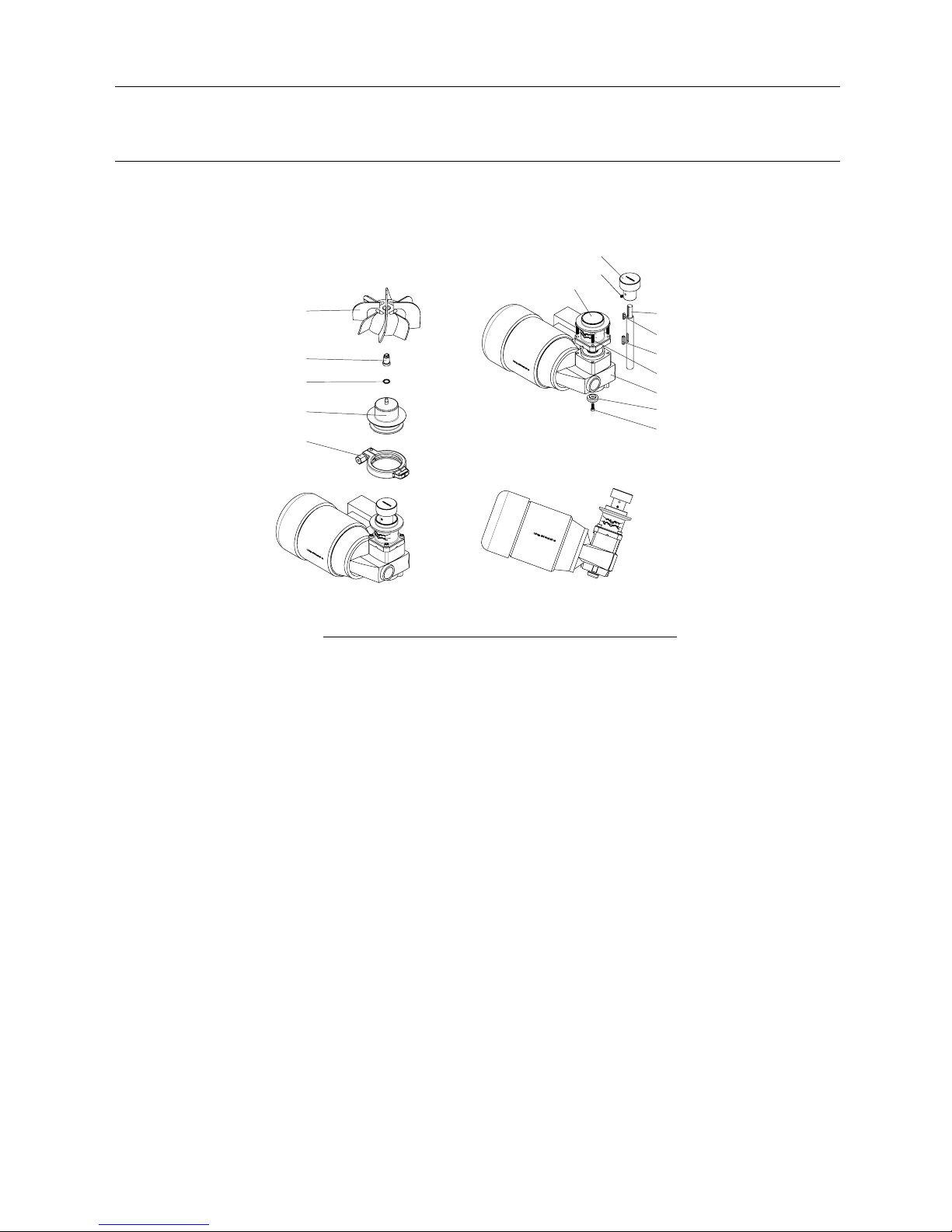
7Partslist
MM338
TD 531-043
1
2
3
4
5
6
7
11
8
9
10
12
13
14
15
Spare Parts
Pos Denomination Item number
1Impeller
2 Male bearing 9634 0861 07
3Gasket 9634 0861 09
4Weld Plate
5Clamp
6DriveRotor
7Pointed Screw
8Shaft
9 Parallel Key
10 Parallel Key
11 Flange
12 Screw
13 Fixing Element
14 Screw
15 Gear Motor
20
Table of contents
Other Alfalaval Mixer manuals

Alfalaval
Alfalaval ALS User manual

Alfalaval
Alfalaval IM 15 User manual

Alfalaval
Alfalaval IM 20 User manual

Alfalaval
Alfalaval HPM M-15 User manual

Alfalaval
Alfalaval ALTB-SB-30 User manual

Alfalaval
Alfalaval ALT User manual

Alfalaval
Alfalaval ALT series User manual

Alfalaval
Alfalaval ALTB-SB-20 User manual

Alfalaval
Alfalaval ALS-ME-GR-30 40LF-S3 Series User manual

Alfalaval
Alfalaval IM 15 User manual


