ALFAtron ALF-MUH88E User manual


ALFATRON ALF-MUH88E
Preface
Read this user manual carefully before using this product. Pictures shown in this
manual is for reference only, different model and specifications are subject to real
product.
This manual is only for operation instruction only, not for any maintenance usage. The
functions described in this version are updated till March 2017. Any changes of
functions and parameters since then will be informed separately. Please refer to the
dealers for the latest details.
All product function is valid till 2017-3-2.
Trademarks
Product model and logo are trademarks. Any other trademarks mentioned in this
manual are acknowledged as the properties of the trademark owner. No part of this
publication may be copied or reproduced without the prior written consent.
FCC Statement
This equipment generates, uses and can radiate radio frequency energy and, if not
installed and used in accordance with the instructions, may cause harmful interference
to radio communications. It has been tested and found to comply with the limits for a
Class B digital device, pursuant to part 15 of the FCC Rules. These limits are designed
to provide reasonable protection against harmful interference in a commercial
installation.
Operation of this equipment in a residential area is likely to cause interference, in which
case the user at their own expense will be required to take whatever measures may be
necessary to correct the interference
Any changes or modifications not expressly approved by the manufacture would void
the user’s authority to operate the equipment.

ALFATRON ALF-MUH88E
ALFAtron www.alfatron.co.za
SAFETY PRECAUTIONS
To insure the best from the product, please read all instructions carefully before using
the device. Save this manual for further reference.
Unpack the equipment carefully and save the original box and packing material for
possible future shipment
Follow basic safety precautions to reduce the risk of fire, electrical shock and injury
to persons.
Do not dismantle the housing or modify the module. It may result in electrical shock
or burn.
Using supplies or parts not meeting the products’ specifications may cause
damage, deterioration or malfunction.
Refer all servicing to qualified service personnel.
To prevent fire or shock hazard, do not expose the unit to rain, moisture or install
this product near water.
Do not put any heavy items on the extension cable in case of extrusion.
Do not remove the housing of the device as opening or removing housing may
expose you to dangerous voltage or other hazards.
Install the device in a place with fine ventilation to avoid damage caused by
overheat.
Keep the module away from liquids.
Spillage into the housing may result in fire, electrical shock, or equipment damage.
If an object or liquid falls or spills on to the housing, unplug the module immediately.
Do not twist or pull by force ends of the optical cable. It can cause malfunction.
Do not use liquid or aerosol cleaners to clean this unit. Always unplug the power to
the device before cleaning.
Unplug the power cord when left unused for a long period of time.
Information on disposal for scrapped devices: do not burn or mix with general
household waste, please treat them as normal electrical wastes.

ALFATRON ALF-MUH88E
ALFAtron www.alfatron.co.za
Contents
1. Introduction ................................................................................................................. 1
1.1 Brief Introduction ............................................................................................... 1
1.2 Features ............................................................................................................ 1
1.3 Package List ...................................................................................................... 2
2. Product Appearance ................................................................................................... 3
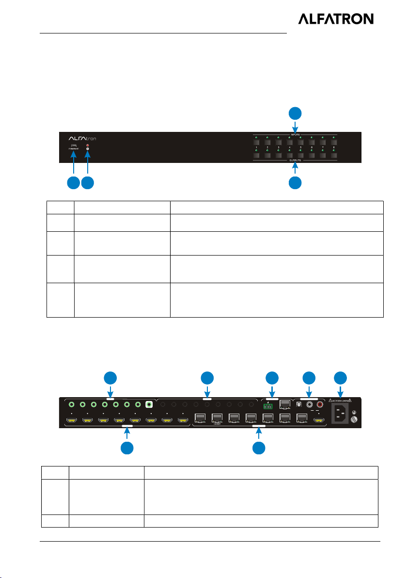
2.1 4K HDBaseT Matrix Switcher ............................................................................ 3
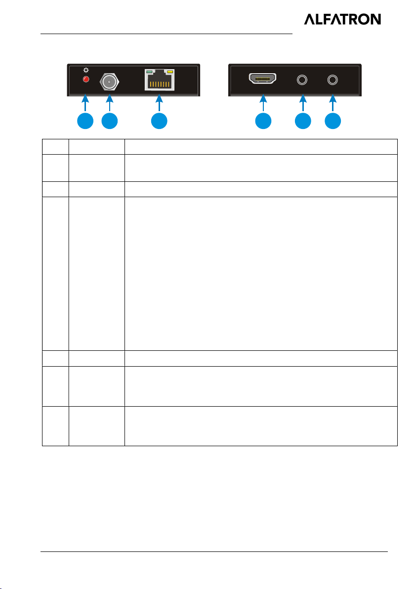
2.2 HDBaseT Receiver ............................................................................................ 5
3. System Connection ..................................................................................................... 6
3.1 System Applications .......................................................................................... 6
3.2 Connection Diagram .......................................................................................... 6
3.3 Connection Procedure ....................................................................................... 7
3.4 Connection with HDBaseT Receiver.................................................................. 7
4. System Operations ..................................................................................................... 9
4.1 IR Control .......................................................................................................... 9
IR Remote ............................................................................................... 9
Force Carrier ......................................................................................... 10
Control Far-end Device locally............................................................... 10
Control Local Device Remotely ............................................................. 11
4.2 RS232 Control ................................................................................................. 12
RS232 connection ................................................................................. 12
Installation/uninstallation of RS232 Control Software ............................ 13
Basic Settings ........................................................................................ 13
RS232 Communication Commands ...................................................... 14
4.3 TCP/IP Control................................................................................................. 23
Control Modes ....................................................................................... 23
GUI for TCP/IP control ........................................................................... 24
GUI Update............................................................................................ 27
4.4 EDID Management .......................................................................................... 28
EDID learning ........................................................................................ 28
EDID invoking ........................................................................................ 28
4.5 Firmware Update via USB ............................................................................... 29

ALFATRON ALF-MUH88E
ALFAtron www.alfatron.co.za
5. Specification ............................................................................................................. 30
5.1 4K HDBaseT Matrix Switcher .......................................................................... 30
5.2 HDBaseT Receiver .......................................................................................... 31
6. Panel Drawing .......................................................................................................... 32
6.1 4K HDBaseT Matrix Switcher .......................................................................... 32
6.2 HDBaseT Receiver .......................................................................................... 32
7. Troubleshooting & Maintenance ............................................................................... 33
8. After-sales Service .................................................................................................... 35

ALFATRON ALF-MUH88E
1
1. Introduction
1.1 Brief Introduction
This Kit is a professional 4K HDBaseT Home Distribution Hub Kit, which consists of a
4K HDBaseT Matrix Switcher, 7 HDBaseT Receivers and accessories.
The 4K HDBaseT Matrix Switcher is a professional 8x8 HDBaseT Matrix Switcher that
consist of the following inputs and outputs, 8 HDMI IN (4kx2K@60Hz signal at max), 7
IR IN, 1 IR EYE, 8 IR OUT, 1 IR OUT ALL, 7 HDBaseT OUT, 1 HDMI OUT, 1 SPDIF
OUT, 1 L&R RCA OUT, and TCP/IP, RS232 control port via phoenix connector.
The receiver is an HDBaseT Receiver that consists of the following inputs and outputs,
1 HDBaseT IN, 1 IR IN, 1 IR OUT and HDMI OUT. The receiver is powered directly by
the Matrix Switcher.
All HDMI inputs can be selected by either the front panel buttons, IR, RS232 or GUI.
The selected source is delivered to HDBaseT zoned outputs 1~7 & HDMI Output.
The Matrix Switcher is capable of delivering 4K signals up to 40m, 1080p up to 70m
and powering the receivers via a single CAT5e cable. It is however recommended to
use good quality CAT6 cable.
The Matrix Switcher supports EDID management and is HDCP 2.2, 1.4 compliant.
Audio sources can be selected via RS232 commands and TCP/IP at the Matrix
Switcher or by 3rd Party control.
1.2 Features
HDBaseT Matrix Switcher that features 7 HDBaseT outputs and 1 HDMI output
Supports HDCP 2.2, and is backwards compatible with previous version of HDCP
and HDMI
Transmits 4Kx2K @ 60Hz 4:2:0 up to 26 ft. (8m) via HDMI port and 131 ft. (40m)
via HDBaseT port
7 HDBaseT outputs with distances up to 230 ft. (70m) at 1080p and 131 ft. (40m)
at 4Kx2K on a single Cat5e/6 cable
HDBaseT Receivers are powered by the matrix using PoC technology
LED indicators show real-time switching status
Controllable via front panel, RS232, IR and TCP/IP
Built-in GUI for TCP/IP control and setup
Powerful EDID management
Support CEC to control far-end display devices via RS232 commands
Features Micro USB port for firmware upgrades

ALFATRON ALF-MUH88E
2
Easy installation with rack-mounting design, mounting hardware included
Power Supply : Matrix Unit, AC100V~ 240V; Receivers, PoC
1.3 Package List
1 x 4K HDBaseT Matrix Switcher (MUH88E)
7 x HDBaseT Receivers (TPHD-70-E-R)
1 x Power cord(Optional)
8 x IR receivers
9 x IR emitters
1 x IR remote
1 x RS232 cable(Phoenix to DB9)
2 x Mounting ears & 6 x Screws (For 4K HDBaseT Matrix Switcher )
14 x Mounting ears & 28 x Screws (For HDBaseT Receivers)
4 x Trapezoidal Plastic pads (For 4K HDBaseT Matrix Switcher)
28 x Round Plastic pads(For HDBaseT Receivers)
1 x User manual
Note: Confirm if the product and the accessories are all included, if not, please contact
with the dealers.

ALFATRON ALF-MUH88E
3
2. Product Appearance
2.1 4K HDBaseT Matrix Switcher
1. Front Panel
No. Name Description
① FIRMWARE Micro USB port for updating firmware
② Power Indicator OFF: No power;
RED: DC power present or Standby Mode.
③ INPUTS 8 input selector buttons & 8 green indicators.
numbered from “1” to “8”.
④ OUTPUTS
8 output selector buttons & 8 green indicators, press
the buttons to switch input cycle for the outputs.
Note: Pictures shown in this manual are for reference only, different model and
specifications are subject to real product.
2. Rear Panel
No. Name Description
① INPUTS
8 x HDMI inputs: Type A female HDMI connector,
connect the source device with an HDMI cable to any of
the HDMI inputs.
② OUTPUTS 7 x HDBaseT outputs: The HDBT RJ45 outputs
12
4
3
1
1
2
3
4
5
6
7
8
ALL
2 3 4 5 6 7 IR EY E
1 2 3 4 5 6 7 8 1-H DBT 3-H DBT 4-HDB T 5-HDB T 6 -HD B T 7 -HD BT
8-H DMI
Tx R x
RS2 32
8-S PDI F
L R
8
TC P/I P
IN PU TS
OUT P UT S
IR I N IR O UT
CON T RO L
AUD IO OU TPU T
1
2
3
4
5
6
7

ALFATRON ALF-MUH88E
4
deliver HD video, Audio and PoC to the HDBaseT
Receiver up to 70m.
1 x HDMI output: Connect an HDMI cable from the
Matrix Switcher to the displayer.
③ IR IN
7 x IR IN: Connect with IR receiver, fixed IR input
for the output, cannot be switched separately. It
makes up an IR bi-directional transmission with the
IR OUT on the corresponding HDBaseT receiver.
1 x IR EYE: Connect with extended IR receiver,
use the IR remote to control the Matrix Switcher.
④ IR OUT
8 x IR OUT: Plug in IR emitters to deliver the IR signal
sent from the far-end receivers connected to the
HDBaseT ports. These IR OUT sockets make up an
IR matrix with the IR IN sockets on the far-end
receivers, and all can be switched simultaneously
with the AV signal, or separately from switching. In
default setting, the 1~7 IR OUT corresponds with the
1~7 IR IN, i.e. IR OUT1 - IR IN1, IR OUT2 - IR
IN2, …IR OUT7 - IR IN7.
1 x IR ALL OUT: Plug in IR emitter to deliver the IR
signal to control input source device form any of far-
end receivers.
⑤ CONTROL
RS232: Serial port for unit control, 3-pin pluggable
terminal block, connects with control device (e.g.
PC).
TCP/IP: RJ45 port. Connect with PC for Web-
based GUI control.
⑥ AUDIO
OUTPUTS
SPDIF: Digital audio output connects directly via an
optic fibre cable to the Toslink input on a sound bar.
RCA (L&R): PCM Analogue audio output sockets
connect the de-embedded audio additional speakers.
⑦ AC100V~240V Power port, connect with power cord
Note: Pictures shown in this manual are for reference only, different model and
specifications are subject to real product.

ALFATRON ALF-MUH88E
5
2.2 HDBaseT Receiver
No. Name Description
① Power
Indicator
OFF: No power;
RED: DC power present (PoC).
② DC 12V Connect with power supply (PoC).
③ HDBaseT
IN
The RJ45 socket has two LED status indicators. Plug in the Pre-
installed CAT cable in to the HDBT RJ45 socket.
HDCP: HDCP compliant indicator
OFF: No HDMI traffic (no picture)
GREEN: Signals with HDCP.
Blinking GREEN: Signal without HDCP
LINK: HDBT Link status indicator.
OFF: No Link
YELLOW:Link Successful
Blinking YELLOW: Link Error
④ HDMI OUT Connect to HDMI display.
⑤ IR IN
Plug in the IR receiver, this will receive the IR signals from the RCU
and send through to the Matrix Switcher and then control the
desired source.
⑥ IR OUT
Plug in the IR emitter and attached to the fornt of the display, this
will send the IR signals form the Matrix Switcher to control the
display which is connected to the HDMI OUT port.
HDMI OUT
IR IN
IR OUT
LI NK HD C P
DC 12V
1
2
3
4
5
6

ALFATRON ALF-MUH88E
6
3. System Connection
3.1 System Applications
The new 4K Home Distribution Hub Kit is designed for the residential market delivering
HD Video, Audio to 4 zones with total control and simplicity.
Usage Precautions:
1) The 4K Home Distribution kit should be installed in a clean and dust free
environment.
2) Ensure that all plugs, power cords and sockets are in good condition without signs
of damage.
3) All devices should be connected before power on.
3.2 Connection Diagram
IR Emitter
PC
Speaker
Speaker
VCR
DVD
STB
Laptop
HDBaseT Receiver
IR Emitter
HDTV
HDTV
AVR Amplifier

ALFATRON ALF-MUH88E
7
3.3 Connection Procedure
1) Connect HDMI sources (e.g. DVD) to HDMI input ports of the Matrix Switcher via
good quality HDMI cables.
2) Connect the Pre-Installed CAT5e/CAT 6 cable infrastructure to Matrix Switcher
and HDBaseT receivers via good quality patch leads.
3) Connect HDTV to HDMI output port via HDMI cable.
4) Plug in an HDMI cable in to each of HDBaseT Receiver and connect to the local
display [HDTV].
5) Connect AVR amplifier to SPDIF output port or via the Toslink optic fibre cable.
6) Connect speaker to L&R (RCA) output port via audio cable.
7) Plug the IR Receivers 3.5mm jack into the IR IN sockets on HDBaseT Receivers
and plug in the IR Emitters to the IR OUT sockets (1~8) on Matrix Switcher to
make up as IR Matrix.
8) Plug the phoenix connector in to the RS232 socket on the matrix, this will enable
the Matrix Switcher to be controlled via a PC.
9) Plug in a Patch lead from the router in to the Ethernet port on Matrix Switcher to
control Matrix Switcher by TCP/IP protocol.
10) Plug in the power supply cord. Once all components have been connected and
the installation is completed, switch on the mains supply at the socket.
Note:
1. Connect HDBT ports of Matrix Switcher and far-end HDBaseT Receivers with
straight-through cable.
2. IR receivers connected to IR IN should be with carrier. If not, send
command %0900. or %0901.to activate native carrier mode or force carrier mode
in the IR matrix launched between Matrix Switcher and far-end HDBaseT Receiver.
3.4 Connection with HDBaseT Receiver
The Matrix Switcher features 7 HDBaseT outputs which support PoC technology. Plug
in the 7 RJ45 patch leads in to the HDBT outputs and connect to the pre-installed
infrastructure. Connect the HDBaseT Receivers to the pre-installed cabling via
additional patch leads. Plug the power supply in to the power socket on the matrix, the
HDBaseT Receivers will be powered by the Matrix Switcher.

ALFATRON ALF-MUH88E
8
P
o
C
Power Supply
HDBaseT Receiver(PoC)

ALFATRON ALF-MUH88E
9
4. System Operations
4.1 IR Control
IR Remote
Connect an IR receiver to the IR EYE port of the Matrix Switcher, users can control it
through the included IR remote. Here is a brief introduction to the IR remote.
①
Standby button:
Press it to enter/ exit standby mode.
②
INPUTS:
Input channel selection buttons, range from 1~8.
③
OUTPUTS:
Output channel selection buttons, range from 1~8.
④
Menu buttons:
ALL: Select all outputs.
EDID management button: Enable input port
to manually capture and learn the EDID data
of output devices.
CLEAR: Withdraw an operation like switching
output channel, learning EDID data before it
comes into effect. Meanwhile, the matrix will
return to the previous status.
ENTER: Confirm operation.
1. To convert one input to an output:
Example: Input 1 to Output 3
→ Press INPUTS 1 + OUTPUTS 3
NOTE:
Default status, on first boot up this matrix assigns the IR outputs to the
corresponding HDMI input, meaning, IR out 1 is directly associated to HDMI
input 1 and so on. When you switch an HDMI input to a different output, the
corresponding IR OUT will be switched synchronously to allow the IR
commands to be sent from the select zone back through the Matrix
INPUTS
OUTPUTS
MENU
1 2
3
45
6
7
8
1 2
3
4 5
6
7
8
ALL
EDID
CLEAR ENTER
1
2
3
4

ALFATRON ALF-MUH88E
10
Switcher to the source.
2. To convert an input to several outputs:
Example: Convert Input 2 to Output 3, 4 and 5
→ Press INPUTS 2 + OUTPUTS 3 + OUTPUTS 4 + OUTPUTS 5
3. To convert an input to all outputs:
Example: Input 1 to all Outputs
→ Press INPUTS 1 + ALL + ENTER
By using IR & HDBaseT transmission technology, the 4K HDBaseT Matrix Switcher has
some functions as follows:
1) Control far-end output device from local.
2) Control local input/output device remotely.
3) Control the Matrix Switcher locally/remotely.
Force Carrier
a) Only if the IR receiver connected to HDBaseT receiver is with IR carrier, can the
received IR signal be transferred to IR OUT port of the Matrix Switcher.
b) Only if the IR receiver connected to the Matrix Switcher is with IR carrier, can the
received IR signal be transferred to IR OUT port of the Matrix Switcher.
If the IR receiver connected to HDBaseT receiver or the Matrix Switcher is without
an IR carrier signal, send the command “%0901.” to enter infrared carrier enforcing
mode, and then IR signal can be transferred to IR OUT port.
Control Far-end Device locally
Connect an IR receiver with IR carrier to the IR IN port of the Matrix Switcher; users
can control far-end output displayer via its IR remote from local.
In that case, the IR signal is transferred via twisted pair. Only the corresponding IR
OUT port can emit control signals to the remote display.
See the figure below:

ALFATRON ALF-MUH88E
11
Control far-end device from Local
Note: The IR receiver connected to IR IN must be with IR carrier
Control Local Device Remotely
Connect IR receiver(s) to IR IN on far-end HDBT receiver(s), and IR Emitter(s) to IR
OUT port of the switcher, and use the IR Remote of local source to control the device
remotely.
1 to 1:
Connect an IR receiver to IR IN on far-end HDBT receiver, and an IR Emitter to IR
OUT port of the switcher. Use the IR Remote of local source to control the device
remotely. See below:
Control local device from remote
Note: Send command “%0901.” to enter infrared carrier enforcing mode if the IR
DVD
IR Remote
HDTV
IR Emitter
Receiver
HDTV
IR I N
IR OU THDM I OUT
TP IN
LINK H DCP
IN PU TS
OUT PU T S
IR I N I R OU T
CON TR OL
AUD IO OUT PUT
1 1 2 3 4 5 6 7 8 ALL2 3 4 5 6 7 IR EYE
1 2 3 4 5 6 7 8 1-HD BT 3-H DBT 4 -H DB T 5- HD BT 6 -HD BT
7-H DBT
8-H DM I
Tx Rx
RS2 32
8-S PD IF
L R
8
TCP /I P
DVD
IR Emitter
HDTV
IR Remote
Receiver
HDTV
IR IN
IR OUTHDMI O UT
TP IN
LINK HD CP
IN PUT S
OUTP U TS
IR IN IR OUT
CON TR OL
AU DIO OUT PUT
1 1 2 3 4 5 6 7 8 ALL2 3 4 5 6 7 IR EY E
1 2 3 4 5 6 7 8 1-HD BT 3-H DB T 4-HD BT 5-H DBT 6 -HD BT 7- HD BT 8 -HDM I
Tx Rx
RS2 32
8-SP DI F
L R
8
TCP/ IP

ALFATRON ALF-MUH88E
12
Receiver connected to IR IN of the receiver is not with carrier.
Multiple to Multiple: (IR Matrix)
The 8 “IR OUT” ports and the 7 “IR IN” ports on the far-end receivers make up a 7 x
8 IR matrix. See as below:
IR Matrix
The IR signal is sent by IR remote, then it is transferred to HDBaseT receiver, then to
corresponding zone of the matrix through the twisted pair, finally it is transferred to IR
OUT port and received by controlled device.
Switching Operation:
Sending command (reference to 4.2 RS232 Control): [x1]R[x2].
x1: Corresponding to the 8 IR OUT ports of the Matrix Switcher, the IR transmitter
connected to this port can be placed at IR receiving area of output device or the
Matrix Switcher itself.
x2: Corresponding to the zone (receive IR signal from HDBaseT receiver with IR IN
port connects with IR receiver) number of the Matrix Switcher.
→ Example: Send command “3R2.” to transfer IR signal received from zone 2 to IR
OUT port 3.
4.2 RS232 Control
RS232 connection
Except the front control panel, the Matrix Switcher can be controlled by far-end
control system through the RS232 communication port. This RS232 communication
port is a 3-pin phoenix connector. User can use the RS232 cable (Phoenix to 9-pin
IR Emitter
DVD
1 2 3 4 5
6
7
8
HDTV
Receiver 1
HDTV
IR IN IR OUTHDMI O UT
TP IN
LIN K HD CP
Receiver 2
HDTV
IR IN
IR OU T
HDMI OU T
TP IN
LIN K HDC P
Receiver 3
HDTV
IR IN
IR OU T
HDMI OU T
TP IN
LIN K
HDC P
INP UTS
OUTP UTS
IR IN IR OU T
CONT ROL
AUDI O OUTPUT
1 1 2 3 4 5 6 7 8 AL L2 3 4 5 6 7 IR EY E
1 2 3 4 5 6 7 8 1-H DBT 3-H DBT 4 -HD BT 5 -HD BT 6-H DB T 7-H DB T
8-H DMI
Tx R x
RS23 2
8-S PDI F
L R
8
TCP /IP

ALFATRON ALF-MUH88E
13
D-Sub) to connect the RS232 port to PC, see as below:
Installation/uninstallation of RS232 Control Software
Installation Copy the control software file to the computer connected with the
Matrix Switcher.
Uninstallation Delete all the control software files in corresponding file path.
Basic Settings
Firstly, connect the Matrix Switcher with an input device and an output device. Then,
connect it with a computer which is installed with RS232 control software. Double-click
the software icon to run this software.
Here we take the software CommWatch.exe as example. The icon is showed as
below:
The interface of the control software is showed as below:
PC
IN PU TS
OUT P UT S
IR I N IR O UT
CON T RO L
AUD IO OUT PUT
1 1 2 3 4 5 6 7 8 ALL2 3 4 5 6 7 IR EYE
1 2 3 4 5 6 7 8 1-HDB T 3-HD BT 4-H DBT 5-H DB T
6-H DB T
7-H DBT
8-H DM I
Tx R x
RS2 32
8-S PDI F
L R
8
TC P/I P

ALFATRON ALF-MUH88E
14
Please set the parameters of COM number, baud rate, data bit, stop bit and the parity
bit correctly, only then will you be able to send command in Command Sending Area.
RS232 Communication Commands
Note:
1) Please disconnect all the twisted pairs before sending command EDIDUpgrade[X].
2) In above commands, “[”and “]” are symbols for easy reading and do not need to be
typed in actual operation.
3) Please remember to end the commands with the ending symbols “.” and “;”.
4) Type the command carefully, it is case-sensitive.
Baud rate: 9600 Data bit: 8 Stop bit: 1 Parity bit: none
Command Function Feedback Example
System Commands
/*Type; Inquire the models information. XXXX
/%Lock; Lock the front panel buttons on the
Matrix. System Locked!
Monitoring area, indicates
whether the command
sent works.
Command Sending area
Parameter Configuration area

ALFATRON ALF-MUH88E
15
Command Function Feedback Example
/%Unlock; Unlock the front panel buttons on the
Matrix. System Unlock!
/^Version; Inquire the version of firmware VX.X.X
Demo.
Switch to the “demo” mode, convert
input and output in turn like1B1,
1B2, …4B3, 4B4, 1B1… and so
on .The switching interval is 2
seconds.
Demo Mode
AV:01->01
IR:01->01
AV:01->02
IR:01->02
……
AV:08->08
IR:07->07
……
Operation Commands
[x]All. Transfer signals from the input
channel [x] to all output channels X To All. (X=01~08)
All#.
Transfer all input signals to the
corresponding output channels
respectively like 1->1, 2->2…
All Through.
All$. Switch off all the output channels. All Closed.
[x]#. Transfer signals from the input
channel [x] to the output channel [x]. X Through. (X=01~08)
[x]$. Switch off the output channel [x]. X Closed. (X=01~08)
[x]@. Switch on the output channel [x]. X Open. (X=01~08)
All@. Switch on all output channels. All Open.
[x1]V[x2], [x3], [x4].
Transfer the AV signal from the input
channel [x1] to one or several output
channels [x2], [x3], [x4], separate
output channels with comma).
AV: X1-> X2
(X1/X2/X3...=01~08)
[x1]B[x2], [x3], [x4].
Transfer the AV and IR signal from
input channel [x1] to one or several
output channels ([x2], [x3], [x4]
separate output channels with
comma).
AV: X1-> X2
(X1/X2/X3...=01~08)
[x1] R[x2]. Transfer the IR signal from output
[x1] to input [x2].
IR: X1-> X2(X1 、
X2=01~08)
Status[x]. Check the I/O connection status of AV: Y-> X
Table of contents
Other ALFAtron Matrix Switcher manuals

ALFAtron
ALFAtron MUH88TP-N User manual

ALFAtron
ALFAtron ALF-MMX88A-N User manual

ALFAtron
ALFAtron MUH88TP-N User manual

ALFAtron
ALFAtron MUK44A-N User manual

ALFAtron
ALFAtron ALF-MUH88A-N User manual

ALFAtron
ALFAtron ALF-MUH88TP-N User manual

ALFAtron
ALFAtron ALF- MUH44E User manual

ALFAtron
ALFAtron ALF-MMX6464A-N User manual

ALFAtron
ALFAtron ALF-MUK88A-N User manual

ALFAtron
ALFAtron ALF-MUH44A-RS User manual