7–21
Catalog 5-1773450-5 Dimensions are in inches and Dimensions are shown for USA: 1-800-522-6752 South America: 55-11-2103-6000
Revised 9-08 millimeters unless otherwise reference purposes only. Canada: 1-905-470-4425 Hong Kong: 852-2735-1628
specified. Values in brackets Specifications subject Mexico: 01-800-733-8926 Japan: 81-44-844-8013
www.tycoelectronics.com are metric equivalents. to change. C. America: 52-55-1106-0803 UK: 44-8706-080-208
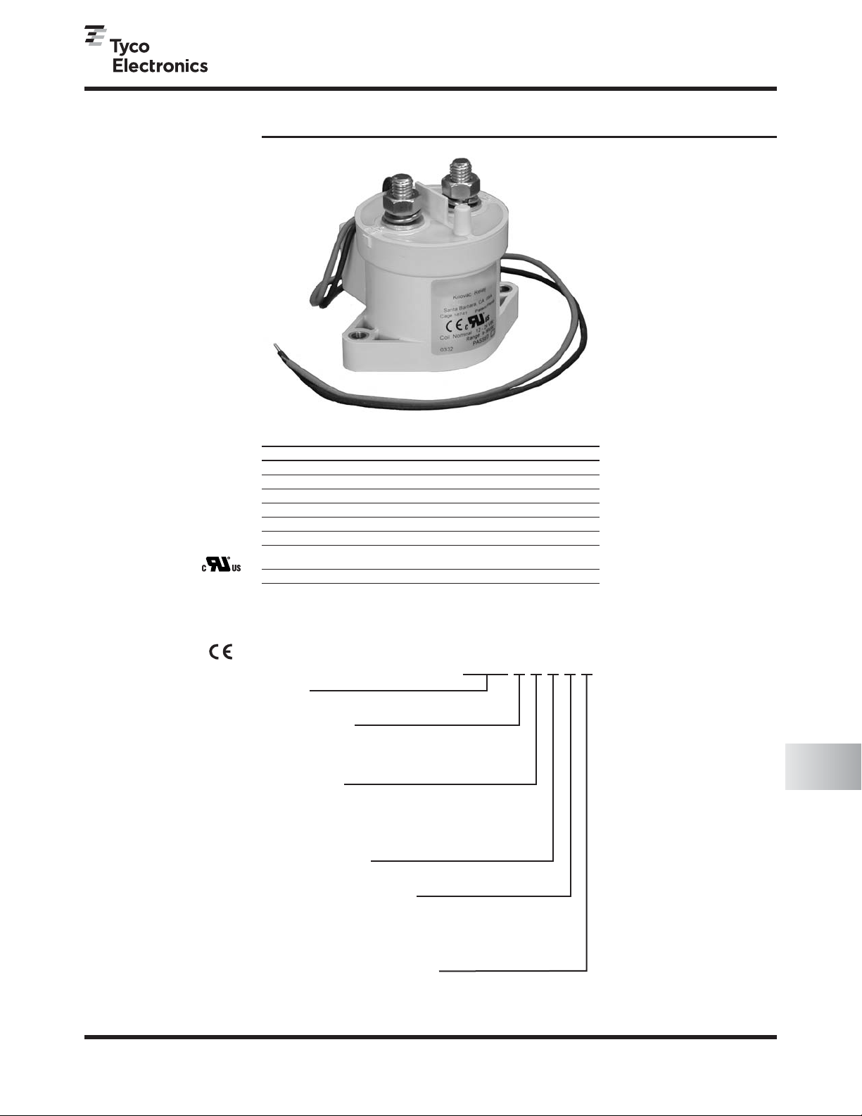
KILOVAC High Voltage DC Contactors
KILOVAC High Voltage
DC Contactors
7
KILOVAC EV200 Series Contactor With 1 Form X (SPST-NO)
Contacts Rated 500+ Amps, 12-900 Vdc
EV200 Series Contactor
(CZONKA Relay, Type III)
Product Facts
IDesigned to be the
smallest, lightest weight,
lowest cost sealed contactor
in the industry with its
current rating (500+A carry,
2000A interrupt at 320VDC)
IBuilt-in coil economizer —
only 1.7W hold power @
12VDC and it limits back
EMF to 0V. Models requiring
external economizer also
available
IOptional auxiliary contact
for easy monitoring of
power contact position
IHermetically sealed —
intrinsically safe, operates
in explosive/harsh
environments with no
oxidation or contamination
of coil or contacts, during
long periods of non-
operation
IVersatile coil/power
connections
IUL Recognized
for the U.S. and
Canada (File E208033)
All contact ratings & coil
versions may not be UL
Recognized
ICE marked for
EC applications
IAIAG QS9000 designed,
built and approved
Performance Data
Contact Arrangement, Power
Contacts — 1 Form A (SPST-NO)
Rated Operating Voltage —
12 - 900 VDC
Continuous (Carry) Current,
Typical — 500 A @ 85°C, 400 mcm
conductors
Consult Factory for required conductors
for higher (500+ A) currents
Make/Break Current at Various
Voltages 1— See graph next page
Break Current at 320VDC 1—
2,000 A, 1 cycle 3
Contact Resistance, Typ.
(@200A) — 0.2 mohms
Load Life — See graph next page
Mechanical Life — 1 million cycles
Contact Arrangement, Auxiliary
Contacts — 1 Form A (SPST-NO)
Aux. Contact Current, Max. —
2A @ 30VDC / 3A @ 125VAC
Aux. Contact Current, Min. —
100mA @ 8V
Aux. Contact Resistance, Max. —
0.417 ohms @ 30VDC /
.150 ohms @ 125VAC
Operate Time @ 25°C —
Close (includes bounce), Typ. — 15 ms
Bounce (after close only), Max. — 7 ms
Release (includes arcing),
Max @ 2000A — 12 ms
Dielectric Withstanding Voltage —
2,200 Vrms @ sea level (leakage <1mA)
Insulation Resistance @ 500VDC —
100 megohms 2
Shock, 11ms 1/2 Sine, Peak,
Operating — 20 G
Vibration, Sine, 80-2000Hz.,
Peak — 20 G
Operating Ambient Temperature —
-40°C to +85°C
Weight, Nominal — .95 lb. (.43 kg)
Notes:
1Main power contacts
250 at end of life
3Does not meet dielectric & IR after
test, 1700 amp for unit with Aux.
Contacts
Coil Operating Voltage (Valid Over Temperature Range)
Voltage (Will Operate) 9-36VDC 32-95VDC 48-95VDC
Voltage (Max.) 36VDC 95VDC 95VDC
Pickup (Close) Voltage Max. 9VDC 32VDC 48VDC
Hold Voltage (Min.) 7.5VDC 22VDC 34VDC
Dropout (Open) Voltage (Min.) 6VDC 18VDC 27VDC
Inrush Current (Max.) 3.8A 1.3A 0.7A
Holding Current (Avg.) 0.13A@12V,
0.07A@24V 0.03A@48V 0.02A@72V
Inrush Time (Max.) 130ms 130ms 130ms
Ordering Information
Typical Part Number 䊳EV200AAANA
Series:
EV200 = 500+ Amp, 12-900VDC Contactor
Contact Form:
A = Normally Open
H = Normally Open with NO Aux. Contacts
G = Normally Open with NC Aux. Contacts
Coil Voltage:
A = 9-36VDC (1 = requires external coil economizer)
D = 32-95VDC (2 = requires external coil economizer)
J = 48-95VDC (3 = requires external coil economizer)
R = 28VDC with Mechanical Economizer
Coil Wire Length:
A = 15.3 in (390 mm)
Coil Terminal Connector:
N = None
C = Molex Mini-fit Jr, 2 Skt, Female 18-24,
P/N 39-01-2020 & 39-00-0060 +red is pin 1
(A length only)
Mounting & Power Terminals:
A = Bottom Mount & Male 10mm x M8 Terminals
For factory-direct application assistance,
dial 800-253-4560, ext. 2055, or
805-220-2055.


