ALGE-Timing Windspeed WS2 User manual

Version-E171009
Manual

Windspeed WS2
Page 2
Important Information
General
Before using your ALGE-TIMING device read the complete manual carefully. It is part of the device and
contains important information about installation, safety and its intended use. This manual cannot cov-
er all conceivable applications. For further information or in case of problems that are mentioned not at
all or not sufficiently detailed, please contact your ALGE-TIMING representative. You can find contact
details on our homepage www.alge-timing.com
Safety
Apart from the information of this manual all general safety and accident prevention regulations of the
legislator must be taken into account.
The device must only be used by trained persons. The setting-up and installation must only be exe-
cuted according to the manufacturer’s data.
Intended Use
The device must only be used for its intended applications. Technical modifications and any misuse
are prohibited because of the risks involved! ALGE-TIMING is not liable for damages that are caused by
improper use or incorrect operation.
Power supply
The stated voltage on the type plate must correspond to voltage of the power source. Check all con-
nections and plugs before usage. Damaged connection wires must be replaced immediately by an
authorized electrician. The device must only be connected to an electric supply that has been installed
by an electrician according to IEC 60364-1. Never touch the mains plug with wet hands! Never touch
live parts!
Cleaning
Please clean the outside of the device only with a smooth cloth. Detergents can cause damage. Never
submerge in water, never open or clean with wet cloth. The cleaning must not be carried out by hose
or high-pressure (risk of short circuits or other damage).
Liability Limitations
All technical information, data and information for installation and operation correspond to the latest
status at time of printing and are made in all conscience considering our past experience and
knowledge. Information, pictures and description do not entitle to base any claims. The manufacturer
is not liable for damage due to failure to observe the manual, improper use, incorrect repairs, technical
modifications, use of unauthorized spare parts. Translations are made in all conscience. We assume
no liability for translation mistakes, even if the translation is carried out by us or on our behalf.
Disposal
If a label is placed on the device showing a crossed out dustbin on wheels (see drawing),
the European directive 2002/96/EG applies for this device.
Please get informed about the applicable regulations for separate collection of electrical and
electronical waste in your country and do not dispose of the old devices as household
waste. Correct disposal of old equipment protects the environment and humans against
negative consequences!
Copyright by ALGE-TIMING GmbH
All rights reserved. Any duplication, either in full or in part, requires the prior written consent of the
copyright holder.
Subject to changes! Copyright by:
ALGE-TIMING GmbH
Rotkreuzstrasse 39
A-6890 Lustenau
Austria
office@alge-timing.com
www.alge-timing.com
Windspeed WS2
Page 3
Table of contents
1General ....................................................................................................................................... 4
1.1 System components:................................................................................................................... 4
2Implementing ............................................................................................................................. 4
3Set Up of the System................................................................................................................. 5
3.1 Anemometer with Timy................................................................................................................ 5
3.2 Anemometer with OPTIc2 and OCD2 ......................................................................................... 5
3.3 Anemometer with OPTIc2 ........................................................................................................... 6
3.4 Anemometer with Timy and Photofinish System......................................................................... 6
3.5 Anemometer with Radio System WTN-WS................................................................................. 7
4Mounting of the anemometer WS2 .......................................................................................... 9
5Operation of the anemometer WINDSPEED WS2................................................................... 9
5.1 Display indication....................................................................................................................... 10
6Settings for the Displayboard ................................................................................................ 10
6.1 D-LINE Scoreboards ................................................................................................................. 10
6.2 GAZ Scoreboards...................................................................................................................... 10
7Technical details...................................................................................................................... 11
7.1 Circuit points.............................................................................................................................. 11
8Treatment of the sensor.......................................................................................................... 11
8.1 Very important ........................................................................................................................... 11
Subject to changes!
Copyright by ALGE-TIMING GmbH
Rotkreuzstrasse 39
A-6890 Lustenau
Austria
www.alge-timing.com

Windspeed WS2
Page 4
1 General
The ALGE WINDSPEED (WS2) functions with a colorimetric mass flow sensor. This
enables fast and exact wind measurement.
The miniaturzed colorimetric mass flow sensor features an exceptionally dynamic.
Based on the light involved masses of the sensors and the thermical influenced sur-
rounding, for the measurements needed, time constant will be achieved in a range of
under 1ms in dependance of the used media.
The ideal design of the wind pickup sensor and the fast reaction time for a measure-
ment guarantee that no change of wind will appear between the measurings. Viz in a
measuring for athletics, the time will be measured for 10 seconds. The more measur-
ings will follow in this time, the more exactely the average value for this period will be.
Due to the fact that no mechanical parts are used, the WS2 should never be calibrat-
ed. The calibration happens one time before delivery to the customer, after that the
device will retain its features forever. Annoyance influences through humidity or
thermal fluctuations are not excisting.
The WS2 is also supremely robust. Even a drop to the floor of the measuring unit
shouldn’t cause any functions annoyances.
It is very important, that the air supply through the tubes is always ensured in the
same way, that means that the tubes must not be plugged.
1.1 System components:
• Wind measuring device WINDSPEED WS2
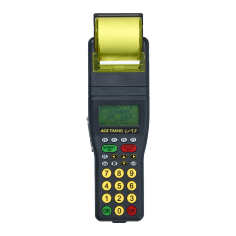
• Terminal TIMY
• Cable reel KT-WS100 with 100m cable (wind measuring device to terminal or
PC)
• Tripod TRI128
Option:
• Case with foam plastic inlay K12
• USB-RS485 adapter (for PC-Connection)
• Displayboard
WINDSPEED WS2-TY (with terminal TIMY):
Advantages:
• Timy has got all interfaces.
• Usage of anemometer at long jump
• Simple connection of the display board
2 Implementing
See Timy manual “GENERAL”

Windspeed WS2
Page 5
3 Set Up of the System
There are several possibilities to connect the Windspeed WS2 to a photofinish. Of course
you can use the Windspeed WS2 as well without photofinish with a Timy2 or Timy3 for long
jump and triple jump.
3.1 Anemometer with Timy
The Timy2 or Timy3 is connected by cable 246-02 and cable reel KT245K10 with the ane-
mometer WS2. This configuration you use for long jump or triple jump.
3.2 Anemometer with OPTIc2 and OCD2
The Timy2 or Timy3 is connected by cable 246-02 and cable reel KT245Z10 with the ane-
mometer WS2. The distribution box OCD2 is connected by IEEE1394 cable with the PC and
the photo finish camera OPTIc2 is connected to OCD2 e.g. by cable 260-10.

Windspeed WS2
Page 6
3.3 Anemometer with OPTIc2
In this configuration the Timy is connected directly via USB-Cable to the photo finish com-
puter.
3.4 Anemometer with Timy and Photofinish System
The Timy2 or Timy3 is connected by cable 246-02 and cable reel KT245K10 with the ane-
mometer WS2. The photofinish camera OPTIc2 is connected to the PC by IEEE1394 cable.

Windspeed WS2
Page 7
3.5 Anemometer with Radio System WTN-WS
The anemometer WS2 communicates with the Timy3 W by radio. The power supply for the
WS2 and WTN-WS comes from the wind display board D-LINE.

Windspeed WS2
Page 8
The anemometer WS2 communicates with the Timy3 W by radio. The power supply for the
WS2 and WTN-WS comes from an external supply (e.g. Battery Backup Device BBG or 12V
battery).

Windspeed WS2
Page 9
4 Mounting of the anemometer WS2
Dismantle the interlock (1) of the tripod-legs and pull
them out totally. Now interlock the tripod-legs.
The tripod-middle-part (2) must be completely insert-
ed
Screw the provided intermediate-piece (3) on the tri-
pod-middle-part and put the anemometer WIND-
SPEED
WS2 (4) afterwards on the top.
Remove the protection rings (5) and connect the pro-
vided cable.
If the mounting is correctly, the distance between
ground and middle of wind catcher shall be approxi-
mately 1,22m.
!! Attention – The arrow, located on the upside of
the anemometer, must always show into the run-
ning direction !!
5 Operation of the anemometer WINDSPEED WS2
The handling of the program is very easy. As soon as all components are connected,
you just have to chose the desired wind-measuring-type.
F0 Normal
Measures the wind-speed continuously. This mode is used before the run or
sprint starts.
F1 100 m / 200 m / 75 m / 80 m H
Measures the average speed for 10 seconds. This mode is used for all sprint-
runs from 75m on (except 100m hurdles or 110m hurdles).
F2 110 m H / 100 m H
Measures the average speed for 13 seconds. This mode is used for 100m
hurdles or 110m hurdles.
F3 Jump / < 75m
Measures the average speed for 5 seconds. This mode is used for all sprint-
runs under 75m.
If the anemometer is connected to the ALGE Photofinish-system OPTIc, a manual
handling is not applicable. The software of OPTIc adopt the handling automatically.
1
5
4
3
2

Windspeed WS2
Page 10
5.1 Display indication
In this display of the TIMY, different info-
mation are shown. The line below (1)
shows the 4 different types of measuring.
The 5-digit figure on the right side (2) indi-
cates, how many measurements the
WINDSPEED has sent to the TIMY. Central
left will show the measured windspeed (3).
If a measurement is carried out, occurs the
indication of the measurement period in-
stead of „0.0 m/s“.
6 Settings for the Displayboard
6.1 D-LINE Scoreboards
For D-LINE scoreboards use the following settings [parameters].
D-LINE with version 3.6 and higher:
6-digit Scoreboard:
SEt2
t000
Ad00
D-LINE with version 3.6 and higher:
6-digit Scoreboard:
St2
t00
A00
D-LINE with version 3.5 and lower:
3-digit Scoreboard
S E 2
A 0 0
1 1 5
1:1 0
2 1 6
2:1 7
3 1 8
D-LINE with version 3.5 and lower:
6-Digit Scoreboard:
SEE2
T000
Ad00
1 00
1:00
2 00
2:00
3 15
3:10
4 16
4:17
5 18
5:00
6 00
6.2 GAZ Scoreboards
Adjust the thumb wheel switch to position 0. The toggle-switch has to be on middle position.
1
2
3

Windspeed WS2
Page 11
7 Technical details
7.1 Circuit points
1 Data for WIND-GAZ
2 Data WS2 – TIMY
8 Treatment of the sensor
The sensor does not need cleaning or auxiliary treatment during its entire lifetime!
8.1 Very important
Never clean the sensor with a pipe cleaner, cotton bud, compressed air or something like
that. Use your mouth to blow the dirt away.
1.....RS485A
2.....RS485B
3.....GND
4.....+5Volt
5.....WIND GAZ
Pin Assignment:
Table of contents
Other ALGE-Timing Measuring Instrument manuals

ALGE-Timing
ALGE-Timing Timy Commander User manual

ALGE-Timing
ALGE-Timing Speedy 150-3-R User manual

ALGE-Timing
ALGE-Timing Photocell PR1a User manual

ALGE-Timing
ALGE-Timing Timy SPEED User manual

ALGE-Timing
ALGE-Timing OPTIc2 User manual

ALGE-Timing
ALGE-Timing Photocell PR1aW User manual

ALGE-Timing
ALGE-Timing Timy SPEED User manual
Popular Measuring Instrument manuals by other brands

Klein Tools
Klein Tools CL900 instruction manual

ICM Controls
ICM Controls ICM450 Installation, operation & application guide

Teledyne Lecroy
Teledyne Lecroy WaveMaster 8000HD Getting started guide

Tonghui Electronics
Tonghui Electronics TH1991 Operation manual

ISOIL
ISOIL SBM 150 Operator's manual

KING
KING 7430 Series installation instructions