manuals.online logo
Brands
  1. Home
  2. •
  3. Brands
  4. •
  5. Aliaxis
  6. •
  7. Irrigation System
  8. •
  9. Aliaxis RXP K-Line G-Set User manual

Aliaxis RXP K-Line G-Set User manual

K-Line™ G-Set™ Irrigation
Solid Set Irrigation for pasture
Installation and user manual
RX PLASTICS LTD
PO Box 360 Ashburton
Phone +64 3 307 9081
Email [email protected]
www.rxplastics.co.nz
August 2017
2
K-Line™ G-Set™ irrigation
G-Set is a solid set fixed system that minimises “labour” for
the day to day operation of irrigation.
It is suitable for all land areas, and is not restricted by the
shape, terrain, size or topography.
Due to this flexibility, there are numerous configurations
of valves, pressure regulation and sprinkler selection to
accommodate the various design requirements.
These installation instructions apply to all of these options.
RX Plastics has developed two “control” options to operate
the system.
The first is a wireless radio mesh system (IPC) of control
which allows the operator to communicate with the units
remotely from any point from which a single unit is visible.
With this system we do not require direct line of sight to
all of the units.
The second is an individual, battery operated control
(C1013). These units need to be synchronised and
programmed prior to installation and any future adjustment
must be done individually or on a group basis.
This installation manual is a guide to the best practice of
installing G-Set. Failure to follow these instructions can
lead to instability and poor performance.
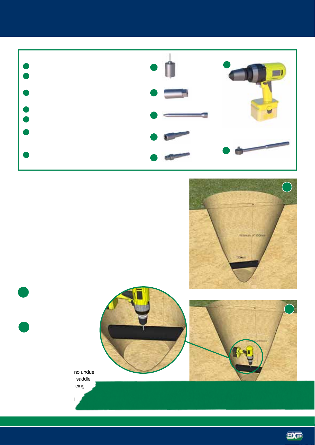
G-Set installation 3
Pipe exposure and saddle installation.
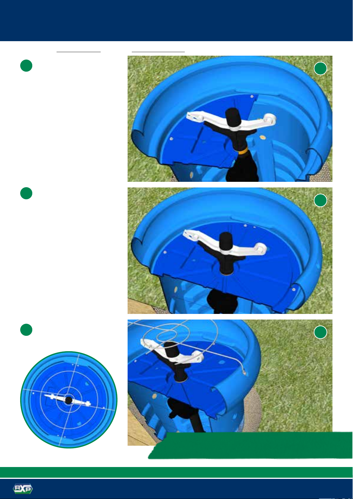
Standard G-Set installation 4
Side Entry G-Set installation 5
Completing the G-Set installation 6
Wireless Controller (IPC)
mounting instructions 7 – 12
Guides to ensure you get the optimum
performance from your IPC.
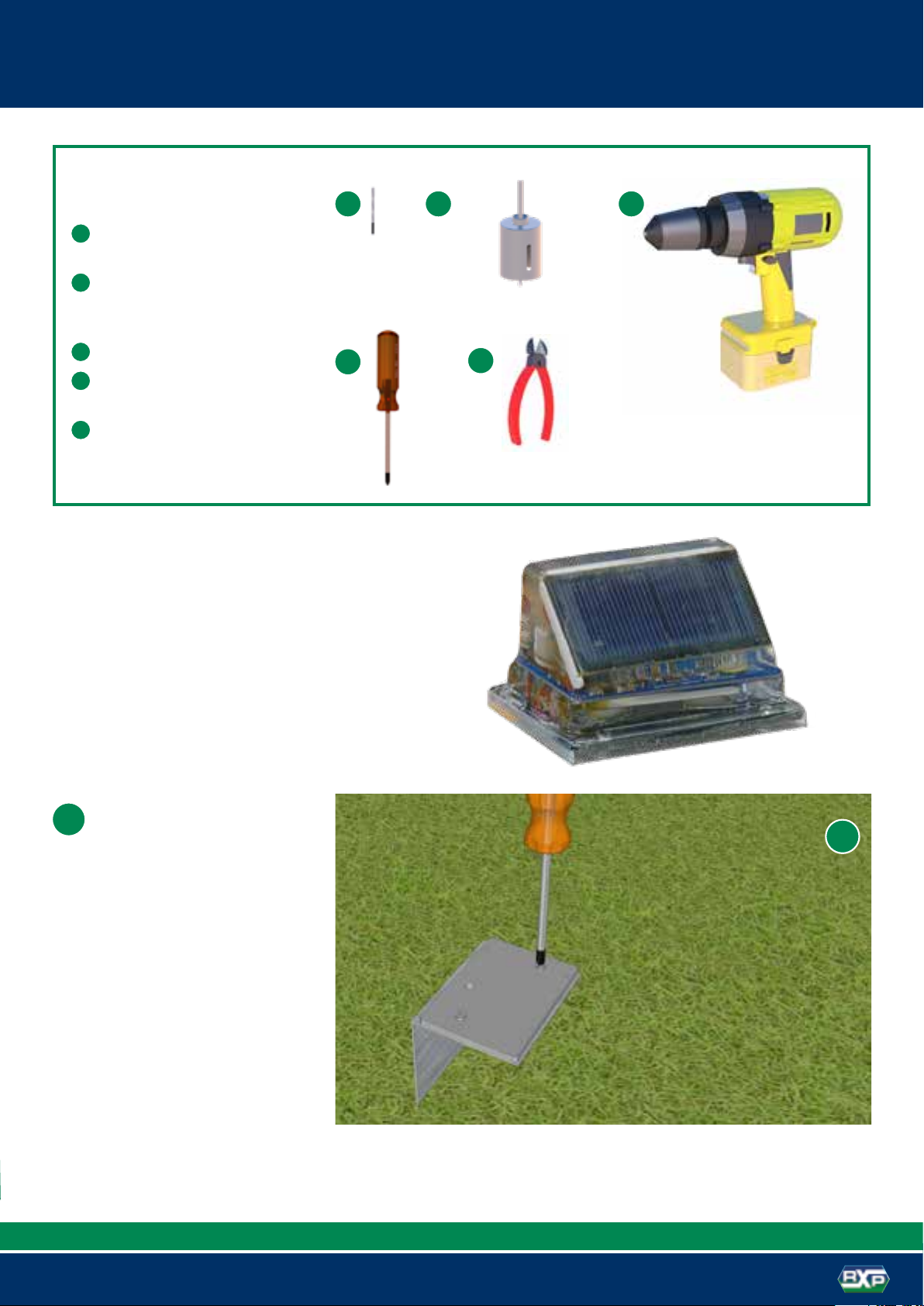
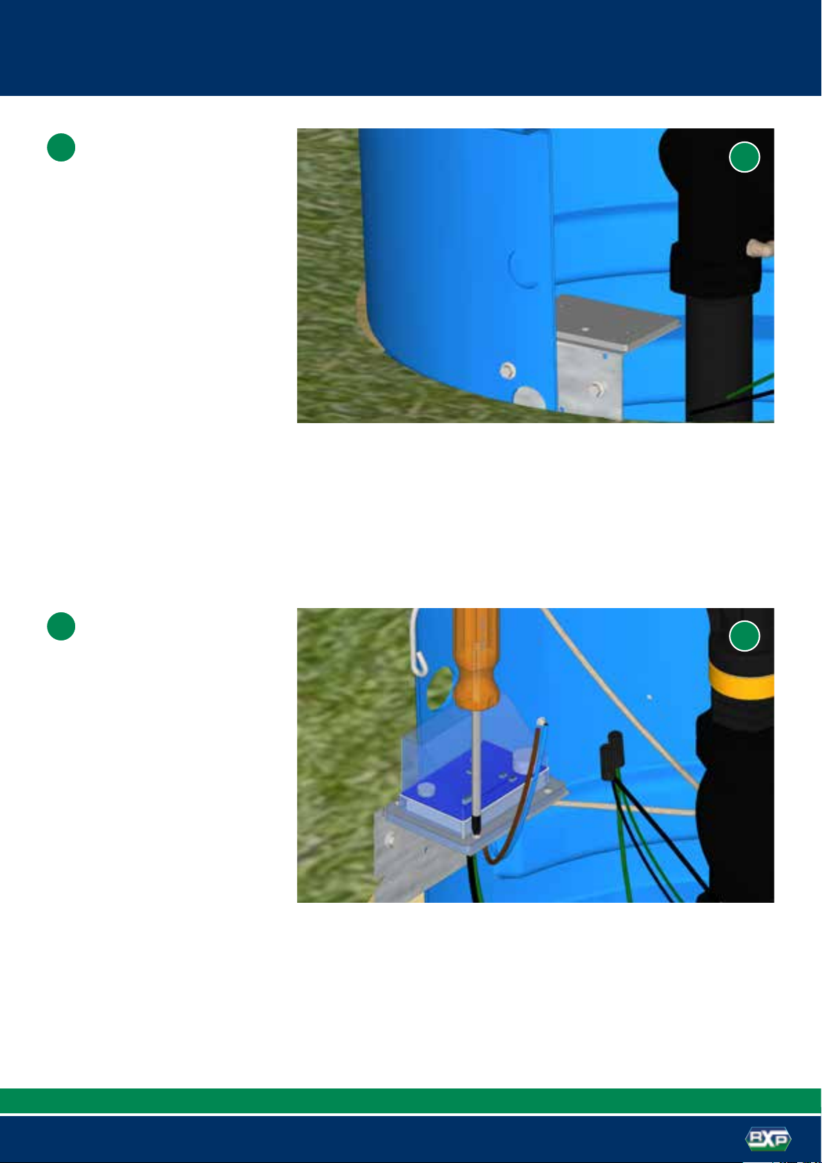
Battery Controller (C1013) 13 – 15
A guide to ensure you get the optimum
performance from your K-LineTM G-Set
C-1013 control.
KLGS.RX2000
KLGS.C1013
G-Set is an irrigation ‘system’, and to
achieve the desired outcome, must be
approached and treated as such, and
not an accumulation of components.
Contents
3
G-Set unit installation
The system comprises of a main-line telescoping through the
property, feeding 63mm MDPE ring-mains. This ring-main will have
the G-Set pods either directly attached to it, using tapping saddles, at
predetermined locations to suit the paddock layout and terrain (30m
to 40m spacing) or the tapping saddle attached to 63mm pipe and a
50mm feeder line to the G-Set in the side entry.
The ring-main of 63mm MDPE pipe needs to be installed below ground
to a depth of greater than 550mm (or less if side entry) particularly at
the points where the G-Set pod is to be located/installed. This pipe can
be trenched or mole ploughed. A combination of a GPS and survey and
visual assessment will be required to ensure correct placement of the
G-Set to achieve the desired coverage (DU).
At the desired location, dig
down and expose sufficient
pipe to allow for the fitting of
the 63mm tapping saddle.
1
1
Pipe Exposure and Saddle Install
G-Set install tools
A30mm hole saw – for the tapping saddle installation
B½"/13mm long socket 3/8" drive – for the tapping
saddle nuts
C
150mm socket bit 3/8" drive extension – for the
long socket
D
5/16 socket adaptor bit – for type17 tek screws
E3/8" drill adaptor
FDrill
Optional
G
Ratchet wrench – for tapping saddle nuts
F
A
C
E
D
B
G
Drill a 30mm hole
perpendicular to the lay of
the land. If side entry G-Set
is to be used, it should be
placed in the best direction
for the 50mm MDPE feed
pipe. It is important to ensure
this so that there is no undue
force on the tapping saddle
that can result in it being
difficult to achieve a
good long-term seal.
2
It is desirable to dig the hole required for the G-Set no bigger than necessary to allow
the installation and compaction of soil around the pod.The larger the hole, the harder
and more time consuming it is to get good compaction and secure placement.
2
4
G-Set unit standard installation
1
3
Fit the tapping saddle, complete with
male coupler and 32mm x 600mm
riser tube, securely to the pipe. Fill
and firmly compact the soil in the
hole to a height of 350mm from
finished ground level.
Lower the G-Set pod over the riser
tube, back fill and firmly compact
ensuring the rim of the pod is
parallel with the lay of the land. This
will result in the optimum sprinkler
coverage.
The unit is now ready for the valve/
sprinkler assembly to be fitted. This is
simply a matter of sliding this
pre-assembled unit onto the riser tube,
ensuring the bottom fitting’s sealing
o-ring is in the relaxed cavity, down
to the required height (top sprinkler
flush with the top of the pod). Hold the
green nut and rotate the assembly
until the bottom fitting is tight.
2
3
1
2
Attention needs to be given to ensure the 32mm riser
tube is not too long and going to foul the finger filter
in the valve. The riser tube will need to be shortened if
the 63mm pipe is mole ploughed to the minimum depth.
Outer
Cavity
Standard Installation
Inner
Cavity
5
G-Set unit side entry installation
Side Entry Installation
1
2
3
1
2
3
Having fitted the tapping saddle and
connector (50mm) onto the 63mm
Ring Main, dig a hole 350mm deep
and compact the hole suitable to
install the G-Set tightly into the hole.
Lower the G-Set pod into the
hole, firmly compacting the backfill
material as you go. Connect the
50mm feed pipe from the Ring
Main then continue to compact
and backfill to the soil surface.
The bottom, side G-Set holes,
should be at ground level.
The assembly should now be ready
to install the control system.
Ground
level
6
Completing the G-Set install
2Locate the second half of the
cover/sprinkler support and
screw into place ensuring the
base of the sprinkler is firmly
held around the orange slip
ring on the sprinkler. Three tek
screws are supplied to attach
each cover half.
Install the stock guard and the
unit is ready for commissioning
3
2
3
1Locate the first half of the
cover/support into the pod and
screw into place with the dish/
indent facing north or best
orientation to capture maximum
sunshine hours.
1
NOTE: Use a drill with a clutch to avoid the stripping of the
PE on the tek screw hole.
(Please Note: Control Systems need to be installed before this.)
7
Wireless controller (IPC)
1Place the IPC mounting block on
to the supplied bracket. Fix this
in place with the two supplied
self tapping screws in the
recessed holes.
1
KLGS.RX2000
A
DF
B C
Wireless controller
(IPC)install tools
A
4mm drill bit – for the zip clip for
the mount holes
B20mm hole saw – to drill the
aerial tube holes and access
holes
CDrill
D
Phillips head screwdriver – to
screw the IPC down
E
Side cutters – to cut wire ends
of solar and solenoid
*Indication of IPC only
8
Wireless controller (IPC) KLGS.RX2000
3The top three holes should be
drilled out with a 20mm hole
saw so as to view or access the
IPC from outside once the lid is
attached to the G-Set.
3
2Drill 4mm pilot holes into the
indicated holes (fig. 2) through
the bracket into the G-Set body.
The top of the bracket should
be placed approximately 50mm
below the lid attachment point
in the G-Set.
2
Drill 4mm
pilot holes
For IPC
connection
(See Fig 4)
50mm
Pilot
Holes
Pilot
Holes
Pilot
Holes Drill
out 20mm
9
KLGS.RX2000
Wireless controller (IPC)
5
Screw the mounting screws into
the IPC bracket from outside
using the holes identified in fig 2.
The bracket should be mounted
on the South side of the pod.
With the bracket attached, now
insert the IPC wires into the
10mm hole and using the four
supplied screws attach the IPC
to the PVC Base Plate.
44
5
10
Wireless controller (IPC)
7Drill an access hole through the
“tray” in the G-Set lid to allow
access of the solar panel wires
(blue and brown) and also the
aerial. The aerial will attach to
the solar panel plate.
The lid placement should be on
the South East or South West
part of the pod. This ensures
that the solar panel is facing
the North East or North West
direction. (The solar panel
would be obscured by the
sprinkler facing North).
KLGS.RX2000
7
6Connect the solenoid wires,
being careful to colour match
with the IPC wires.
Green = Green
Black = Black
Affix the wirenuts as specified in
fig. 10, taking carefull note of the
direction of the twist.
6
11
Wireless controller (IPC)
9
8
Screw the solar panel down
with a single tek screw into the
centre of the solar panel plate.
This plate fits neatly into the tray
stopping movement.
Draw the solar panel wires down
toward the IPC and attach the
aerial with the special clips.
KLGS.RX2000
8
9
Clips
Clips
12
Wireless controller (IPC) mounting instructions
This is how the IPC should be
finally mounted. The IPC should
now be programmed for final
use. This can be done before
the water system is functional
and will cause no damage to the
latch coil.
11
KLGS.RX2000
11
10 Connection of the solar panel
wires is simply connecting
brown IPC wire to brown solar
panel wire and the blue IPC to
the blue solar panel wire. This is
achieved by the use of the wire
nuts included.
10
Installing the Connectors
1. Strip wires ½"
2. Align frayed strands or conductors
3. Do not pre-twist. Place stripped wires together with ends
even, lead stranded wire slightly
4. Twist connector onto wires pushing firmly until hand-tight.
DO NOT over torque
5. Swipe excess sealant in and around conductors.
Do not reuse
13
Battery controller (C1013)
1
2
ABC
Connect the controller to the bracket.
Connect the bracket with two tek screws.
The cover should be placed before the
mounting of the tek screws holding the
lid to the G-Set.
Programming of the
controller should be
completed before mounting
KLGS.C1013
1
Battery controller (C1013)
install tools
APhillips head screwdriver
B
32mm hole saw – for the attachment of
the socket to the lid of the G-Set
CDrill
2
Cover
14
Battery controller (C1013)
4Screw two screws into the inserted base of the
solar panel. Screw a retaining tek screw into the
back from the top. Insert to left to fix rotation.
Double check at this point that the solar panel will
be facing the direction that captures maximum
sunshine hours.
The solar cable is then fed down through the
base to connect on to the controller. Plug the
cable from the solar panel to the cable from the
controller as shown.
Solar panel connector
5
KLGS.C1013
4
5
3Drill a 32mm hole to mount the solar panel ensuring
that it faces the best solar collection direction
generally this will be placed on the South East or
South West of the pod, with the panel facing West
of North or East of North.
3
Retaining
screw
placement
15
Battery controller (C1013)
6
7
Taking the included wire nuts,
you are then able to connect the
solenoid (latch) coil to
the controller.
Connect black latch wire to black
controller wire and the green
latch wire to the red controller
wire. This is achieved by the use
of the wire nuts included.
Red to green wire
Black to black wire
This is how the C1013 controller should be mounted.
Installing the Connectors
1. Strip wires ½"
2. Align frayed strands or conductors
3. Do not pre-twist. Place stripped
wires together with ends even,
lead stranded wire slightly
4. Twist connector onto wires
pushing firmly until hand-tight.
DO NOT over torque
5. Swipe excess sealant in and
around conductors.
Do not reuse
KLGS.C1013
6
RX PLASTICS LTD
PO Box 360 Ashburton
Phone +64 3 307 9081
Email [email protected]
www.rxplastics.co.nz
Agent:

Popular Irrigation System manuals by other brands

Tyco TFP PH5 Quick user quide

Tyco

Tyco TFP PH5 Quick user quide

dosatron D30 GL 02 owner's manual

dosatron

dosatron D30 GL 02 owner's manual

Viking VK2021 Technical data

Viking

Viking VK2021 Technical data

Irritrol SIS 120P Series Maintenance and operating instructions

Irritrol

Irritrol SIS 120P Series Maintenance and operating instructions

Rain S-Dial installation manual

Rain

Rain S-Dial installation manual

Gardena aquaBloom 13300 Operator's manual

Gardena

Gardena aquaBloom 13300 Operator's manual

Rain Bird 5000 Series installation instructions

Rain Bird

Rain Bird 5000 Series installation instructions

Tyco Rapidresponse LFII Series manual

Tyco

Tyco Rapidresponse LFII Series manual

Toro TS120 operating manual

Toro

Toro TS120 operating manual

Melnor 4501 User instructions

Melnor

Melnor 4501 User instructions

Reliable DH56 Dry quick start guide

Reliable

Reliable DH56 Dry quick start guide

Viking VK506 Technical data

Viking

Viking VK506 Technical data

Rain Bird 5000 Plus Series installation instructions

Rain Bird

Rain Bird 5000 Plus Series installation instructions

Blumat Classic Installation

Blumat

Blumat Classic Installation

Viking VK3021 Technical data

Viking

Viking VK3021 Technical data

Weathermatic PROLINE PL800 owner's manual

Weathermatic

Weathermatic PROLINE PL800 owner's manual

Kompernass KH 4083 operating instructions

Kompernass

Kompernass KH 4083 operating instructions

Underhill Tracker 2 T-400-2 Assembly and operating instructions

Underhill

Underhill Tracker 2 T-400-2 Assembly and operating instructions

manuals.online logo
manuals.online logoBrands
  • About & Mission
  • Contact us
  • Privacy Policy
  • Terms and Conditions

Copyright 2025 Manuals.Online. All Rights Reserved.