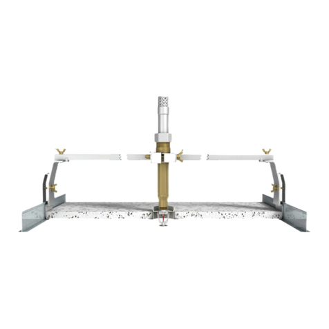
K. As depicted in Figure 3E, use the In-
stitutional Escutcheon Installation
Wrench to screw on the escutcheon
plate clockwise. The face of the es-
cutcheon plate is equipped with four
indentations to complement the de-
sign of the Institutional Escutcheon
Installation Wrench and facilitate in-
stallation of the escutcheon plate.
As the escutcheon plate is threaded
ontothesprinklerbody,thefourarms
of the lockring must fully engage with
theradialgroovesontheinsideofthe
escutcheon plate. Continue to thread
the escutcheon plate onto the sprin-
kler body until the plate’s flange fits
tightly againstthesurfaceoftheceil-
ing. Then, proceed to turn the es-
cutcheon plate another 1/2 turn
clockwise to ensure that it is secured
to the ceiling.
The arms of the lockring are angled
and designed to wedge into the
coined radial grooves on the inside
face of the escutcheon plate to keep
the escutcheon plate from being un-
screwed. Thus, anattempttoremove
theescutcheonplateafterinstallation
is prevented. DONOT MODIFY THE
UNIT.
L. The retaining flange, located behind
the finished ceiling, must fit snug
against the inner surface of the ceil-
ing to prevent vertical movement of
theassembly.Use a 1/8" hex wrench
to tighten the retaining flange screw
and secure the assembly into place
to prevent it from being pulled
through the ceiling.
M. DISASSEMBLY: Refer to section 9.
MAINTENANCE, paragraph D. and
follow all warnings and instructions.
9. MAINTENANCE
(Refer to Figures 1, 2, and 3.)
NOTICE: The owner is responsible for
maintaining the fire protection system
and devices in proper operating condi-
tion. For minimum maintenance and in-
spection requirements, refer to the ap-
propriate National Fire Protection Asso-
ciation’s pamphlet that describes care
and maintenance of sprinkler systems.
In addition, the Authority Having Juris-
diction may have additional mainte-
nance requirements that must be fol-
lowed.
A. The sprinklers must be inspected on
a regular basis for corrosion, me-
chanical damage, obstructions,
paint, etc. The frequency of the in-
spections may vary due to corrosive
atmospheres, water supplies, and
activity around the device.
B. Sprinklers that have been painted or
mechanically damaged must be re-
placed immediately. Sprinklers
showing signs of corrosion shall be
tested and/or replaced immediately
as required. Quick response sprin-
klers that are 20 years old shall be
tested and/or replaced as required.
Sprinklers that have operated cannot
be reassembled or reused, but must
be replaced. When replacing sprin-
klers, use only new sprinklers.
C. The sprinkler discharge pattern is
critical for proper fire protection.
Nothing should be hung from the
sprinkler, attached to it, or other-
wise obstruct the discharge pat-
tern. All obstructions must be imme-
diately removed or, if necessary, ad-
ditional sprinklers installed.
D. When replacing existing sprinklers,
the system must be removed from
service. Refer to the appropriate sys-
tem description and/or valve instruc-
tions. Prior to removing the system
from service, notify all Authorities
Having Jurisdiction. Consideration
should be given to employment of a
fire patrol in the affected area.
There are two methods of sprinkler
disassembly. In Method 1, the es-
cutcheon plate and lockring are re-
moved first, and then the remaining
sprinkler components can be re-
moved without being destroyed.
Note, however, that this first method
of disassembly results in damage to
the escutcheon plate and lockring,
and so they cannot be reused.
Using Disassembly Method 1:
1. Remove the system from service,
drain all water, and relieve all
pressure on the piping.
2. Use a 1/4" drill (not available from
Viking)to maketwoholesthrough
two opposite indentations on the
face of the escutcheon plate.
3.Useanadjustablespannerwrench
(not available from Viking) to un-
thread the escutcheon plate by
turning it counterclockwise. Make
sure that the sprinkler body does
not turn or loosen.
4. Remove the lockring from the
sprinkler body.
5. Place a protective sprinkler shell
(from the spare sprinkler cabinet)
over the sprinkler to be removed.
6. With the protective shell over the
sprinkler, place the special Flush/
Concealed Sprinkler Wrench over
the unit and turn it counterclock-
wise to carefully unthread the
sprinkler body from the reducing
coupling.
7. Installthe new unit using the Flush /
Concealed Sprinkler Wrench.
Caremustbe takentoensurethat
the replacement sprinkler is the
proper model and style, with the
appropriate orifice size, tempera-
ture rating, and response charac-
teristics. A fully stocked spare
sprinkler cabinet should be pro-
vided for this purpose. (Stock of
spare lockrings and escutcheon
plates should be available in the
spare sprinkler cabinet in addition
to the spare sprinkler heads.)
8. Place the system back in service
and secure all valves. Check the
replaced sprinklers and repair all
leaks.
Using Disassembly Method 2:
The second method of removing the
Model HQR-2 Institutional Quick Re-
sponse Flush Pendent Sprinkler re-
sults in complete destruction of the
unit. Therefore, none of the sprinkler
components may be reused:
1. Remove the system from service,
drain all water, and relieve all
pressure on the piping.
2. Disassemble and remove the fus-
ible element, andbend thedeflec-
tor and sealing assembly to ex-
pose the waterway of the sprin-
kler.
3. Insert an easy-out screw extractor
(Trade No. 6) into the waterway.
Turn the easy-out counterclock-
wise with a wrench to remove the
sprinkler assembly from the re-
ducing coupling.
5. Install the new unit usingtheFlush/
ConcealedSprinklerWrench.Care
must be taken to ensure that the
replacement sprinkler is the
proper model and style, with the
appropriate orifice size, tempera-
ture rating, and response charac-
teristics. A fully stocked spare
sprinkler cabinet should be pro-
vided for this purpose. (Stock of
spare lockrings and escutcheon
plates should be available in the
spare sprinkler cabinet in addition
to the spare sprinkler heads.)
6. Place the system back in service
and secure all valves. Check the
replaced sprinklers and repair all
leaks.
E. Sprinkler systems that have been
subject to a fire must be returned to
service as soon as possible. The en-
tire system must be inspected for
damage and repaired or replaced as
necessary.Sprinklersthathavebeen
exposed to corrosive products of
combustionorhighambienttempera-
tures, but have not operated, should
be replaced. Refer to the Authority
Having Jurisdiction for minimum re-
placement requirements.
TECHNICAL DATA
March 18, 1999
Sprinkler 60 d
MODEL HQR-2 INSTITUTIONAL
QUICK RESPONSE FLUSH
PENDENT SPRINKLER
Form No. F_100998
Replaces page 60 a-d, dated February 25, 1999
(added disclaimer and installation tip).
