ALIBI ALI-NS2114L User manual

1www.observint.com
ALI-NS2114L 4MP White Light IP Turret Camera Quick Installation Guide
ALI-NS2114L_CQ
190603
What’s in the box
Your camera includes the items shown below:
• Security L-wrench
• Mounting hardware - four screws and
wall inserts
• Drill template
• Waterproof Ethernet Fitting
• Installation and setup instructions
Step 1. Route wiring to the camera
Interface cables can be routed into the camera either through the adapter plate (through the mounting
surface) or through the cable channel on the side of the camera.
NOTE
When selecting a mounting location for the camera
• Make sure that there are no reective surfaces near to the camera lens. Light from the camera may
bounce back onto the lens causing reections.
• Determine how interface wiring are routed into the camera. The cable can be routed through the
mounting surface and access hole in the mounting plate or through the side inlet.
The camera includes connectors for the following:
• Ethernet (required): The Ethernet drop cable can connect to a LAN extension cable from a
switch or Network Video Recorder. The camera can be powered across the LAN using power over
Ethernet (PoE) injection. See the Specications section at the end of this document for power
requirements. A weatherproof Ethernet Fitting is provided.
• 12 Vdc power input (optional if PoE powered, required if not): If powering the camera
with a long power extension cable, refer to the tables at the end of this guide for wire gauge
requirements. Voltage input at the camera can be within the range 12 Vdc ± 25%.
1. Route a LAN extension cable from a network switch or Network Video Recorder to where the
camera will be installed.
2. If the camera is not powered using PoE, route 12 Vdc power cables from an adequate power
source to the location where the camera will be installed. Voltage input at the camera can be
within the range 12 Vdc ± 25%.
Step 2. Remove the Adapter plate
To remove the adapter plate:
1. Set the camera base down on a clean surface.
Trim ring
2. Rotate the trim ring counter-clockwise as shown in the picture above (about 30°), and then lift it
o of the camera assembly.
Fixing screw (loosened)
and tab Lip
Adapter plate
Shroud and turret assembly
3. Using the security L-wrench, fully loosen the xing screw (captive screw). See photo above.
This document guides you through the basic steps to install and congure the ALI-NS2114L network
turret camera. This camera features:
• 1/1.8” 2688 × 1520 pixel (4 MP) Progressive Scan CMOS @ 30 fps
• 3000°K soft white light LED with 100 ft range (see Step 10 in the procedure below)
• 4 mm lens with 94° FOV
• 120 dB Wide Dynamic Range
• Built-in Microphone
• Built-in microSD/SDHC/SDXC slot, up to 128GB
• H.265, H.265+, H.264+, H.264 video compression
• IP66, IK10 vandal proof rated
• Optional ALI-AB1 Alibi short wall mount bracket, ALI-AB2 Alibi long wall mount bracket,
ALI-AA1, ALI-AA2 brackets, ALI-AJ1 ange adapter
For more information, refer to these documents - available from your equipment vendor:
• ALIBI™ Witness 2.0 r3 App for Android or iOS Quick Start Guide
• ALIBI™ IP Camera Firmware Version 5.4 User Manual (or later) provided at:
AlibiSecurity.com/resources
Trim ring
Lens
Shroud
and turret
assembly
Built-in
microphone
Turret “UP”
orientation
Maintenance
panel with
microSD slot
and Reset*
Adapter plate Cable channel Drop cable
White light LEDs
Camera assembly
Fixing screw
and tab
Cable channel
plug
Tabs to hold
turret assembly
Cable channel
Holes for surface
mounting screws (3)
Holes for bracket
mounting screws
Adapter plate
Ethernet RJ-45 (with PoE)
12 Vdc connector
Drop cable connectors

2www.observint.com
4. Slide the tab away from the lip on the bottom of the shroud and turret assembly, and then
separate the shroud and turret assembly from the adapter plate.
Step 3. Install a microSD card (optional)
Install a microSD card in the camera to save alarm and status information locally, and to locally save
video and captures les. Refer to the Specications section for storage card requirements. The storage
card can be a
microSD/SDHC/SDXC card, up to 128GB. NOTE: The card can be formatted within the
camera, if necessary.
To install the card:
1. Rotate the turret within the shroud and turret assembly to gain access to the maintenance panel
cover.
2. Remove the panel cover using the security L-Wrench provided.
Reset* button
microSD card slot
3. Push the microSD card into the slot until it is fully seated, and then release it. When installed
properly, it will slide into the slot smoothly, and be held in place after release.
4. Reinstall the maintenance panel cover.
NOTE
* RESET: To restore the camera to its default settings, hold down the RESET button for about 10
seconds when the camera is powering on or rebooting. Reset will deactivate the camera and restore
the default IP address, port number, conguration settings, etc.
5. Install the camera
Install the adapter plate
The camera can be mounted onto a wall or ceiling, or onto one of the brackets list above in the
introduction.
The mounting surface should support at least four (4) times the weight of the
camera.
1. To attach the adapter plate using a
ALI-AB1, ALI-AB2, ALI-AA1, ALI-AJ1 or ALI-AA2
bracket:
a. Install the bracket
b. Attach the adapter plate to the bracket using the screws provided.
2. To attach the adapter plate to a mounting surface:
a. Use the drill template or the adapter plate, mark the location of the holes for the mounting
screws. Use the three holes marked “1” for mounting screws to attach the camera to a
surface. If routing the cables into the camera through the mounting surface, mark the
location of the opening in the adapter plate for the cables.
b. Drill holes in the mounting surface where needed for the fasteners and cable routing.
c. Attach the adapter plate to the mounting surface using three screws.
Tabs to hold turret assembly
Fixing screw
and tab
Mounting surface
Connect the interface cables
3. Connect the network LAN and power extension cables to the camera drop cables:
a. Connect the Ethernet LAN cable to the camera LAN drop cable. Protect the connection
from moisture and other contamination, if necessary. A Weatherproof Ethernet Fitting is
provided. Installation instructions for the tting are included later in this document.
Network drop cable
from camera Network cable from
router or switch
Weatherproof Ethernet Fitting installed
WARNING
!
Failure of the power or Ethernet connector due to moisture or another
contaminant is considered an installation error, which voids the warranty. If
installing this camera in a location such as an overhang, shop, garage, kitchen,
etc. where high humidity or dust is present, seal these connections adequately.
b. If the camera is not powered using PoE (Power over Ethernet injector), connect the 12 Vdc
power cable to the camera drop cable. The polarity of the drop cable connector is shown
in the drop cable photo above.
CAUTION
Do not apply power to the camera at this time. Before applying power to the camera, ensure
that the polarity is correct. An incorrect connection may cause a malfunction and can damage
the camera.
4. For outdoor installations, seal holes drilled in the mounting surface to block moisture and other
contaminants, if necessary.
5. Reattach the camera to the adapter plate. Note that the lip on the turret and shroud assembly is
held in place by the two tabs on the adapter plate (see photo above), and the tab (with the xing
screw) is slid inwards over the lip to secure the camera to the plate. Tighten the xing screw
enough to so the tab doesn’t slip o the lip.
6. Adjust the turret and shroud assembly so that the “UP” mark on the turret is up.
WARNING
!When applying power to the camera, the LED lamp will switch on for about 5 seconds.
It is very bright.
Avoid looking at the camera when applying power.
7. Apply power to the camera through the 12 Vdc power cable or PoE injector, as congured.
Step 4. Install the Alibi Config Tool software
NOTE: If the camera LAN extension cable is attached to a Network Video Recorder (NVR), skip this step.
The Alibi Cong Tool is a PC-based network utility for discovery of Alibi compatible devices. It provides
an easy way to activate devices, congure camera and recorder network conguration settings, and set
device passwords. It can be installed on a Microsoft® Windows® operating system that has direct access
to the network where your Alibi devices are installed. You can download the Alibi Conguration Tool
from Supercircuits.com or AlibiSecurity.com/Resources.
1. Download the Alibi Cong Tool from the Supercircuits.com or AlibiSecurity.com/Resources
website. At the time when this document was published, the le is named: alibi-cong-tool.
zip and is about 80MB.
2. Un-zip the le on a computer with Microsoft Windows (Windows 7 or newer) that is connected
to the LAN where your Alibi camera is connected.
3. Run the le contained in the zip le: Alibi Cong Tool.exe. Follow the on-screen instructions
to install the le.
4. Open the Alibi Cong Tool application. When the application opens, it automatically “discovers”
and lists all Alibi compatible devices on the LAN. See below.
© 2019 Observint Technologies. All rights reserved.

3www.observint.com © 2019 Observint Technologies. All rights reserved.
Note: In the screen above, the tool can discover devices on other subnets. It will also list other
Alibi compatible devices on the LAN, and devices with the address 192.168.1.64 (an inactive Alibi
device).
Step 5. Activate Inactive Alibi device
NOTE: If the camera LAN extension cable is attached to a Network Video Recorder (NVR), skip this step.
Refer to the documentation available for your NVR rmware for the procedure to activate the camera, if
necessary.
When an Alibi device is rst installed, or reset to its factory conguration, it must be “Activated” before
it can be used. In the Alibi Conguration Tool, “Inactive” devices have a Security status of Inactive,
and an IPv4 address of 192.168.1.64. A device is “Activated” when a password is assigned to the
admin username of the device.
In the example below, an ALI-NS2114L camera is activated and congured for its network. The
procedure is similar for all other Alibi network cameras currently available.
1. Scan through the list of devices the Alibi Cong Tool discovered for the Inactive device you want
to activate (see below). Click on the device in the list to highlight it, and then click the select box
to check it. See below.
ActivateSelected
2. Click the Activate button. In the Activate window, you will create a password for the admin
(administrator) username.
a. In the Activate window, enter an a password for admin in the New Password eld.
Include a combination of uppercase, lowercase alphabetic characters and numbers to
create a “Strong” password. The rating is shown beneath the Password eld. See above.
b. Enter the admin password again in the Conrm eld, and then click Activate. In the
screen below, notice that the device Security status shows “Active”. Record your admin
password for reference later.
CAUTION
If you lose your admin (administrator) password, you cannot congure the device or restore
it to its factory settings. To reset your password, call your support organization for specic
instructions.
Notice that although the device is now activated, it retained the default IP address.
Step 6. Edit Network Parameters
NOTE: If the camera LAN extension cable is attached to a Network Video Recorder (NVR), skip this
step. The camera will receive network conguration settings from the NVR. Refer to the documentation
available for your NVR rmware for more information.
You can change the network parameters of devices that are active.
1. In the list of devices discovered, click on the device you want to change the network settings for,
and then click the select box to check it. See below.
Edit Network Parameters
2. In the popup window, edit the current network parameters, and then enter the Administrator
(admin) user password in the eld at the bottom.
a. Enable DHCP: You can select Enable DHCP to acquire compatible network settings
from a DHCP server installed on the LAN. However, these settings might be changed later
by the DHCP server. Since it is recommended to use an unchanging IP address, you can use
DHCP to acquire compatible network settings, and then uncheck Enable DHCP and save
that conguration to retain the new network parameters.
b. In the example below, Enable DHCP was checked to acquire compatible network
settings from the DHCP server.
3. Click OK to save your settings. The parameter change(s) will be shown device’s network
parameters (see below).
Step 7. Login to the camera
NOTE: If the camera LAN extension cable is attached to a Network Video Recorder (NVR), skip this step.
Microsoft® IE is used to access your camera remotely. IE must run as an Administrator to use all features
available through a remote login to the camera.
Setting MS Internet Explorer to run as an Administrator
Window 7: To run IE as an Administrator:
1. Find or create an IE icon on your computer desktop.
2. Hold down the shift key, and then right-click on the IE icon.

4www.observint.com © 2019 Observint Technologies. All rights reserved.
MS Internet
Explorer icon
Run as administrator
3. Click Run as administrator in the pop-up menu.
Window 10:
To run IE as an Administrator:
1. Find MS IE in the start menu. Usually this is found in the Windows Accessories group.
2. Pin the entry to Start.
3. Right click on the Internet Explorer tile, and then select More | Run as administrator.
Run as
administrator
To login to the camera from a computer on the same LAN:
1. Open your Microsoft Internet Explorer (IE) browser on your computer and enter the IP address of
the camera in the URL eld. In the example below, the IP address of the camera is 192.168.0.7.
2. In the login window, enter admin for the User Name and the password you created in the
Password eld, the click Login.
3. If this is the rst time you are logging into a camera, you may see the message in the following
screen. If this appears, follow the sub-steps below.
a. Click on the message to install the plugin.
b. In the message bar at the bottom of the screen, click Run. Follow the on-screen
instructions to install WebComponents. When the following screen opens, click Finish.
The Live View screen with the camera video image should appear.
Capture, Record, Zoom icons
Screen select tabs Logout buttonLive View image
Step 8. Adjust camera pan, tilt and rotation
Adjust the camera pan, tilt and rotation to point the camera at your surveillance target. When pointing
the camera, use the Live View display on a recorder or remote login.
1. To aim the camera at your surveillance target:
a. Adjust the pan: grasp the turret and shroud assembly on the sides of the camera and turn.
Tilt range:
0˚ ~ 75˚
Rotation range:
0˚ ~ 360˚
Pan range:
0˚ ~ 360˚

5www.observint.com © 2019 Observint Technologies. All rights reserved.
b. Adjust the tilt: grasp the turret and tilt as needed for the image height.
c. Adjust the rotation: grasp the turret and turn as needed to adjust the horizontal in the
image.
2. Tighten the xing screw to hold the turret in place.
3. Reinstall the trim ring.
Step 9. Adjust the camera image for your surveillance target
Use the rmware menus to adjust the brightness, contrast, saturation and sharpness of the video image
if necessary. These settings are initially optimized at the factory and may not need adjustment. When
adjustments are necessary, the paths to the image settings menus are dierent if the camera is installed
as a device on a LAN, or if it is connected to a NVR. Select the installation type below for your camera to
complete this step.
For cameras installed on a LAN
1. If necessary, log into the camera on the LAN with administrative credentials.
2. After adjusting the camera for the a typical eld of view, click the Setup tab, and then click the
Image link in the left frame.
3. Adjust the Brightness Contrast, Saturation and Sharpness of the image. Each parameter can be
set to a level of 0 ~ 100 either by moving the slider or entering the value in the box on the right.
The eect of the adjustment will appear in the Live View image in the menu.
Refer to the rmware user manual for your camera to use the other submenus on this screen.
For cameras connected directly to an NVR
1. Log into the NVR with administrative privileges.
2. Open the rmware Image menu. Go to Menu | Camera Management | Image
3. In the Camera eld drop down list, select the camera you want to congure. In the example
above, [D1]IPCamera 01 is selected.
4. Drag the Brightness, Contrast, Saturation and Hue adjustment markers left or right to
perfect the image from the camera. For some adjustments, you can click the up ( 5)or down
( 6)icons near the adjustment value (on the right side) to incrementally change the value of
those adjustment.
5. Click Apply to save your settings for this camera.
Refer to the rmware user manual for your NVR to use the other submenus on this screen.
NOTE
Cleaning: If cleaning is necessary, use clean cloth with a few drops of ethanol and wipe it gently.
Step 10. Configure the White Lite LED
You can manage the behavior of the camera’s White Lite LED through the camera’s internet interface.
1. Log into the camera using IE. The URL for logging into the camera depends on whether the
camera is attached directly to a network (switch), or is attached to the internal switch of an NVR:
—If the camera is connected to a switch on the LAN: You can log directly into
the camera with a PC attached to the same network using Internet Explorer and the IP
address of the camera as the URL. See “Step 7. Login to the camera” on page 3.
Use credentials for the camera that have administrative privileges
—If the camera is connected to the NVR internal switch:
i. Determine which Ethernet port (channel) on the NVR that camera is connected to.
ii. Log into the NVR with a PC on the same network as the NVR. Use Internet Explorer,
the IP address of the NVR as the URL, and use credentials for the NVR that have
administrative privileges.
iii. Open the display on the NVR to show the links for the cameras attached to the
NVR. Go to the display Conguration | Camera Management | IP Camera
iv. For the channel the camera is attached to (in this example, Channel 3, see above),
click on the link in the Connect column on the far right. A new browser tab will
open showing the login screen for the camera.
v. Log into the camera with using credentials for the camera that have administrative
privileges.
2. Open the External Device conguration menu. Go to:
Conguration | System | System Settings | External Device
a. Check the Enable Supplement Light select box.
b. On the LED Brightness Adjustment line, select either Manual (to manually select the
level with the slider [see above]) or Auto (brightness is set automatically).

6www.observint.com © 2019 Observint Technologies. All rights reserved.
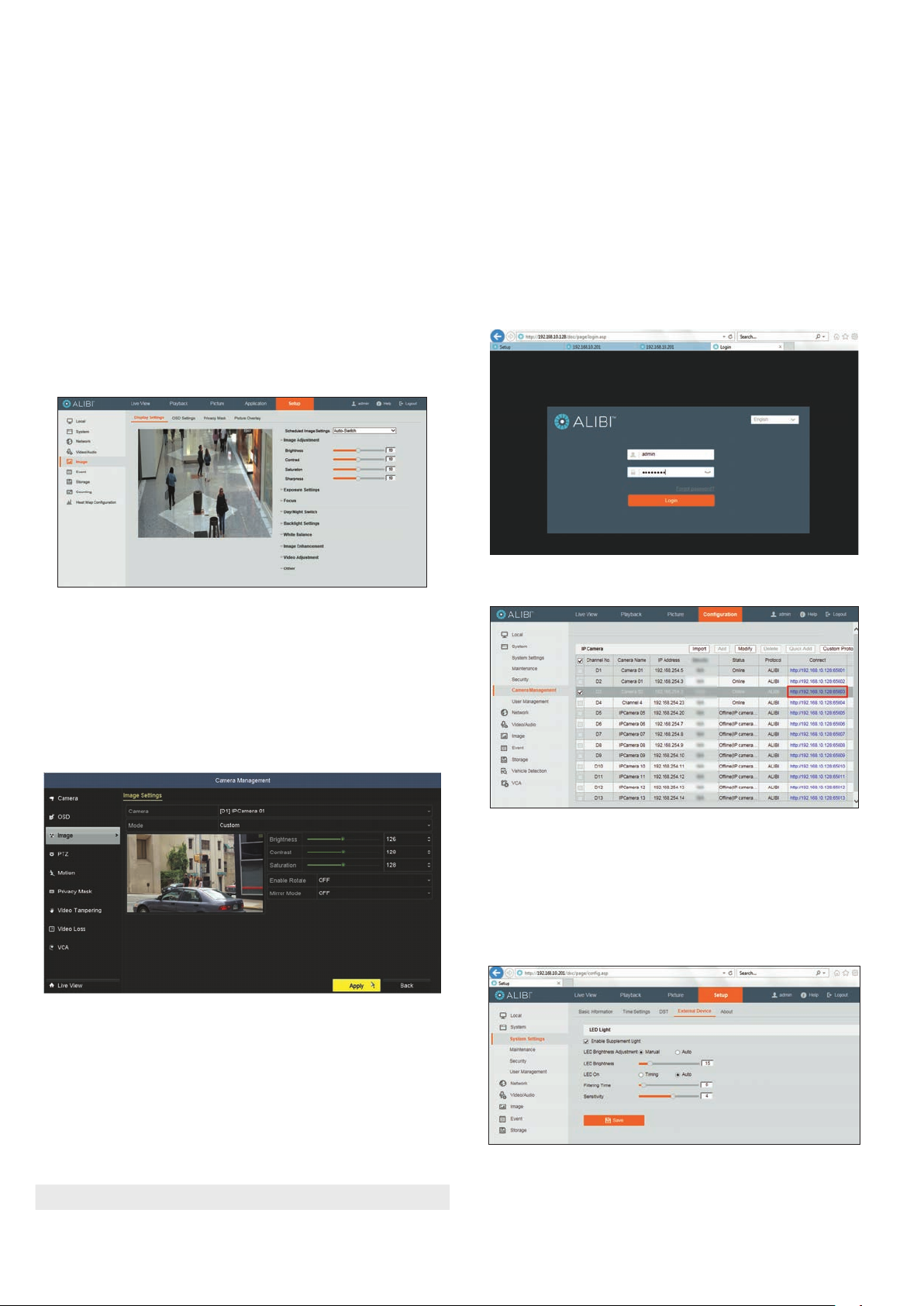
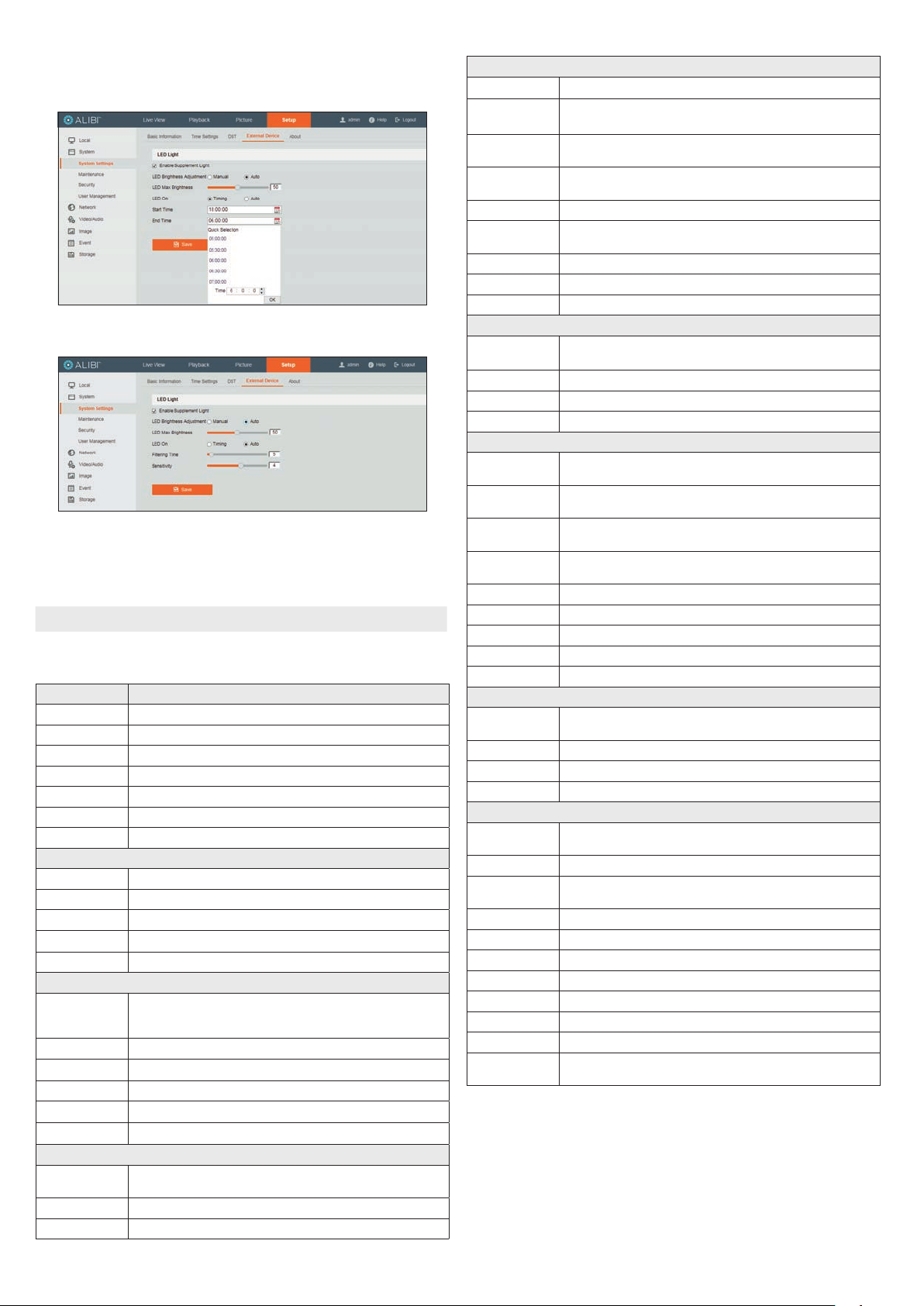
c. On the LED On line, select either Timing or Auto.
Timing: With this option (see below), you can select the time range when the LED light
will be used.
Auto: With this option (see below), the LED is enabled based on the darkness of the
environment. You can set two options: Filtering Time and Sensitivity.
Filtering Time (5 .. 120 seconds) refers to the interval time between the day/night
switch.
Sensitivity: (0 .. 7) The higher the value is, the easier the mode switches.
3. Click Save to retain your settings.
NOTE Perfecting the LED Light settings for your camera and environment may require some re-adjustment.
Specications
Camera ALI-NS2114L
Image Sensor 1/1.8” Progressive Scan CMOS
Min. Illumination 0.0014 Lux @ (F1.0, AGC ON), 0 Lux with light
Shutter speed 1/3 second to 1/100,000 second
Slow shutter Supported
Digital noise reduction 3D DNR
Wide Dynamic Range 120 dB
Adjustment Range Pan: 0° ~ 360°, tilt: 0° ~ 75°, rotate: 0° ~ 360°
Lens
Focal length 4 mm
Aperture F1.0
Focus Fixed
Field of View (FOV) 4 mm, horizontal FOV: 94°, Vertical FOV: 48°, diagonal FOV: 115°
Lens Mount M14
Compression Standard
Video compression
Main stream: H.265 / H.264
Sub stream: H.265 / H.264 / MJPEG
Third stream: H.265 / H.264
H.264 Type Main Prole / High Prole
H.264+ Type Main stream supported
H.265 Type Main Prole
H.265+ Type Main stream supported
Video bit rate 32 kbps to 16 kbps
Smart features
Behavior Analysis Line crossing detection, Intrusion detection, Unattended baggage detection,
Object removal detection
Exception detection Scene change detection
Face Detection Yes
Image
Max. Image Resolution 2688 × 1520 pixels
Frame Rate 50 Hz: 25 fps (2688 × 1520, 2560 × 1440, 2304 × 1296, 1920 × 1080, 1280 × 720)
60 Hz: 30 fps (2688 × 1520, 2560 × 1440, 2304 × 1296, 1920 × 1080, 1280 × 720)
Sub Stream 50 Hz: 25 fps (640 × 480, 640 × 360, 320 × 240)
60 Hz: 30 fps (640 × 480, 640 × 360, 320 × 240)
Third Stream 50 Hz: 25 fps (1280 × 720, 640 × 360, 352 × 288)
60 Hz: 30 fp s(1280 × 720, 640 × 360, 352 × 240)
Image Enhancement BLC/3D, DNR/HLC
Image Settings Rotate mode, saturation, brightness, contrast, sharpness, AGC, white balance adjustable by client
software or web browser
Day/Night Switch Day / Night
ROI Supports 1 xed region for main stream and sub stream separately
Day/Night Switch Auto / Schedule / Triggered by Alarm In
Audio
Environmental noise
ltering Yes
Sampling rate 8k Hz / 16 kHz / 32 kHz / 44.1 kHz / 48 kHz
Audio compression G.711 / G.722.1 / G.726 / MP2L2 / PCM
Audio bit rate 64 Kbps (G.711) / 16 Kbps (G.722.1) / 16 Kbps (G.726) / 32 - 160 Kbps (MP2L2)
Network
Network Storage Built-in microSD / SDHC / SDXC card slot (up to 128 GB) local storage and NAS (NFS, SMB/CIFS),
ANR
Alarm Trigger Motion detection, video tampering alarm, HDD full, HDD error, network disconnected,
IP address conicted, illegal login
Protocols TCP/IP, ICMP, HTTP, HTTPS, FTP, DHCP, DNS, DDNS, RTP, RTSP, RTCP, PPPoE, NTP, UPnP, SMTP, SNMP,
IGMP, 802.1X, QoS, IPv6, Bonjour
General Function One-key reset, Anti-Flicker, three streams, heartbeat, mirror, password protection, privacy mask,
watermark, IP address ltering
System Compatibility ONVIF (Prole S, Prole G), ISAPI
Simultaneous live view Up to 6 channels
User / Host Up to 32 users, 3 levels: Administrator, Operator and User
VMS Alibi CMS (ACMS), ACMS XP
Web browser Microsoft Internet Explorer 8 or later
Interface
Communication
Interface 1 RJ45 10M / 100M self-adaptive Ethernet port
On-board Storage Built-in micro SD/SDHC/SDXC slot, up to 128 GB
Audio 1 audio input (built-in mic ), mono sound
Reset Button Yes
General
Operating Conditions -22 °F ~ 140 °F (-30 °C ~ 60 °C)
Humidity 95% or less (non-condensing)
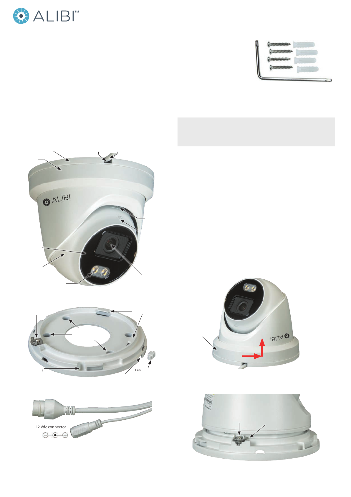
Power Supply 12 Vdc ± 25%, PoE (802.3af Class3), 5.5 mm coaxial power plug
Power Consumption 12 Vdc, 0.5 A, max. 6 W
PoE (802.3at, 36V ~ 57V), 0.3 A ~ 0.1 A, max. 7.5 W
Visible light temperature 3000°K soft white light
Visible light range Up to 100 ft (30 m)
Impact protection IK10
Weather Proof IP66
Material Camera: metal, trim ring: plastic
Dimensions Φ 5.4” × 4.9” (Φ 138.3 mm × 125.2 mm)
Weight Camera: 1.3 lb (575 g); with package, 1.8 lb (833 g)
Options ALI-AB1 Alibi short wall mount bracket, ALI-AB2 Alibi long wall mount bracket,
ALI-AA1, ALI-AA2 brackets, ALI-AJ1 ange adapter
Using the Waterproof Ethernet Fitting
Install the Waterproof Ethernet Fitting on the Ethernet cable end at the camera when moisture
or contamination exists in the area near the camera. The tting includes several parts that must be
installed in a specic order. To install the tting:

7www.observint.com © 2019 Observint Technologies. All rights reserved.
1. Place the rubber O-ring over the camera drop cable end cap.
Push the O-ring up to the connector cap.
2. Place the Lock Nut onto the network cable from the router
or switch as shown in the drawing to the right. The inside
threads must be toward the camera end.
3. Place the rubber basket onto the network cable above the lock
nut as shown.
4. Place the end cap onto the network cable above the rubber
gasket as shown. The ngered end must be toward the router
or switch.
5. Install an RJ-45 connector onto the network cable.
6. Plug the RJ-45 connector with the network cable into the
camera network drop cable.
7. Fit the end cap on the network cable onto the camera drop
cable end cap. Rotate the network cable end cap to lock it in
place.
8. Push the rubber gasket fully into the end of the network cable
end cap.
9. Screw the lock nut onto the network cable end cap until it is
fully seated.
Network drop cable
from camera
Network cable from
router or switchEthernet Fitting installed
Ethernet Fitting assembled and connected
Drop cable
end cap
Network drop
cable from
camera
Rubber
O-ring
seal
RJ-45
connector
End cap
Rubber
gasket
Network
cable
from
router or
switch
Lock nut
Table of contents
Other ALIBI Security Camera manuals

ALIBI
ALIBI ALI-TP7112RH User manual

ALIBI
ALIBI ALI-TS1025R User manual

ALIBI
ALIBI ALI-PTZ30XR User manual

ALIBI
ALIBI ALI-TS3012R User manual

ALIBI
ALIBI ALI-NS1034R User manual

ALIBI
ALIBI ALI-NS2122VR User manual

ALIBI
ALIBI ALI-TS1125R User manual

ALIBI
ALIBI ALI-NS2004R User manual

ALIBI
ALIBI ALI-NS3012R User manual

ALIBI
ALIBI ALI-TS2118VR User manual

ALIBI
ALIBI ALI-TP3005L User manual

ALIBI
ALIBI ALI-CD1080PVF User manual

ALIBI
ALIBI ALI-IPV30 User manual

ALIBI
ALIBI ALI-NS4004R User manual

ALIBI
ALIBI ALI-NS2012R User manual

ALIBI
ALIBI ALI-TS3015R User manual

ALIBI
ALIBI ALI-NS2036VR User manual

ALIBI
ALIBI ALI-NS1102VR User manual

ALIBI
ALIBI ALI-NS2018VR User manual

ALIBI
ALIBI ALI-NS7112R User manual