Alimak Tractel Tracpode PRO Installation guide

EN
FR
DE
NL
ES
IT
PT
GR
NO
SE
FI
DK
PL
PART OF ALIMAK GROUP
© COPYRIGHT – ALL RIGHTS RESERVED – www.tractel.com
fig. 0
Installation, operating and maintenance manual English Original manual EN
Manuel d'installation d'emploi et d'entretien Français Traduction de la notice originale FR
Installations-, Gebrauchs- und
Wartungsanleitung Deutsch Übersetzung der Originalanleitung DE
Handleiding voor installatie, gebruik en
onderhoud Nederlands Vertaling van de oorspronkelijke handleiding NL
Manual de instalación, de utilización y de
mantenimiento Español Traducción del manual original ES
Manuale dʼinstallazione, dʼimpiego e di
manutenzione Italiano Traduzione del manuale originale IT
Manual de instalação, de uso e de manutenção Português Tradução do manual original PT
Εγχειρίδιο εγκατάστασης, χρήσης και
συντήρησης Ελληνικά Μετάφραση του πρωτότυπου εγχειριδίου GR
Installasjons-, bruks- og vedlikeholdshåndbok Norsk Oversettelse av originalanvisning NO
Installations-, bruks- och underhållsanvisning
Svenska Översättning av originalbruksanvisningen SE
Asennus-, käyttö- ja huoltokäsikirja Suomi Alkuperäisen ohjeen käännös FI
Manual for installation, brug og vedligeholdelse Dansk Oversættelse af den originale manuall DK
Instrukcja instalacji, użytkowania i konserwacji Polski Tłumaczenie oryginalnejinstrukcji obsługi PL
Mobile anchor point
Point d'ancrage mobile
Beweglicher Anschlagpunkt
Mobiel verankeringspunt
Punto de anclaje móvil
Punto di ancoraggio mobile
Ponto de amarração móvel
Κινητό σημείο αγκύρωσης
Mobilt forankringspunkt
Mobil förankringspunkt
Siirrettävä kiinnityspiste
Bevægeligt forankringspunkt
Ruchomy punkt zamocowania
Tracpode PRO – EN 795-B/2012

1
2

fig. 2
2.2
c
1
2.1
2.3
e
b
a
1
2
CLACK!
d
2
3

a
c
b
fig. 3
a1
fig. 4
b2
b1
a2
2
1
3
3
2
1
4
3
4

fig. 5
a
2
1
3
1
2
d
b
c
5
5

TRACTEL S.A.S.
RD619 Saint-Hilaire-sous-Romilly
B.P. 38 - F-10102 FRANCE
2006/42/CE
CaRol R TS
Blocfor R
Blocfor R
250925.ind-00.10-23
Etiquette Tracpode Pro
250925.ind-00.10-23
362 x 52 mm
Dessins et textes noir
Fond blanc
250 kg
150 kg
150 kg
150 kg
EN 795 B
TS 16415
150 kg 150 kg
h
NO
Blocfor R
EN 360
EN 1496 B
CaRol R TS
EN 1496 A
CaRol R TS
2006/42/CE
CaRol R Pro
2006/42/CE
CaRol R Pro
CaRol R Pro
EN 1496 A
330 lbs
/ 150 kg
330 lbs
/ 150 kg
330 lbs
/ 150 kg
330 lbs
/ 150 kg
+
330 lbs
/ 150 kg
330 lbs
/ 150 kg
330 lbs
/ 150 kg
CaRol R TS
CaRol R Pro
330 lbs
/ 150 kg
150 kg
Stopfor
150 kg
330 lbs
/ 150 kg
330 lbs
/ 150 kg
EN 353.2
Blocfor
330 lbs
/ 150 kg
550 lbs
/ 250 kg
550 lbs
/ 250 kg
6
6

H01 = 1,62 m
H1 = 1,51 m
51 mm
fig. 7
DE1 =
1,31 m
HO2 = 1,57 m
H2 = 1,46 m
51 mm
DE2 =
1,27 m
HO3 = 1,52 m
H3 = 1,41 m
51 mm
DE3 =
1,23 m
1,12 m
DE1 =
0,06 m
7
7

8
EN
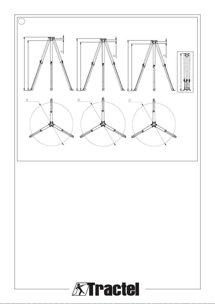
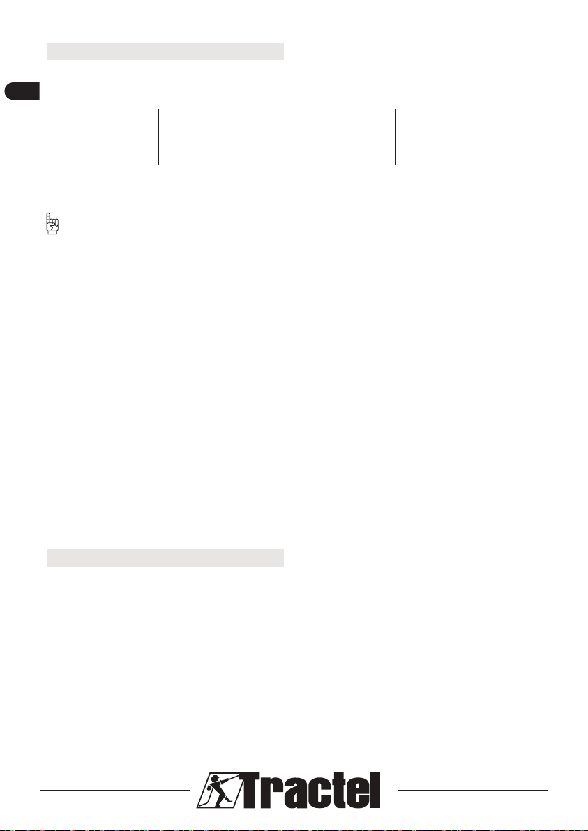
Technical specications
The dimensional specications are shown in gure 7 in
the rst part of this manual and in the table below.
Position (g. 2.c) Overall height (g. 7, HO) Height under head (g. 7, H) External diameter, feet (g. 7, DE)
2.3 1,62 m 1,51 m 1,31 m
2.2 1,57 m 1,46 m 1,27 m
2.1 1,52 m 1,41 m 1,23 m
Weight of the Tracpode PRO: 11.9 kg
Length of the Tracpode PRO when folded: 1.12 m
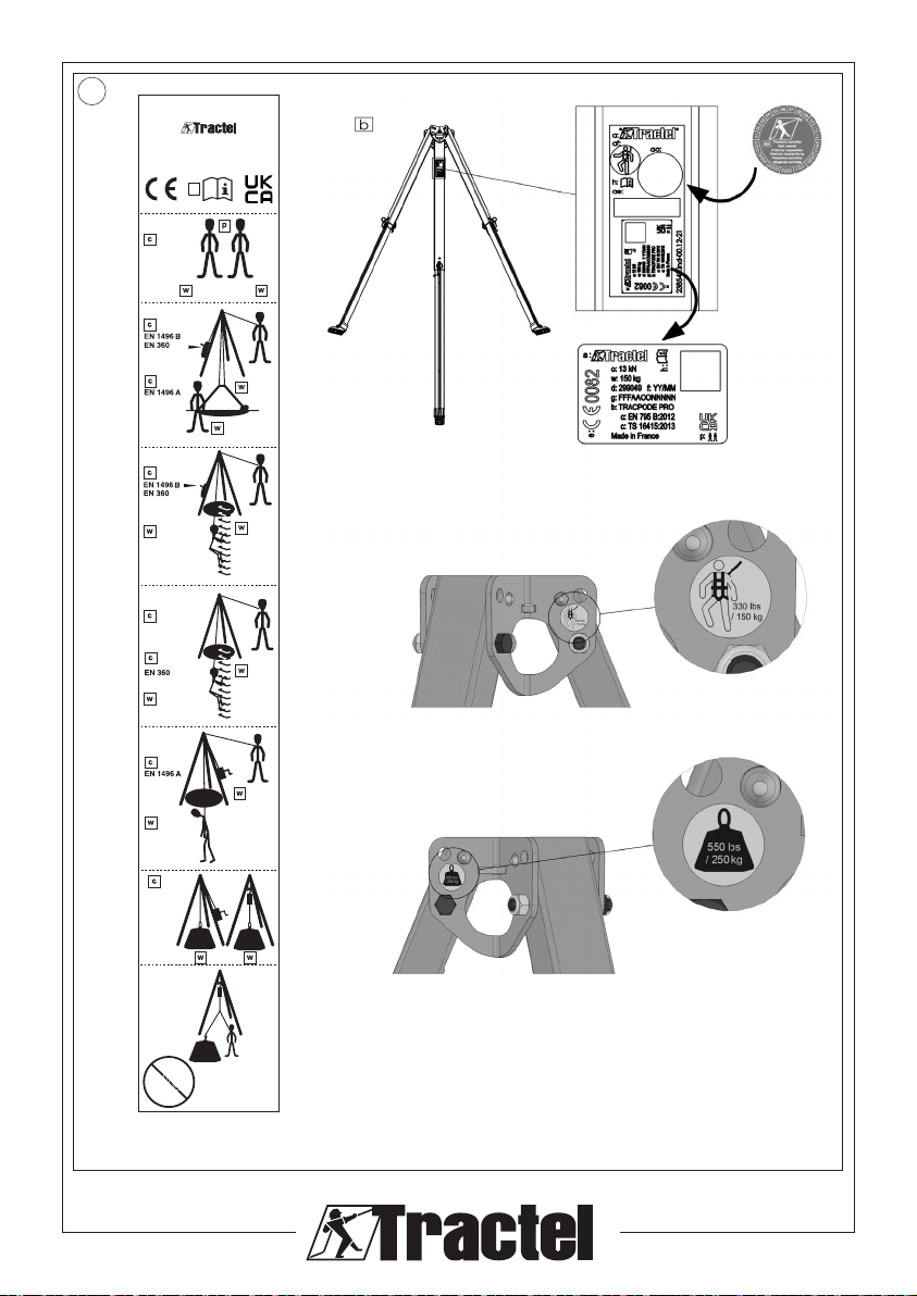
IMPORTANT: The Tracpode PRO may be used as
a temporary anchor point (EN 795-B: 2012), which can
be tted with fall-arrest systems conforming with
EN 363:2002), rescue lifting devices (conforming with
EN 1496:2017 type A or B outside CE), and devices
which allow working while suspended from a rope in
accordance with Directive 2001/45/EC.
If the Tracpode PRO is used as a system for lifting
loads, in accordance with EU Machinery Regulation
2006/42/EC, it must not be used simultaneously as a
temporary anchor point.
The Tracpode PRO is a CE-marked anchor point
covered by the European Regulation UE. The certicate
of conformity issued by the laboratory QUINTIN
CERTIFICATIONS (QC) covers its use in accordance
with the requirements stated in standard EN 795:2012
and TS 16415:2013.
The EU examination certicate of conformity issued
by QC exclude applications associated with other
directives. These other products require, depending on
what they are used for, a declaration of conformity with:
• Standard EN 1496:2017, rescue lifting devices.
• Directive 2001/45/EC, rope-suspended working
devices.
• EU Machinery Regulation 2006/42/EC, CE-marked
lifting application.
1. General warning
1. Before using a Tracpode PRO, it is essential that
the user reviews and understands the information
in the manual provided by Tractel SAS, in order to
ensure safe and eective use of the equipment.
These instructions should be made available to all
users. Further copies can be supplied on request.
2. Before using this safety equipment, it is essential to
have been trained to use it. Check the condition of
associated equipment and ensure there is enough
vertical clearance.
3. The Tracpode PRO may only be used by a single
trained and competent operator or by an operator
while overseen by a trained and competent
supervisor.
4. If a Tracpode PRO is not in good visual condition
or if it has arrested a fall, all the equipment must
be inspected by Tractel SAS or by a qualied
and competent technician, from whom written
authorisation must be given to reuse the equipment.
A visual inspection is recommended before each
use.
5. No modication or addition may be made to the
equipment without prior written approval from
TRACTEL SAS. The equipment must be transported
and stored in its original packaging.
6. Any Tracpode PRO that has not been periodically
inspected within the last twelve months, or that has
arrested a fall, must not be used. It may only be
used again following a periodic re-inspection carried
out by a qualied and competent technician who will
authorise its use in writing. If these inspections and
authorisations are not carried out, the Tracpode
PRO must be decommissioned and destroyed.
User safety is protected if the equipment is always
kept in a well-maintained state.
7. The Tracpode PRO is a fall-arrest anchor point
capable of arresting the fall of two people weighing
up to 150 kg each. The maximum operating load for
the Tracpode PRO is 150 kg.
8. If the weight of the operator, including the weight
of their equipment and tools, is between 100 kg
and 150 kg, you must ensure that the total weight
(operator, equipment + tools) does not exceed the
maximum load of each of the components of the
fall-arrest system.
9. This equipment is suitable for use on an open-air
work site and a temperature range between -40 °C
and 60 °C. Avoid contact with sharp edges, abrasive
surfaces and chemical products.
10. If the equipment will be assigned to an employee
or similar person, ensure compliance with the
applicable labour regulations.
11. The operator must be physically and mentally t
when using this equipment. If in doubt, check with
your doctor or your occupational doctor. Pregnant
women may not use this product.
12. This equipment should not be used beyond its limits
or in any situation other than that for which it is
specied: see “4. Functions and description”.

9
EN
13. It is recommended that this Tracpode PRO is
personally allocated to each operator, especially if
this is an employee.
14. Before using a Tracpode PRO, the operator must
ensure that each component is in good working
order: safety system, locking system. When setting
it up, the safety functions must not be damaged in
any way.
15. Before each use of a fall-arrest system, it is essential
to conrm the clearance beneath the operator in the
workplace, so as to avoid any risk of colliding with
the ground or with any obstacle found in the path
of a fall.
16. An EN361 full body harness is the only suitable
harness that may be used in a fall-arrest system
17. It is essential for operator safety that the device or
anchor point is correctly positioned and that work is
carried out so as to minimise the risk of falls.
18. For the operator’s safety, if the product is re-
sold outside the initial destination country, the
distributor must supply: an instruction manual and
maintenance instructions for periodic inspections
and repairs, all compiled in the language of the
product’s country of use.
19. It is essential for operator safety that the user rst
makes sure that the fall-arrest system guarantees a
fall arrest force below 6 kN.
NB:
For any special applications, please contact
TRACTEL®.
2. Denitions and pictograms
2.1. Denitions
“Supervisor”:Person or department responsible for
the management and safety of use of the product
described in the manual.
“Technician”:Person who has been trained and
certied by Tractel to carry out the maintenance
operations specied in the Annual Safety Inspection
& Maintenance Manual, in order to ensure safety and
eciency of this product.
“Operator”:Person using the product for its intended
purpose.
“End of service life date”: Refers to the point in time
after which a device or component should be replaced
and disposed of.
“Competent Person”: A person who has the
appropriate knowledge, training, and experience to carry
out the Annual Safety Inspection (ASI) in accordance
with Tractel instructions and local regulations.
“Daily Care”: Regular attention and care to the product
to ensure it is functioning properly and eciently. This
includes cleaning, lubricating, inspecting and careful
handling.
“Annual Safety Inspection (ASI)”: An operation
aimed to identify any defects, damage, or wear that
could compromise the eectiveness of the product and
potentially put employees at risk. The ASI must be done
at least every 12 months and can only be performed
by a competent person authorised to do so by the
company director.
“Maintenance”: Technical work to ensure that the
product is safe, eective, and reliable, and that it
continues to provide the necessary protection to the
operator. It is performed after a failed ASI and can
only be performed by a technician according to Tractel
Maintenance manual of this product.
“PPE”: Personal protective equipment against falls
from height.
“Connector”: Connecting element between
components of a fall-arrest system. It complies with
EN 362.
“Fall-arrest harness”: Body-retaining device designed
to arrest falls. It consists of straps and buckles. It
features fall protection attachment points marked with
an A if they may be used alone, or marked with A/2 if
they are to be used in combination with another A/2
point. It is EN 361-compliant.
“Self-retracting fall-arrest device”: Fall-arrest device
with an automatic locking function and a self-tensioning
and retraction system for the retractable lanyard. It
complies with EN 360.
“Fall-arrest system”: Assembly comprising the
following items:
– Fall-arrest harness
– Self-retracting fall-arrest device or energy absorber
or mobile fall-arrest device on rigid belaying
support or mobile fall-arrest device on exible
belaying support.
– Anchorage
– Connection element.
“Rescue lifting device” :A component or sub-
assembly of rescue equipment allowing an operator to
be winched with the help of a rescuer. It complies with
EN 1496.

10
EN
2.2. Pictograms
DANGER: Placed at the beginning of the line,
refers to instructions to avoid injury to persons, including
death, serious or minor injuries, and damage to the
environment.
IMPORTANT: Placed at the beginning of a
paragraph, indicates instructions intended to avoid
equipment failure or damage, but not directly
endangering the life or health of the operator or that of
others, and/or unlikely to cause environmental damage.
NOTE: Placed at the start of the line, indicates
instructions intended to ensure the eectiveness or
usefulness of the installation, use or maintenance
operation.
3. Operating conditions
• Check that the rubber pads are tted under the
Tracpode PRO’s feet. These pads provide the contact
with the ground and their grip secures the Tracpode
Pro if it is used without the strap. If the pads are worn,
torn or detached or if the slightest defect is visible then
the Tracpode PRO should not be used.
• Check visually the condition of the strap, the stitching
and the threads: they must not show any signs of
abrasion, fraying, burns or cuts.
• Check the feet and leg tubes: they must not be
deformed, corroded or cracked. Check all the pins
and locking buttons: they must not be deformed or
corroded.
• Check that each leg moves easily at its hinge point:
the Tracpode PRO legs should be easy to open out,
and the locking buttons should lock automatically.
• Check the condition of the associated Tracpode PRO
components (harnesses, connectors, pulleys, etc.).
• Check the complete fall-arrest system.
• Check all leg brackets used with the Tracpode PRO:
they must not be deformed, cracked or corroded.
If you have any doubts, immediately remove the
product from circulation.
IMPORTANT: All three telescopic feet of the
Tracpode PRO must be adjusted to ensure stability.
4. Functions and description
B – Head
C1 – Fall arrest anchor point
C2 – Anchor point for load lifting
D – Locking pin
E – Pad
G – Locking button
H1 – Leg
H2 – Leg for bracket
I – Pin
J – Foot
K – Retaining strap
The Tracpode PRO complies with the requirements of
standards EN 795-B:2012 and TS 16415:2013. This
equipment may be used by a maximum of two operators
weighing 150 kg protected by a fall-arrest system.
• Temperature range: -40 °C to 60 °C
• The Tracpode PRO can be used to provide access to a
conned space such as a well, storage silo, sewer, etc.
• Static load strength of the Tracpode PRO: 15 kN.
• It is made of aluminium and is lightweight (11.9 kg) with
a folded length of under 1.2 m for ease of transport.
The stability and height of the Tracpode PRO can be
adjusted using three leg positions.
IMPORTANT: The Tracpode PRO head has two
specic anchor points which must only be used for PPE
and not for load lifting equipment and another specic
anchor point which must only be used for lifting loads
and not for PPE, as indicated by the marking associated
with the point (gure 6).
The Tracpode PRO provides a temporary PPE anchor
point, which complies with the requirements stated in
standard EN 795-B:2012 and can be tted with:
• Fall-arrest devices which comply with the requirements
stated in standard EN 363 (2002)
• Rescue lifting devices, EN 1496 type A or B (2017)
outside CE
• Devices which allow working while suspended from a
rope, in accordance with Directive 2001/45/EC
• Maximum strength of the anchor point: 15 kN.
NOTE: The stated loads are the maximum
values applicable, which must not in any event be
multiplied by the number of anchor points located on
the head or legs of the Tracpode PRO device.
The pads are non-slip. The Tracpode PRO may be
used without a retaining strap.
The Tracpode PRO is supplied with a retaining strap to
secure the three legs once the device has been set up.
This retaining strap must be used when:
• Conditions for foot contact are poor.
• The feet are worn or in poor condition.
The Tracpode PRO has a basic working conguration,
and one of it’s legs can also be tted with a fall arrester
from the Blocfor R EVO range and/or a winch from the
caRol range.
IMPORTANT: The Blocfor R EVO and the caRol R
on brackets must be used in conjunction with a PPE
transfer pulley supplied by Tractel.

11
EN
4.1. Blocfor R EVO fall arrest device
The device described in this section does not fall
within the scope of CE marking for PPE as specied
in EN 795:2012.
The Blocfor R EVO is a self-retracting fall-arrest device
with a rescue lifting device. It is attached vertically to
one of the Tracpode PRO’s legs and is used to rescue,
by raising or lowering, a fallen person. The maximum
operating load for this device is 150 kg.
The cable moves freely when wound in and out at a
normal speed as the operator moves, although there is
always a gentle retraction force applied by a spring which
acts on the drum around which the lanyard is wound.
In the event of a fall, the operator is stopped by a
safety ratchet mechanism. Blocfor R EVO devices are
equipped with a manual hoist to allow the rescuer to
raise or lower the fallen operator. The winching function
can be engaged or disengaged. Winching is performed
by rotating the winder with the fold-down handle,
coupled with an automatic brake. By pressing on the
red locking button, the winder becomes operational and
can be used to wind in or wind out the cable.
The Blocfor R EVO devices have a cable length of
between 5 m and 30 m. They have a handle on the
housing for carrying the unit.
IMPORTANT: Only the Tractel bracket code
218428 can be used to attach the Blocfor R EVO to the
bracket leg of the Tracpode PRO. Blocfor R EVO
devices are not suitable for handling and securing loads.
IMPORTANT: To set up the connection of the
Blocfor R EVO cable to the Tracpode PRO head, only
the Tractel PPE fall protection pulley code 218408 is
authorised.
NOTE: The winch of the Blocfor R EVO must not
be used to raise or lower a person unless in an
emergency situation Its winching function does not
satisfy standard EN 1808:1999 on rescuing a person. It
can only be used for rescue lifting in accordance with
standard EN 1496 B (outside CE). The concept of
rescue should be understood as a one-o, non-
recurring operation.
4.2. caRol R hoist rescue lifting device
The device described in this section does not fall
within the scope of CE marking for PPE as specied
in EN 795:2012.
The caRol R manual drum hoist is used for rescue lifting
of personnel. It oers a high degree of safety in use.
Two types of hoist are available.
Type 1: caRol R TS equipped with a 20 m wheel and
worm gearbox cable, unloaded drum disengagement
and an adjustable, removable crank handle.
Type 2: caRol R PRO equipped with a 12 m cable on
the small model or a 20 m cable on the large model.
Both hoists equipped with a spur gear and a removable
handle.
IMPORTANT: Only the Tractel bracket code
218448 can be used to attach the caRol R PRO 12 hoist
to the bracket leg of the Tracpode PRO.
IMPORTANT: Only the Tractel bracket code
218468 can be used to attach the caRol R PRO 20 hoist
and the caRol R TS hoist to the bracket leg of the
Tracpode PRO.
IMPORTANT: To set up the connection of the
caRol R cable to the Tracpode PRO head, only the
Tractel PPE fall protection pulley code 218408 is
authorised.
4.3. caRol hoist load-lifting device
The device described in this section does not fall
within the scope of CE marking for PPE as specied
in EN 795:2012.
IMPORTANT: The standard EN795 of 2012 states
that it is not possible to use the Tracpode PRO
simultaneously as a load lifting anchorage point and as
a personal fall arrest anchorage point.
However, if the working environment does not allow
the operator to use any other EN 795 anchorage point
than the Tracpode PRO, then, subject to a complete
risk analysis, the operator who has to work on the lifting
device can secure himself on a Tracpode PRO PPE
anchorage point..
IMPORTANT: This paragraph only applies to load
lifting.
The anchor point for lifting complies with the
EU Machinery Regulation 2006/42/EC:
• Max. load on leg 150 kg (SWL).
• Max. load under head 250 kg (SWL).
If the ground is in good condition and stable, such as
concrete, tarmac, oor tiles, etc. and so long as the
feet and pads are in good condition (refer to the checks
before use) then the Tracpode PRO can be used
without its leg strap tted so long as the maximum load
under the head is 150 kg.
The anchor point for load lifting complies with EU
Machinery Regulation 2006/42/EC – “lifting persons”
amendment in accordance with the requirements of
standard EN 1808, suspended structures § 9.3.

12
EN
NOTE: Any operator who wants to create a
complete personnel lifting system (cradle + winch +
anchoring structure) which complies with EN 1808 must
conduct a comprehensive risk assessment and have
the solution validated by a competent organisation. The
caRol manual drum hoists are used for lifting loads.
They oer a high degree of safety in use. Two types of
hoist are available:
Type 1: caRol R TS150 equipped with a 20 m wheel and
worm gearbox cable, unloaded drum disengagement
and an adjustable, removable crank handle.
Type 2: caRol R PRO equipped with a 12 m cable on
the small model or a 20 m cable on the large model.
Both hoists equipped with a spur gear and a removable
handle.
Type 3: The caRol Duratech150 is tted with a 12 m
length rope. The winch is tted with a spur gear box and
a removable crank handle.
IMPORTANT: Only the Tractel bracket code
218448 can be used to attach the caRol R PRO 12,
caRol Duratech150 hoist to the bracket leg tube of the
Tracpode PRO.
IMPORTANT: Only the Tractel bracket code
218468 can be used to attach the caRol R PRO 20 hoist
and caRol R TS150 hoist to the bracket leg tube of the
Tracpode PRO.
IMPORTANT: To set up the connection of the
caRol R, caRol Duratech150 cable to the Tracpode
PRO head, only the Tractel load-lifting pulley code
218418 is authorised.
NOTE: The caRol R winch can be used
independently to manoeuvre a load (EU Machinery
Regulation 2006/42/EC).
5. Prohibited use
The following are strictly prohibited:
1. installing or using a Tracpode PRO without proper
permission, training and accreditation or, failing
that, without the supervision of an authorised,
trained and accredited operator
2. using a Tracpode PRO if any of the markings are
illegible
3. installing or using a Tracpode PRO without rst
verifying it thoroughly
4. using a Tracpode PRO if it has not undergone a
periodic inspection within the past 12 months by a
technician who has permitted its reuse in writing
5. using a Tracpode PRO in contradiction with the
information specied in the section “15 Service life”
6. using a Tracpode PRO if the weight of the operator,
including equipment and tools, exceeds 150 kg
7. using a Tracpode PRO with a load ranging from
100 kg to 150 kg (total weight of the operator,
equipment and tools) if any component in the fall-
arrest system has a lower safe working weight
8. using a Tracpode PRO if it has arrested a fall
9. using a Tracpode PRO as a means of maintaining
the position of a person at a place of work
10. using a Tracpode PRO in a highly corrosive or
explosive atmosphere
11. using a Tracpode PRO outside the temperature
range specied in this manual
12. using a Tracpode PRO if the vertical clearance is
inadequate in the event of a fall
13. using a Tracpode PRO if you are not in good
physical condition
14. using a Tracpode PRO if you are pregnant
15. using a Tracpode PRO if the safety function of any
of the associated items is aected by the safety
function of another item or may interfere with it
16. performing any repair or maintenance operations on
a Tracpode PRO without rst having been trained
and qualied, in writing, by TRACTEL®
17. using a Tracpode PRO if it is not complete, if it
has been dismantled beforehand or if components
have been replaced by any party not approved by
TRACTEL®
18. attaching a Tracpode PRO by any means other than
as described in this manual
19. using a Tracpode PRO as fall protection for more
than two operators
20. securing a Tracpode PRO to a bearing structure
with a strength known to be or possibly below 13 kN.
6. Installation
6.1. Setting up the Tracpode PRO
1. Place the Tracpode PRO on the ground.
2. Remove the leg locking pins (gure 2.a).
3. Set the feet to position 2.3 (gure 2.c).
4. Secure the pins (g. 2.a)
5. Lift the Tracpode PRO and keep it upright.
6. Manually unlock the leg locking buttons on the
head.
7. Move the three legs apart until they are in contact
with the central head plate.
8. Check that the legs are correctly locked to the head
by the locking buttons.

13
EN
9. The Tracpode PRO is installed.
NOTE: If the stability of the Tracpode PRO is not
satisfactory, reposition one or two locking pins to
position 2.1 or 2.2 (gure 2.c).
NOTE: If there is any doubt about the quality or
strength of the ground on which the feet stand then it is
essential to t the leg strap.
IMPORTANT: Before installing the Tracpode PRO,
check that the oor can withstand a vertical load of
13 kN distributed over the three feet.
6.2. Fitting the strap
The strap which secures the Tracpode PRO’s legs must
be tted in the following cases:
– If the ground is slippery.
– If the ground is soft or loose.
NOTE: If the ground is loose or soft, place a
plate under each foot, with sucient strength to provide
a stable support surface and to prevent the Tracpode
PRO’s feet sinking into the ground.
• Once the Tracpode PRO is installed (gure 3.a),
where necessary:
• Push the free end of the retaining strap through the
hole in the Tracpode PRO’s pads (gure 3.b).
• Then run this free end through the metal buckle tted
to the other end of the strap.
• Apply slight tension to the strap.
• The retaining strap is tted.
NOTE: For some operations the Tracpode PRO
can be secured to the ground – in this case, use pins or
anchor fastenings tted through the holes in the soles of
the Tracpode PRO’s feet.
6.3. Fitting a leg bracket to one of the
Tracpode PRO’s legs
NOTE: Three dierent systems may be tted to
the Tracpode PRO:
– Blocfor R EVO with dedicated leg bracket
– caRol R TS150 and caRol R PRO 20 with
dedicated leg bracket
– caRol R PRO 12, caRol Duratech150 with
dedicated leg bracket.
Installation of a Blocfor R EVO bracket
IMPORTANT: The Blocfor R EVO bracket must be
placed on the left-hand side of the leg tube to ensure it
is compatible with the fall arrest anchor point on the
head of the Tracpode PRO.
Once the Tracpode PRO is installed:
1. Install the bracket on the bracket leg and rest on the
foot locking pin (gure 4.a1).
2. Lock the bracket to the leg using its spring-loaded
clips (gure 4.b1).
3. The bracket is installed.
Installation of a caRol R bracket, Duratech
IMPORTANT: The caRol R bracket, Duratech must
be placed on the right-hand side of the leg tube to
ensure it is compatible with the load-lifting anchor point
on the head of the Tracpode PRO.
Once the Tracpode PRO is installed:
1. Place the bracket on the bracket leg and rest on the
foot locking pin (gure 4.a2).
2. Lock the bracket to the leg using its spring-loaded
clips (gure 4.b2).
3. The bracket is installed.
6.4. Installing a pulley on a head anchor
point
Installation of a PPE pulley for Blocfor R EVO
IMPORTANT: Only a Tractel PPE pulley marked
150 kg EN 1496 may be used in conjunction with the
Blocfor R EVO.
Once the Tracpode PRO is installed:
1. Open the quick-link connector nut.
2. Attach the quick-link connector to the PPE anchor
point on the head of the Tracpode PRO, located on
the left-hand side of the bracket leg.
3. Position the pulley in a horizontal position and
rotate the pulley ange through the opening in the
quick link (gure 5.a).
4. Let the pulley hang open.
5. The pulley is installed.
Installation of a lifting pulley for caRol R
IMPORTANT: Only a Tractel lifting pulley marked
150 kg 2006/42/CE may be used in conjunction with the
caRol R, Duratech.
Once the Tracpode PRO is installed:
1. Open the quick-link connector nut.
2. Attach the quick link to the load-lifting anchor point
on the head of the Tracpode PRO, located on the
right-hand side of the bracket leg.

14
EN
3. Position the pulley in a horizontal position and
rotate the pulley ange through the opening in the
quick link (gure 5.a).
4. Let the pulley hang open.
5. The pulley is installed.
6.5. Putting in place the cable on a cable
transfer pulley
1. Pull the cable of the device (gure 5.b).
2. Place the cable in the open pulley (gure 5.b).
3. Tilt the pulley plate into the quick-link opening
(gure 5.c).
4. Tighten the quick-link nut (gure 5.d).
5. Check that the pulley turns freely by manually
pulling on the end of the cable.
6. The pulley is installed.
6.6. Fitting a fall arrester to the Tracpode
PRO head
The head of the Tracpode PRO provides three anchor
points. Testing has determined that it is capable of
providing protection in the event of two operators falling
at the same time. Never connect both fall protection
systems to the same anchor point. To use a rope-
suspended work device, it is mandatory to separate
the operator suspension anchor and the fall protection
anchor. The connection with the anchor point must be
made using an EN 362 connector. For details about
connecting the fall-arrest system to the fall-arrest
harness, refer to the manual for the PPE used.
DANGER: Before and during use, it is necessary
to consider how any rescue can be conducted eciently
and safely, within 15 minutes. After that time, the
operator is in danger.
6.7. Installing a load lifting device on the
Tracpode PRO head
The device described in this section does not fall
within the scope of CE marking for PPE as specied
in EN 795:2012.
IMPORTANT: This paragraph only applies to load
lifting. The anchor point for lifting conforms with EU
Machinery Regulation 2006/42/EC. The head of the
Tracpode PRO is tted with three anchor points.
Testing has determined that the Tracpode PRO can
support a total load of 150 kg. The attachment to the
anchor point must be made using an accessory which
complies with the requirements stated in the machinery
directive, and which is capable of supporting the load
concerned.
IMPORTANT: The standard EN795 of 2012 states
that it is not possible to use the Tracpode PRO
simultaneously as a load lifting anchorage point and as
a personal fall arrest anchorage point.
However, if the working environment does not allow
the operator to use any other EN 795 anchorage point
than the Tracpode PRO, then, subject to a complete
risk analysis, the operator who has to work on the lifting
device can secure himself on a Tracpode PRO PPE
anchorage point.
DANGER
Before and during use, it is necessary to consider
how any rescue can be conducted eciently
and safely, within 15 minutes. After that time, the
operator is in danger.
7. Components and materials
• Tubes: anodised aluminium.
• Head, pins, fastenings, pulley ange: galvanised steel.
• Strap: polypropylene.
• Pulley: Glass-bre reinforced PA.
• Pulley spindle: stainless steel.
• Pad: Rubber-reinforced polypropylene.
8. Associated equipment
8-Fall-arrest system (EN 363)
• Fall-arrest system (EN 353-1/2 – EN 355- EN 360)
• Anchor point (EN 795)
• Connector (EN 362)
• Full body (fall arrest) harness (EN 361)
• Rescue lifting device (EN 1496 A or B).
Before using a fall-arrest system, ensure that each
component is usable and functioning correctly.
9. Daily care, transport and storage
To perform the daily care, use only clear, cold water, a
mild detergent for fabrics, and a synthetic brush.
After washing or if during use, the product is wet, allow
it to dry naturally in a shaded location away from any
source of heat.
During transport and storage, protect the equipment in
a dry packaging against any danger (shock, source of
direct heat, chemical products, UV radiation, etc).
For accessories, see the specic manuals of the
associated products.

15
EN
10. Equipment compliance
TRACTEL SAS RD 619 – Saint-Hilaire-sous-Romilly
– F-10102 Romilly-sur-Seine France hereby declares
that the safety equipment described in this manual:
1) EU regulation
• complies with the provisions of Regulation (EU)
2016/425 of the European Parliament of March 2016
• is identical to the PPE which has been the subject of an
“EU” type examination issued by Quintin Certications
– 825 ROUTE DE ROMANS 38160 SAINT ANTOINE
L’ABBAYE – France, identied by the number 2927,
which issued type certication after conducting testing
in accordance with standards EN 795 B (2012) and
TS 16415 (2013).
• is subject to the procedure referred to in Annex VIII of
Regulation (EU) 2016/425 of the European Parliament,
module D, under the control of a notied body APAVE
Exploitation France SAS – 6 Rue du Général Audran
– 92412 COURBEVOIE cedex – France, identied by
the number 0082.
2) UKCA regulation
complies with Regulation (EU) 2016/425 as amended
to apply in the United Kingdom.
11. Marking
The Tracpode PRO is tted with the following marking
labels (gure 6):
– A label on the inside of the bracket leg tube containing
the following markings (gure 6.a):
a. The trademark: TRACTEL
b. The product description
c. The reference standards followed by the year of
application
d. The product reference: ex 010642
e. The CE logo followed by the number 0082,
identication number of the notied body responsible
for the production inspection
f. Year and month of manufacture
g. Serial number
h. A pictogram showing that the manual must be read
before use
o. The minimum breaking strength of the anchor device
p. The number of individuals that can use the equipment
w. The maximum working load
aa. The date of the next periodic inspection.
– A label on the outside of the bracket leg containing
gures representing the use scenarios for the
Tracpode PRO with its accessories (gure 6.b).
A label is located on the right-hand head side of the
bracket leg tube to indicate the load-lifting anchor
point (gure 6.c). A label is located on the left-hand
head side of the bracket leg tube and on the opposite
side to indicate the two anchor points for fall arresters
(gure 6.d).
12. Periodic inspection and repair
This product must undergo an ASI. Depending on
the frequency of use, environmental conditions and
regulations of the company or the country of use, the
ASI may be more frequent.
Depending on the results of the inspection, maintenance
may be required.
A written conrmation of the product tness for use
must be done after an ASI by a competent person or
after maintenance by a technician. All records must
be kept with the product logbook. After arresting a
fall, this product must undergo an ASI to determine its
tness for use or the need for maintenance. Any textile
components of the product must be replaced, even if
they do not appear damaged.
The following points must be examined:
1. Presence and legibility of marking
2. Check that the three screws and nuts are present
on the head.
3. Tighten the screws (20 Nm±3).
4. Presence and condition of the feet locking pins and
associated pins
5. Presence and condition of the leg locking buttons
6. No deformation, cracking, impact or oxidation
7. Free rotation of the legs during opening and closing
8. The telescopic tubes slide freely in the leg tubes.
9. Presence and condition of the rods
10. No deformation or wear of the lifting and fall arrest
anchor points (max. 2 mm)
11. Condition of the retaining strap
The outcome of these ASIs must be recorded in the
inspection register located at the centre of these
instructions, which must be kept throughout the life of
the product until it is taken out of service.
The technician must also complete lines A to E of the
table with the following information:
A: Name of inspector
B: Date of inspection
C: Inspection result OK/Not OK
D: Signature of inspector
E: Date of next inspection.
IMPORTANT: Regular periodic examinations are
essential. The safety of the user depends upon the
continued eciency and durability of the equipment.

16
EN
IMPORTANT: It is essential that repairs are carried
out by a technician in strict compliance with the
instructions provided by Tractel.
13. Service life
To ensure safe and eective use of this product, it is
mandatory to follow these guidelines:
• Use the product strictly according to the instructions
provided in this manual.
• Have a competent person perform an ASI at least
every 12 months to conrm it is still safe to use, and
get written conrmation of its tness for use.
• Store and transport the product in accordance with the
instructions in this manual.
Providing that these guidelines are strictly followed, the
product will have an unlimited lifespan.. If the product
includes textile components, these components must
be replaced after a maximum of 20 years from their
date of manufacture.
14. Disposal
When disposing of the product, it is mandatory to recycle
the various components after sorting metallic materials
and sorting synthetic materials. These materials must
be recycled through specialist organisations. When
disposing the product, a qualied person should
dismantle and separate the component parts.
15. Manufacturer’s name and address:
Tractel SAS – RD 619 – BP 38
Saint-Hilaire-sous-Romilly 10102
Romilly-sur-Seine France

17
EN
16. Inspection register
Type of product
Type de produit
Produktbezeichnung
Produkttype
Tipo de producto
Tipo di prodotto
Tipo de produto
Τύπος προϊόντος
Produkttype
Produkttyp
Tuotetyyppi
Produkttype
Typ produktu
Тип изделия
Product reference
Référence produit
Codenummer
Produktcode
Referencia producto
Riferimento prodotto
Referência do produto
Κωδικός προϊόντος
Produktreferanse
Produktreferens
Tuotteen viitenumero
Produktnummer
Oznaczenie produktu
Артикул изделия
Serial number
Numéro de série
Seriennummer
Serienummer
Numero de serie
Numero di serie
Número de série
Σειριακός αριθμός
Serienummer
Serienummer
Sarjanumero
Serienummer
Numer seryjny
Серийный номер
Name of user
Nom de l’utilisateur
Name des Benutzers
Naam van de gebruiker
Nombre del usuario
Nome dell’utilizzatore
Nome do utilizador
Όνομα του χρήστη
Brukerens navn
Användarens namn
Käyttäjän nimi
Brugerens navn
Nazwisko użytkownika
Фамилия пользователя
Date of manufacturing
Date de fabrication
Herstellungsdatum
Fabricagedatum
Fecha de fabricación
Data di produzione
Data de fabrico
Ημερομηνία κατασκευής
Fabrikasjonsdato
Tillverkningsdatum
Valmistuspäivä
Fabrikationsdato
Data produkcji
Дата производства
Date of purchase
Date d’achat
Kaufdatum
Aankoopdatum
Fecha de compra
Data di acquisto
Data de compra
Ημερομηνία αγοράς
Kjøpedato
Inköpsdatumi
Ostopäivä
Købsdato
Data zakupu
Дата покупки
X=Date of commissioning
X=Date de mise en service
X=Datum der Inbetriebnahme
X=Datum ingebruikneming
X=Fecha de puesta en servicio
X=Data di messa in servizio
X=Data de entrada em serviço
X=Ημερομηνία θέσης σε λειτουργία
X=Dato for bruk første gang
X=Första användningsdagen
X=Käyttöönottopäivä
X=Dato for ibrugtagning
X=Data przekazania do użytku
X=Дата ввода в эксплуатацию
No XX+1 X+2 X+3 X+4 X+5 X+6 X+7 X+8 X+9 X+10
1
2
3
4
5
6
7
8
9
10
11
12
13
A
B
C
D
E

18
FR
Spécications techniques
Les spécications dimensionnelles sont indiquées sur
la gure 7 en première partie du présent manuel ainsi
que dans letableau si dessous.
Position (g. 2.c) Hauteur hors tout (g.7, HO) Hauteur sous tête (g.7, H) Diametre exterieur pieds (g.7, DE)
2.3 1,62 m 1,51 m 1,31 m
2.2 1,57 m 1,46 m 1,27 m
2.1 1,52 m 1,41 m 1,23 m
Poids du Tracpode PRO :11,9 kg
Longueur du Tracpode replié : 1,12 m
IMPORTANT : le Tracpode PRO peut être utilisé
comme point d’ancrage temporaire (EN795-B : 2012),
pouvant recevoir des systèmes d’arrêt des chutes
conformes à l’EN363:2002, des dispositifs de
sauvetage par élévation conformes à l’EN1496:2017
type A ou B en dehors du CE, des dispositifs de travail
en suspension sur corde conformes à la directive
2001/45/CE.
En cas d’utilisation comme système de levage de
charge conforme au règlement 2006/42/CE, il ne doit
pas être utilisé simultanément comme point d’ancrage
EPI temporaire.
Le Tracpode PRO est un point d’ancrage CE couvert par
le Règlement Européen UE. Le certicat de conformité
délivré par le laboratoire QUINTIN CERTIFICATION
(QC) couvre son utilisation conformément aux
exigences de la norme EN 795:2012 et TS16415:2013.
Le certicat de conformité au Règlement Européen
UE délivré par QC exclue les applications associées
aux autres directives. Ces autres produits font l’objet
en fonction de leur utilisation d’une déclaration de
conformité à la :
• Norme EN1496:2017, système de sauvetage par
élévation.
• Directive 2001/45/CE, dispositifs de travail en
suspension sur corde.
• Règlement 2006/42/CE, application CE levage.
1. Consignes prioritaires
1. Avant d’utiliser un Tracpode PRO, il est
indispensable pour la sécurité d’emploi du matériel
et son ecacité que l’utilisateur lise et comprenne
les informations dans la notice fournie par
TRACTEL SAS. Cette notice doit être conservée
à disposition de tout utilisateur. Des exemplaires
supplémentaires peuvent être fournis sur demande.
2. Avant d’utiliser ce matériel de sécurité il est
indispensable d’avoir reçu une formation à son
emploi. Vérier l’état des équipements associés et
assurez-vous que le tirant d’air est susant.
3. Le Tracpode PRO ne peut être utilisé que par
un seul opérateur formé et compétent ou par un
opérateur sous la surveillance d’un utilisateur.
4. Si un Tracpode PRO n’est pas en bon état apparent
ou s’il a servi à l’arrêt d’une chute, l’ensemble de
l’équipement doit être vérié par TRACTEL SAS
ou par un technicien habilité et compétent qui
doit autoriser par écrit la réutilisation du système.
Un contrôle visuel avant chaque utilisation est
recommandé.
5. Toute modication ou adjonction à l’équipement
ne peut se faire sans l’accord préalable écrit de
TRACTEL SAS. L’équipement doit être transporté
et stocké dans son emballage d’origine.
6. Tout Tracpode PRO n’ayant pas fait l’objet d’un
examen périodique au cours des douze derniers
mois ou ayant arrêté une chute, ne doit pas être
utilisé. Il ne pourra être utilisé de nouveau qu’après
un nouvel examen périodique réalisé par un
technicien habilité et compétent qui autorisera
par écrit son utilisation. À défaut de ces examen
et autorisation, le Tracpode PRO sera réformé et
détruit. La sécurité de l’utilisateur est étroitement
liée au maintien de l’ecacité et de la résistance
de l’équipement.
7. Le Tracpode PRO est un point d’ancrage antichute
pouvant retenir la chute de deux personnes de
150 kg maximum chacun. La charge maximale
d’utilisation est de 150 kg pour le Tracpode.
8. Si la masse de l’opérateur augmentée de la masse
de son équipement et de son outillage est comprise
entre 100 kg et 150 kg, il est impératif de s’assurer
que cette masse totale (opérateur + équipement
+ outillage) n’excède pas la charge maximale
d’utilisation de chacun des éléments constituant le
système d’arrêt des chutes.
9. Cet équipement convient pour une utilisation
sur chantier à l’air libre et pour une plage de
température comprise entre -40°C et +60°C. Éviter
tout contact avec des arêtes vives, des surfaces
abrasives, des produits chimiques.
10. Si vous devez coner l e matériel à u n personnel
salarié ou assimilé, conformez-vous à la
réglementation du travail applicable.

19
FR
11. L’opérateur doit être en pleine forme physique
et psycho logique lors de l’utilisation de cet
équipement. En cas de doute, consulter son
médecin ou le médecin du travail. Interdit aux
femmes enceintes.
12. L’équipement ne doit pas être utilisé au-delà de
ses limites, ou dans toute autre situation que celle
pour laquelle il est prévu : cf. « 4. Fonctions et
description ».
13. Il est recommandé d’attribuer personnellement le
Tracpode à chaque opérateur, notamment s’il s’agit
de personnel salarié.
14. Avant l’utilisation d’un Tracpode, l’opérateur doit
s’assurer que chacun des composants est en bon
état de fonctionnement : système de sécurité,
verrouillage. Lors de la mise en place, il ne doit pas
y avoir de dégradation des fonctions de sécurité.
15. Dans un système d’arrêt des chutes, il est essentiel
de vérier l’espace libre sous l’opérateur sur le lieu
de travail avant chaque utilisation, de manière qu’en
cas de chute il n’y ait pas de risque de collision avec
le sol ni présence d’un obstacle sur la trajectoire
de la chute.
16. Un harnais d’antichute EN361 est le seul dispositif
de préhension du corps qu’il est permis d’utiliser
dans un système d’arrêt des chutes.
17. Il est essentiel pour la sécurité de l’opérateur que
le dispositif ou le point d’ancrage soit correctement
positionné et que le travail soit eectué de manière
à réduire au minimum le risque de chutes ainsi que
sa hauteur.
18. Pour la sécurité de l’opérateur, si le produit est
revendu hors du premier pays de destination,
le revendeur doit fournir : un mode d’emploi, des
instructions pour l’entretien, pour les examens
périodiques et les réparations, rédigés dans la
langue du pays d’utilisation du produit.
19. Il est essentiel pour la sécurité de l’opérateur, que
l’utilisateur se soit assuré que le système d’arrêt
des chutes garantit un eort d’arrêt de la chute
inférieur à 6 kN.
NOTE
Pour toute application spéciale, n’hésitez pas à
vous adresser à TRACTEL®.
2. Dénitions et pictogrammes
2.1. Dénitions
« Superviseur »: Personne ou service responsable de
la gestion et de la sécurité d’utilisation du produit décrit
dans le manuel.
« Technicien »: Personne formée et certiée par
Tractel pour eectuer les opérations de maintenance
spéciées dans la notice des inspections annuelles de
sécurité et le manuel de maintenance, an de garantir
la sécurité et l’ecacité de ce produit.
« Opérateur »: Personne opérant dans l’utilisation du
produit conformément à la destination de celui-ci.
« Date de n de vie » : désigne le moment après lequel
un appareil ou un composant doit être remplacé et mis
au rebut.
« Personne compétente » : une personne qui possède
les connaissances, la formation et l’expérience
appropriées pour eectuer l’inspection annuelle de
sécurité (ASI) conformément aux instructions de Tractel
et aux réglementations locales.
« Entretien quotidien » : attention et soin
réguliers apportés au produit pour garantir son bon
fonctionnement et son ecacité. Cela comprend
le nettoyage, la lubrication, l’inspection et une
manipulation soigneuse.
« Inspection Annuelle de Sécurité (ASI ) » : opération
qui vise à identier tout défaut, dommage ou usure
qui pourrait compromettre l’ecacité du produit et
potentiellement mettre en danger les salariés. L’ASI
doit être eectué au moins tous les 12 mois et ne
peut être eectué que par une personne compétente,
habilité par le chef d’entreprise
« Maintenance » : intervention technique qui permet de
garantir que le produit est sûr, ecace et able, et qu’il
continue à fournir la protection nécessaire à l’Opérateur.
Elle est eectuée après un échec d’ASI et ne peut être
eectuée que par un technicien conformément au
manuel de maintenance Tractel de ce produit.
« EPI »: Équipements de Protection Individuelle contre
les chutes de hauteur.
« Connecteur »: Élément de connexion entre
composants d’un système d’arrêt des chutes. Il est
conforme à la norme EN 362
« Harnais d’antichute »: Dispositif de préhension
du corps destiné à arrêter les chutes. Il est constitué
de sangles et bouclerie. Il comporte des points
d’accrochage antichute marqués d’un A s’ils peuvent
être utilisés seuls, ou marqués d’un A/2 s’ils doivent
être utilisés en combinaison avec un autre point A/2. Il
est conforme à la norme EN 361.
« Antichute à rappel automatique »: Antichute avec
une fonction de blocage automatique et un système
automatique de tension et de rappel pour la longe
rétractable. Il est conforme à la norme EN 360

20
FR
« Système d’arrêt des chutes »: Ensemble composé
des éléments suivants :
– Harnais d’antichute.
– Antichute à rappel automatique ou absorbeur
d’énergie ou antichute mobile sur support
d’assurage rigide ou antichute mobile sur support
d’assurage exible.
– Ancrage.
– Élément de liaison.
« Dispositif de sauvetage par élévation »: Composant
ou sous ensemble d’un équipement de sauvetage
permettant le treuillage d’un opérateur avec l’aide d’un
sauveteur .il est conforme à la norme EN 1496
2.2. Pictogrammes
DANGER : Placé en début de ligne, désigne des
instructions destinées à éviter des dommages aux
personnes, notamment les blessures mortelles, graves
ou légères, ainsi que les dommages à l’environnement.
IMPORTANT : Placé en début de ligne, désigne
des instructions destinées à éviter une défaillance ou
un dommage des équipements, mais ne mettant pas
directement en danger la vie ou la santé de l’opérateur
ou celles d’autres personnes, et/ou n’étant pas
susceptible de causer de dommage à l’environnement.
NOTE : Placé en début de ligne, désigne des
instructions destinées à assurer l’ecacité ou la
commodité d’une installation, d’une utilisation ou d’une
opération de maintenance.
3. Conditions d’utilisation
• Vérier les patins en caoutchouc sous les pieds du
Tracpode PRO : ils sont en contact avec le sol et
garantissent la tenue, l’adhérence des patins du
Tracpode PRO s’il est utilisé sans sangle. Si les
patins sont usés, arrachés, décollés, s’ils présentent
le moindre défaut visuel, il ne faut pas utiliser le
Tracpode PRO.
• Vérier visuellement l’état de la sangle, des coutures,
les ls de couture : ils ne doivent pas présenter de
traces d’abrasion, d’elochage, de brûlures, de
coupures.
• Vérier les tubes de pieds et jambes : Ils ne doivent
pas être déformés, corrodés, ssurés. Vérier
l’ensemble des broches et boutons de verrouillage, il
ne doivent pas être déformés, corrodés.
• Vérier la rotation des jambes autour des vis
d’articulation : ouverture facile des jambes du
Tracpode PRO, verrouillage automatique des boutons
de verrouillage.
• Vérier l’état des composants associés au Tracpode
PRO : (harnais, connecteurs, poulies ect.).
• Vérier le système d’arrêt des chutes complet.
• Vérier l’ensemble des consoles xées sur le trépied :
elles ne doivent pas être déformées, ssurés,
corrodées.
En cas de doute, retirer immédiatement tout produit de
la circulation.
IMPORTANT : Les trois jambes du Tracpode
doivent être réglées pour en garantir la stabilité.
4. Fonctions et description
B – Tête
C1 – Point d’ancrage antichute de personne
C2 – Point d’ancrage pour levage de charge
D – Broche de réglage
E – Patin
G – Bouton de verrouillage
H1 – Jambe.
H2 – Jambe pour console
I – Goupille
J – Pied
K – Sangle de maintien
Conforme aux normes EN795B:2012 et TS16415:2013.
Cet équipement peut être utilisé par deux personnes
de 150 kg maximum équipées de système d’arrêt des
chutes
• Température d’utilisation : -40 °C à 60 °C
• Le Tracpode permet d’accéder à un espace conné,
puits, silo, égouts, etc.
• Résistance statique du Tracpode : 15 kN.
• Il est fabriqué en aluminium, ainsi son faible poids de
11.9 kg ainsi qu’une longueur repliée inférieur à 1.2 m
en facilite le transport.
La stabilisation ainsi que la hauteur du Tracpode PRO
peuvent être réglées grâce à trois positions de réglage
des pieds.
IMPORTANT : La tête de Tracpode PRO est
composée de deux points d’ancrage spécique qui
doivent être utilisés uniquement pour un EPI et non
pour un équipement de levage et d’un point d’ancrage
spécique qui doit être utilisé uniquement pour le
levage de charge et non pour un EPI selon le marquage
associé au point (gure 6).
Point d’ancrage temporaire EPI conforme aux exigences
de la norme EN795B:2012 pouvant recevoir :
• Des antichutes conformes aux exigences de la norme
EN 363 (2002).
• Des dispositifs de sauvetage par élévation EN 1496
type A ou B (2017) en dehors du CE.
• Des dispositifs de travail en suspension sur corde
conformes à la directive 2001/45/CE
• Résistance maximale point d’ancrage : 15 kN
This manual suits for next models
1
Table of contents
Languages: