Alkamedi AMS 4100 User manual

DIGITAL WATER IONIZER
AMS4100AMS41005
Operation Manual
'fence.

Contents DIGITAL WATER IONIZER
SAFETYINSTRUCTIONS
APPEARANCEAND FUNCTIONALSTRUCTURE
INSTALLATION
PACKAGECONTENTS
HOWTO OPERATE
HOWTO PRODUCEALKALINE IONIZEDWATER
HOWTO PRODUCEACIDIC IONIZEDWATER
HOWTO PRODUCEPURIFIEDWATER
MELODYON/OFF&VOLUMEADJUSTMENT
FILTERREPLACEMENT
FILTERCOMPOSITION
pH VALUETEST
TROUBLESHOOTING
UNITSPECIFICATIONS
WARRANTYCARD
3
7
9
13
14
15
16
17
18
19
22
23
24
26
27

SAFETY INSTRUCTIONS |,', '
O IG ITAL WATE R IQ N IZE R
^Warning symbol to indicate importance of danger such as fire
and personal injury.
Caution symbol to indicate precautions and damage to the unit.
Disclaimer:
TheWaterionizer isa water purification product.
Pleaseensure correct usage ofthis product and thatyou have readthe instructionsfully.
Ifyou feelyou are experiencing adverse effects and pain persists, pleaseconsult a healthcare professional.
Thisappliance must not be used by persons(including children) with reduced physical,sensory or mental
capabilities, or lack of experience and knowledge, unlessthey have been givensupervision or instruction.
Children must be supervised notto play with this appliance.
For boner drinking:
Always discard the intial dispensed water as a precaution. This will ensure the integrity of the desired
"strength"level selected.
initially, drink a small amount of level 1 Alkaline water, thereafter increasing level relative to personal
tolerance and understanding of personal need
In order to not compromise the integrity of prescribed medicine, ensure 'purified water' is selected to
take with any medicine prescribed by an authorized medical practitioner.
Optimum drinking levels are based on a normal distribution of the populations needs, it is not
recommended by the manufacturer to drink higher than pH 10.
bk

SAFETY INSTRUCTIONS DIGITAL WATER IONIZER
A When the unit is imersed into water, pull out the power plug
KB|fl immediately and then take the unit out of the water.
Avoid an electric circuit overload of an outlet or electric wiring.
Connect the unit power plug to the correspondent AC voltage
outlet.
> Ensuring the unit is connected directly and solely to a power supply
will avoid overloading the appliance and reduce risk factor.
k Do not touch the power plug with the wet hands when you put it in
KlEl/|ll or out of a wall outlet.
^
^
> If the plug.-in fitting is not stable, it may cause an electric shock or
If the supplied cord is damaged, it must be replaced by the
manufacturer, it's service agent or qualified persons. Please refer
this condition to your seller and enforce manufacturer's warranty
as per the Warranty Card instructions.
I
Do not install the unit in a place of below-freezing temperature
or near any fire source.
> Correct environment temperature range: 10 ~ 35oC (50~95oF)
Correct inflow water temperature: 5 ~ 30oC (41~86oF)
^
O>oEntxtrotei!talell~~nZ~tn~aln~~ts!reun'~a9hyt~causethe exterior unit body
to discolor and may cause the entire unit to warp/twist the casing.
This may result in mechanical failure,
> Extreme environmental exposure may cause the exterior unit body
Always Install the unit on a horizontally flat surface.

SAFETY INSTRUCTIONS I,', '
DIGITAL WATER IONIZER
^Do not disassemble, repair and/or modify in any situation.
> Persona!safety could be compromised.
> For repair, please contact our authorized sales agent.
cs)
( ! ) Do not use any other wafer than sanitary drinkable safe wafer
(municipal water etc).
( Va\ Let the unit have water input and output for
2~3 minutes before the Ist hand operation of the unit after installation.
Never allow hot water input into the unit.
This may cause severe damage to it's interior,
especially the filter and ionization chamber.
> Optimum input water temperature: 5~30oC (41~86oF)
c]
BAK
P.
:> J
( A Never spray the unit with water,
^II nor clean the unit with water or other liquid.
> Recommend cleaning with a micro fibre or soft cloth.
A Do not clog, bend, twist or kink the water inletand outlet hoses.
^ > Ensurewaterhosesarenotconstrictedtoensurecorrectwaterflowinandoutoftheunit.
C]
4
(

t4_1\',lhfff!:AKIESESE SAFETY INSTRUCTIONS DIG,TAL WATER IONIZER
Do not give too high a drawing tension to the power cord when you pull the cord out of a socket.
Keep the unit in a dry environment.
Keep the unitclean away from dust, hot temperature, sunlight, salts, chemicals, etc.
Do not attempt to modify the color, shape, or appearance of the unit.
Clean the unitwith asoft, dry, washcloth.
Foroptimum performance, keep the unit in a clean condition.
^Do not place the pH test reagent / liquid near an open flame.
> The pH test reagent is flammable.
Do not use an Aluminum (weak against alkaline liquid),
copper (weak against acid) or other metallic receptacle to
store ionized water.
> Glass or ceramic containers are recommended.
Do not drink ionized or purified water after being stored for
a longer period than 3 days.
ionized water is no longer ionized after a period of storage.
ionized water is best used fresh.
! )
Take care when handling the pH reagent.
^ > Incase of accidental consumptionof thetest liquid, inducevomitingand immediatelyseek medicaladvice.
KB|fl > Incase of accidental splashing into eyes, wash it off with clean water, and seek medical assistance.
> Incase accidental splashing on skin, wash it off with water.
> Keep the pH test liquid kit out of children' s reach.

EIlEIITA wAT ER ID Nil zE R APPEARANCEANDFUNCTIONALSTRUCTURE,,', '
1,Front Panel
2,Alkaline Water Spout
|-AMS 4100:Straight Spout
-AMS41005: FlexibleSpout
3. LCD Screen (Function Indicator)
4. Touch Buttons
5. Operation Knob(WaterSupply Control Valve)
6. Main PowerSwitch
7, Fuse Holder
~(.
-@
8. FilterConnectionTerminal
- A filtercartridgemustbe connectedto theterminal
whenthefilterisreplacedwithanewone
9, Speaker
10. Holesfor Wall-mount
11 FilterCover
12,Back Panel
13.Spec. Label
14.Water Inlet Port
- Connect with a water supply hose
15.AC PowerCord
16. BottomBase
17.Drain WaterPort
@

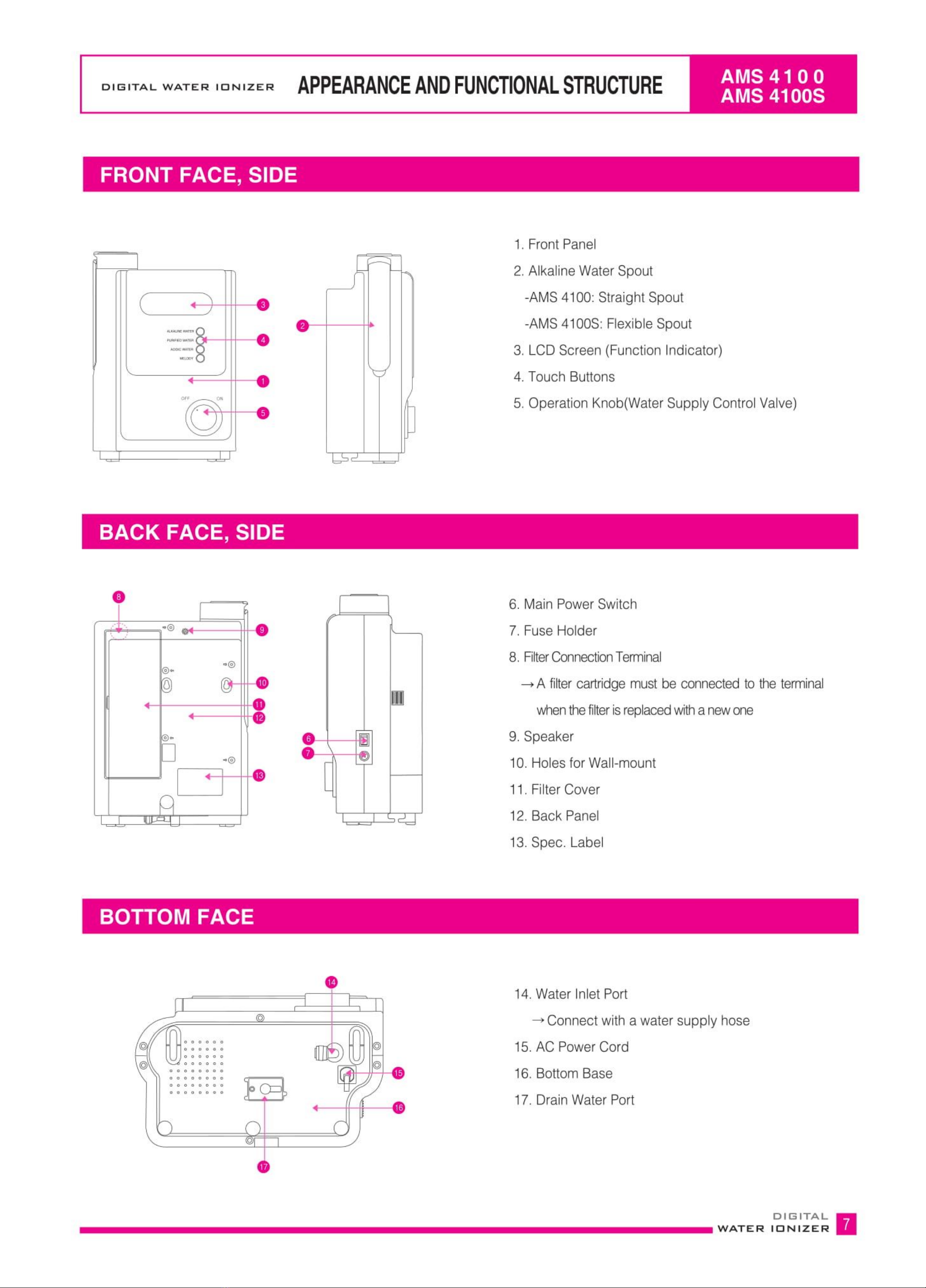
PA_,,`,bII,A KfXI EOE APPEARANCEANDFUNCTIONALSTRUCTUREo' G IT A L wA T E R IIo N IIz E R
0
. 8@
FilterLife[
-rIlNCLllI IC; / /B -
o
46
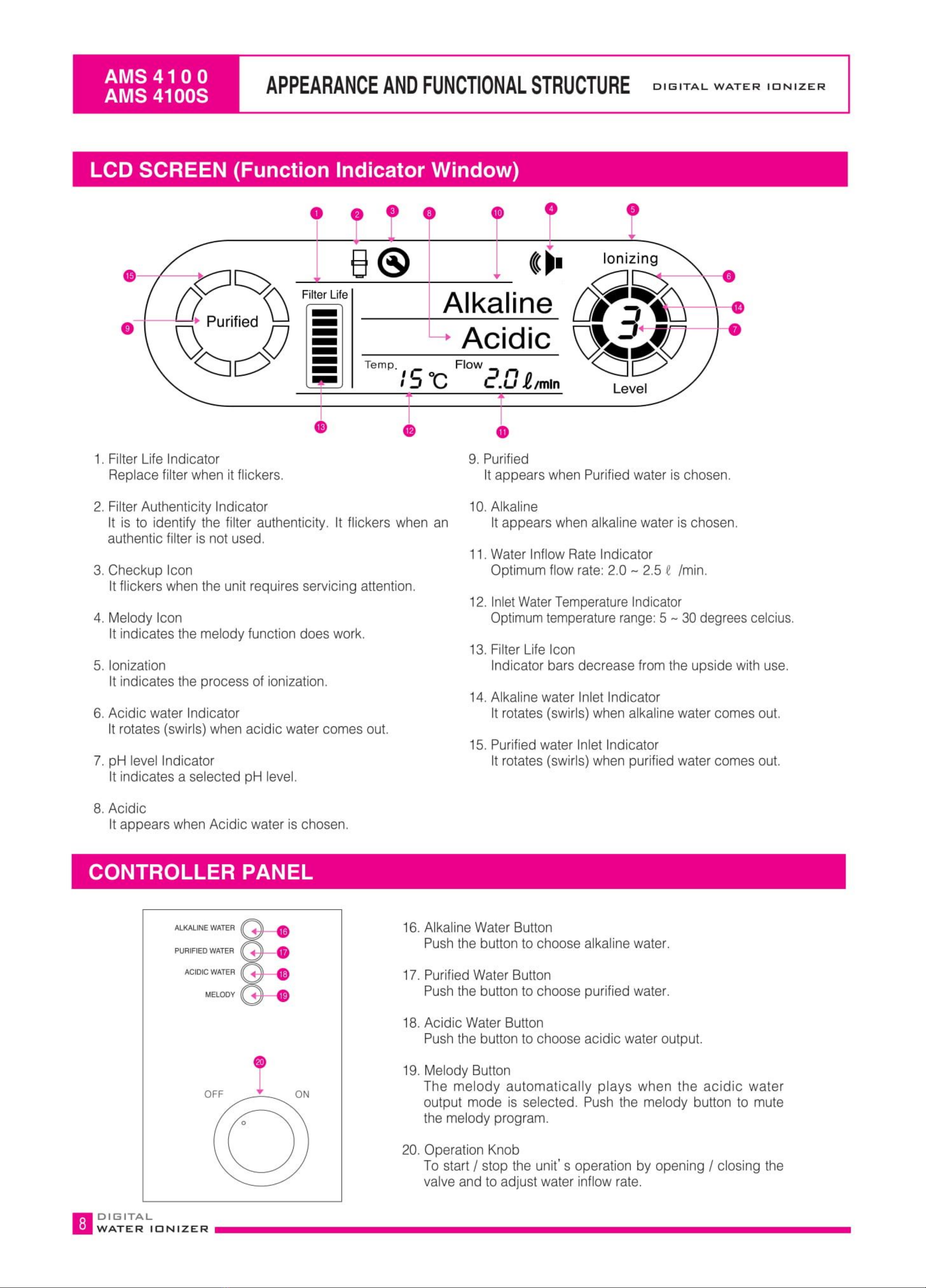
1, FilterLife Indicator
Replace filter when it flickers.
2, FilterAuthenticity Indicator
It is to identify the filter authenticity, It flickers when
authentic filter is not used.
3, Checkup Icon
Itflickers when the unit requiresservicing attention.
4, Melody Icon
It indicates the melody function does work.
5, ionization
It indicates the process of ionization,
6, Acidic water Indicator
It rotates(swirls) when acidic water comes out,
7, pH level Indicator
It indicates a selected pH level,
8, Acidic
it appears when Acidic water is chosen,
an
ALKALINE WATER
PURIFIED WATER
ACIDIC WATER
MELODY
9. Purified
Itappears when Purifiedwater is chosen,
10.Alkaline
Itappears when alkalinewater is chosen,
11.Water Inflow RateIndicator
Optimum flow rate: 2.0 ~ 2.5 c /min,
12. InletWaterTemperatureindicator
Optimumtemperaturerange:5 ~ 30degreescelcius.
13. Filter LifeIcon
Indicator bars decrease from the upside with use,
14.Alkaline water Inlet indicator
It rotates (swirls)when alkalinewater comes out~
15. Purifiedwater Inlet Indicator
It rotates (swirls)when purified water comes out.
16.AlkalineWaterButton
Pushthe button to choose alkaline water.
17. PurifiedWaterButton
Pushthe button to choose purified water.
18.Acidic Water Button
Pushthe button to choose acidic water output.
19. Melody Button
The melody automatically plays when the acidic water
output mode is selected. Push the melody button to mute
the melody program.
20. Operation Knob
To start / stop the unit's operation by opening / closing the
valve and to adjust water inflow rate.

OIGITAL WATER IONIZER
Alkaline water E
--------,
comes out El
Main body
Caution!
Drainhosemustbe placed
atthelowerpositionthan
thebottomofthe unit.
ON
comes out -
1 Vertically attach the provided installation-guide
paper on the intended location of the wall after
slightly pasting the guide paper with water.
2Drill holes into the wall on the wall stud position as
shown in the guide paper and insert the screw
holders. Screw down the studs into the screw
holders(Icm length of the studs over the wall
surface is needed.)
A Mount the unit on the wall, inserting the wall studs
intothe backside holes of the unit.
][00

(4_2\\li.EA !BKeKillK INSTALLATION DIGITAL WATER IONIZER
B Select a solid flat surface with proximity to a power
supply for desired location.
2@Connect the provided 1/4" hose to water inlet port firmly.
- In case of one touch fitting type, have water inlet port nozzle put intothe hose hole completely
(fastenthe safety key thereon after the connection),
- In case of two touch fitting type, screw the nut tightly to ensure a water tight fitting.
, Water Inlet Port
Check Vave
(Caution Flow Direction)
~
<=I|
Drain WaferOutletport
, 2Irn1......
. . . . . .
. . . . . .
,@ -d. . . . . .
. . . . . . . .
. . . . . . . .
. . . . . . . .
. . . . . . . .
|| The safety key
|] (insert it in the arrow direction)
A
One touch fining
(View of safety key insertion)
@Connect the hoseto drain water outlet port and cut the other
end of the hoseto havesufficient length to reach the sink for
draining away drain water or for connecting to drain water
bucket.
(Option:Drainwaterhoseholdercan be usedfor convenience).
> In case the drain water outlet hose is steeped in a receptacle or the hose is unnecessarily long, an outflow
rate of ionized water might be suspended. For this reason, maintain a shorter hose length to allow natural
flow rate for drainage.
b Do not lift the drain water outlet hose up to the bottom of the installed unit,
Otherwise this will hinder the water drain from the unitand may cause internal damage to the unit.

INSTALLATION k_see '
D IG ETA L WATE R IO N IZE R
Faucet Type : External Screwed Faucet Type : Internal Screwed
Faucet
Aerator
ON/OFFSwivel
WaterFaucetDiverter
Faucet
Aerator
Adaptor(optional)
ON/OFFSwivel
WaterFaucetDlverter
SourceWater SourceWaterInletHose
N Removeaeratorfromfaucet,
Illa Pliersmaybe required.
X If required,attach adaptor (2 sizesof adaptor aresupplied for use) beforeattaching water faucet diverterto faucet.
XRemove compressionnut on theside of the waterfaucet diverter,attach SourceWaterInlet Hoseand tighten nut.
GDThefollowingtypesofwatertap is NOTcompatibleforstandardfaucetinstallation
Ifyouare usinganyofthefollowings,pleaseensurethewatertap isreplacedbeforefaucetinstallationcan beproceeded.
:C 'O I
Showernozzle Squarespout Ovalspout Spoutexternal
diametermore
than24mm
Spoutlessthan
15mmin height Pull-down
sprayer Tapwith sensors
B Cut theWater DrainHose to lengthand direct it to thesink for
drainingor collection of water output.
tileYoucan usethe Hose-fixationholderto keeptheDrainWater Hose
inplace.
> Maintainthelenghtof drainwater hosewithin2 metresso astoallow naturaldrainageflow rate.Wateroutflowmay
besuspendedifthewateroutlethoseissteeped inwaterinsidea containerorifthe hoseis unnecessarilylong.
> Do not lift the drain water hose above the bottom of the unit. This will hinder the water drainage and may
cause internal damage to the unit,

INSTALLATION DIGITAL WATER IONIZER
Handle the spout as per the following diagram.
Lift up the spout arm to the height of the unitto have it positioned horizontally.
Spread straight spout out horizontally & swing the spout arm to the front or side direction horizontally, The spout arm
hasthe two stage stretch and can be further extended horizontallyif required.
X Pleasescrew Flexible Spout End clockwise into Outlet Cap
noleugmly.
tp Pie&sewd notovertighten,
X PleaseinsertFlexibleSpoutintoOutletCapHole.
O Please make sure that 2 O'Rings are tightly assembled
at groove, not to make water leak.
I/-~\
FlexibleSpout may get loose by long use.
Pleasebe sure to tighten itfirmly into Outlet Cap Hole.
If not,it maycause water leak.
B;GATEIT;LIDNIZER

ALCALlME
jF)ED WA
AC|DC WAVE
MELODY
OFF ON
Dmin Water Outlet H7e One-touch Fining Safety Key
Source Water Inlet Hose Screws and Holders Fuse Water Diveer
W
Check Valve
M Accessories are subject to change depending on the product specification

HOW TO OPERATE DIG,TAL WATER IONIZER
1, Plug inthe AC power plug head firmly.
2.Turnon themainpower.Switchonthe rightside,
> TheLCDscreenlightsand displaystheinitialmode,
&bu\
Holder <initial modes>
Main Power Sw,tc
>
3. Slowly rotate the operation knob clockwise to
havethe water inflow intothe unit,
4. Notice the water inflow rate as shown in the screen and adjust if
necessary.
> Thewater inflow rate is indicated ina numerical value,
> The optimum inflowrate is 2.0 ~ 2.5 litres/min.
> Adjust the water inflow rate by using the operation knob.
> The screen backlight color will be varied according to the
chosen function and pH level.
OF
1,Rotate the operation knob counterclockwise to the (OFF)
position,
Inlet Water Water Inflow
Temperature Indication Rate Indication
ObI Oi>O>O>O}
<The wheel begins spinning round>
>
2. The unit will return to standby mode status.
Indication after water flow direction is changed
H Occasionally there is a tick" sound ng noise from nside the unit after stopping the operation.
This is not a disorder, but the norma noise when the drain valve IS opened and closed.

E'IEIITA wAT ER ID Nil ZIE R HOWTOPROOUCEALKALIMEIOMIZEOWATER I,', '
1. Rotate the operation knob clockwise to have water inflow into
the unit.
2. Pushthe alkaline water button and choose the pH level by pushing the button repeatedly.
> Alkalinewater comes out from the water outlet dispenser and acidic water comes out from the lowerwater outlet hose,
> pH level number is alternated in regular sequence of 12341~234 whenyou push the button repeatedly.
> Thescreen backlight color will vary according to the chosen pH level,
Alkaline water __
comes out -`j
<Alkaline pH level 1> <Alkaline pH level 2>
Acidic water
comes out <Alkaline pH level 3> <Alkaline pH level 4>
3.Whenyou push the alkaline water button during the purified water mode.
> The unit gives the "Alkaline Strength level 1" voice notice.
> Alkaline water is generated after the water flow direction alterationvalve works.
> Alkalinewatercomesoutfromthetopwateroutletdispenserand acidicwatercomesoutfromthe drainwateroutlethose.
> pHlevelnumberisalternatedinregularsequenceof 12>34>12-'34 whenyoupushthealkalinewaterbuttonrepeatedly
1, Rotatethe Operation Knob counterclockwise (OFF)
2. The unitwill returnto alkalinewater standby mode status.
^bI Indication after water flow direction is changed ^)I

HOWTOPRODUCEACIDICIONIZEDWATERo' G IT^ L wA T E R D N z E R
1,Rotate the operation knob clockwise to have a water inflow
into the unit.
> Alkalinewater mode appears initially,
2.
>
>
>
>
Pushthe acidic water button for acidic water outlet mode.
The unit gives the" Acidic Strength level 1" voice notice (in case of
pH level 1mode) and melody,
Alkaline water comes out from the water outlet hoseand acidic water
c,es ut fr(::mthe tp wat~er~ utlet d,spenser. ~
pH level numoer is aiternalea in regular sequence OT
12->1>2 when you pushthe button repeatedly.
Thescreen backlight color will vary according to the chosen pH
level,
1/09
\\ QG6
Acidic water
comes out
3. Whenyou push the acidic water button during the purified water mode.
> The unit gives the "Acidic strength level 1" voice notice and melody.
> Acidic water is generated after the water flow direction alteration valve works (about 15seconds).
> Alkalinewatercomesoutfromthelowerwateroutlethoseandacidicwatercomesoutfromthetopwateroutletdispenser.
> pH level numberis alternatedin regularsequenceof 1->2-51-b2whenyou pushtheacidic waterbuttonrepeatedly.
Indication aHerwater flow direction is changed
<Indication of the changing water flow direction> <This is to indicateit's changing> cidic pH level 1>
>
1.Rotatethe operation knob counterclockwise (OFF)
Indication sher water flow direction is changed
m

EsfEfITA wAT ER ID Nil ZIE R HOWTOPRODUCEPURIFIEDWATER li,,
1. Purified water only can be operated in a standby mode,(in a finished
condition of flow direction change after closed the water)
2. Pushthepurifiedwaterbutton,(LCDscreenwill be changedto purifiedwater)
*In order to drink purified water during the use of alkaline water or acidic
water, please push the purified water button after rotated the operation
knob counterclockwise(OFF) & operated flow direction valve
3. Rotate the operation knob clockwise to have a water inflow into the unit.
(After pushed the purified water button, if operation knob does not
open(ON) within 8 seconds, itwill return to alkalinewater standby mode)
4. The purified water comes out.
> The unit gives the "purified water" voice notice.
> Purified water comes out from water outlet dispenser, (PLEASE
NOTE:Nowatercomesoutfromthewateroutlethose)
> Thescreen backlight color will be green to indicate the purified
water mode.
Indication afterwater flow direction is changed
PURIFIEDWATER
Purified water
comes out -!
$11
1, Rotatethe operation knob counterclockwise (OFF)
2. Thenthe unitwill returnto alkaline water standby mode status.
>
Ir "
,El \

t4_, ,', klEA.KeKeK MELODYON/OFF&VOLUMEADJUSTMENTo' G IT A L wA T E R IIo N IIz E R
1.Just push the melody button to turn the melody sound on or off.
> Pushthe melody button, and the melody sound will be mute.
> Pushthemelodybuttononceagain,andthemelodysoundwillbeonwithappearanceofamelodyiconontheLCDScreen.
> The melody function works only inthe acidic water outlet mode,
> A voice guide works even in case the melody sound is off.
ALKAUNE WATER
PURIFIED WATER
ACIDIIC WATER
MELODY
ALKALINE WATER
PURIFIED WATER
ACIDIC WATER
MELODY
2, MELODYVOICESPEAKERVOLUMEADJUSTMENT
> Pushingthe melodybuttonand at thesame time pushthe alkalinebuttononce,twice, threetimes - - so on repeatedly
canadjustthemelodysoundvolume.
ALKALINE WATER
PURIFIED WATER
ACIDIC WATER
MELODY
Push
+
'ushing

FILTER REPLACEMENT 1,', '
DIGITAL WATER IONIZER
1, Replace the filter when the filter life indicator flickers,
> When a filter life is over, the filter life icon flickers and there is a voice guide" please replace with a new filter"
(Thevoice guide will be one time when you use)
ON
2,Shut o the water inflow intothe unit.
>Turno the Operation Knob.
3. Open the filter cover
as shown in the below
pictures.
Push the filter cover
lockpartinthe
arrowdirection.
4. Disconnect the filter connection terminal, drag the filter handle to the left direction and removethe used filter cartridge.
p
Disconnect the
Filter Connection Terminal
Filter handle
2.Drag the filter handle 3, Remove the used filter caridge in the arrow direction

FILTER REPLACEMENT D IGITAL WATE R IO N IZE R
5, Insertthe new authorized filter
1' Insert the new filter cartridge' 2 push the filter down and simultaneously drag the filter handle
~ ___ 3. Connect the Filter Connection Terminal.
-o| ",,,
@
Filter handle
7 Insertthe new filter.
7 Push down the filter and drag the filter handle at the same time.
@Connect the filter top cable with the filter connection terminal.
*Water will leak from the filter connection points when the O-ring is damaged or taken off.
Carefully have the O-rings positioned correctly when a filter replacement is made.
6, Turn off the main power switch and have water inflow into the unit for 2~3
minutes, turning on the operation knob (repeat it 2 or 3 times).
%Afterreplacingwitha newfilter,initialoutletwatermaybedark-'coforedSuch
a dark-coloris causedby anoutflowofactivecarbonfinesfromthenewfilter.
Thecarbonfines (finesize particles)are notharmfulfor drinkingand should
notappearafter 2~3 minutesofrunningwaterthroughthe unitwhenturned
off.
7. Check to ensure there is no water leakage after replacing the filter. Filter life is
automatically displayed when the unit is turned (when you insert the used filter, its
remaining life is displayed), Close the filter compartment cover.
Filter Ufe Filter Life
.
-
.
-
-
I=I
eeffffff
After repcement
Before replacement
Close the filter compartment cover
n|;2TEIT; LID N I Z E R
Alkaline t-,Q
_ IlIlIll/fI/;Ifq
This manual suits for next models
1
Table of contents
Popular Air Ionizer manuals by other brands

EMC
EMC IZS31 Series manual

P Tec
P Tec IN5110 instruction manual

Illinois Tool Works
Illinois Tool Works Simco Aerostat XC Operation & maintenance instructions

BüRGE
BüRGE Ion Dome manual

Plasma Air
Plasma Air PA600 Series Installation, operation & maintenance manual

SMC Networks
SMC Networks IZT41 Series Operation manual