ELTEX ES60 Series User manual

Operating Instructions
BASE IONIZER
Series ES60 vario Power Supply
for AC operation
BA-en-2088-2207
F01089y

2BA-en-2088-2207_ES60

BA-en-2088-2207_ES60 3
List of contents
1 Outline of appliance. . . . . . . . . . . . . . . . . . . . . . . . . . . . . . . . . . . . 5
2 Safety . . . . . . . . . . . . . . . . . . . . . . . . . . . . . . . . . . . . . . . . . . . . . . . 6
2.1 Proper use . . . . . . . . . . . . . . . . . . . . . . . . . . . . . . . . . . . . . . . . . . . . 6
2.2 Identification of risks and hazards . . . . . . . . . . . . . . . . . . . . . . . . . . 6
2.3 Work and operational safety . . . . . . . . . . . . . . . . . . . . . . . . . . . . . . 6
2.4 Technical advance . . . . . . . . . . . . . . . . . . . . . . . . . . . . . . . . . . . . . . 8
3 Installation and assembly . . . . . . . . . . . . . . . . . . . . . . . . . . . . . . . 9
3.1 Assembling the power supply . . . . . . . . . . . . . . . . . . . . . . . . . . . . . 9
3.2 Ground connection. . . . . . . . . . . . . . . . . . . . . . . . . . . . . . . . . . . . . 10
3.3 Discharging bars, ion blower nozzles, ion blower pistols and
distributors suitable for connection. . . . . . . . . . . . . . . . . . . . . . . . . 10
3.4 Connecting the high voltage cable . . . . . . . . . . . . . . . . . . . . . . . . . 10
3.5 Maximum active bar length and length of the high voltage cable . 11
3.6 Connecting the supply voltage . . . . . . . . . . . . . . . . . . . . . . . . . . . . 12
3.7 Conneting the function signal. . . . . . . . . . . . . . . . . . . . . . . . . . . . . . 12
4 Operation . . . . . . . . . . . . . . . . . . . . . . . . . . . . . . . . . . . . . . . . . . . 13
4.1 Startup . . . . . . . . . . . . . . . . . . . . . . . . . . . . . . . . . . . . . . . . . . . . . . 13
4.2 Operating mode with conductive substrates . . . . . . . . . . . . . . . . . . 13
5 Maintenance . . . . . . . . . . . . . . . . . . . . . . . . . . . . . . . . . . . . . . . . . 14
5.1 Power supply . . . . . . . . . . . . . . . . . . . . . . . . . . . . . . . . . . . . . . . . . . 14
5.2 Discharging bars . . . . . . . . . . . . . . . . . . . . . . . . . . . . . . . . . . . . . . . 14
6 Trouble-shooting . . . . . . . . . . . . . . . . . . . . . . . . . . . . . . . . . . . . . 15
7 Technical specifications ES60 . . . . . . . . . . . . . . . . . . . . . . . . . . 16
8 Dimensions. . . . . . . . . . . . . . . . . . . . . . . . . . . . . . . . . . . . . . . . . . 17
9 Spare parts and accessories . . . . . . . . . . . . . . . . . . . . . . . . . . . 18
Declaration of Conformity . . . . . . . . . . . . . . . . . . . . . . . . . . . . . . . . . . 19

4BA-en-2088-2207_ES60
Dear Customer,
The ES60 high voltage power supplies are power supply units for AC
operation discharging bars.
The discharging bars and the ES60 power supply are used mainly in
cases where disruptive static charges impair production processes and
need to be eliminated.
The ES60 power supply features the following characteristics:
• 5 plug-type high voltage outputs
• stable 5 kV AC output voltage
• optional function monitoring
• small dimensions
• easy installation
• protection class IP54 design
Please read the operating instructions carefully before starting the instru-
ment. This will help you prevent personal injuries and damage to property.
Please give us a call if you have any suggestions, proposals or ideas for
improvements. We greatly appreciate the feedback from the users of our
appliances.

BA-en-2088-2207_ES60 5
1. Outline of appliance
1 Power supply lead
2 High voltage terminals (5 pcs)
3 Fuse (type: see name plate)
4 ON/OFF switch (ON = illuminated)
5 Plug for functional signal (only for functional monitoring, optional)
6 Grounding terminal
7 Mounting bracket
Fig. 1:
ES60 high voltage
power supply for
AC operation
Z-118094y

6BA-en-2088-2207_ES60
2. Safety
The ES60 Power Supplies have been designed, built and tested using
state-of-the-art engineering, and have left the factory in a technically and
operationally safe condition. If used improperly, the units may neverthe-
less be hazardous to personnel and may cause injury or damage. Read
the operating instructions carefully and observe the safety instructions.
For warranty conditions, please refer to the General Terms and Conditions
(GTC), see www.eltex.de.
2.1 Proper use
The ES60 Power Supplies may be operated only in connection with the
appropriate Eltex discharging bars for AC operation as well as the ion
blower nozzles, ion blower pistols and distributors, , each with a perma-
nently connected high voltage cable.
Modifications or changes made to the power supplies are not permitted.
Use only original Eltex spare parts and equipment.
The manufacturers will not assume any liability and warranty if the units
are used improperly or used outside the intended purpose.
2.2 Identification of risks and hazards
Possible risks and hazards resulting from the use of the power supplies
are referred to in these operating instructions by the following symbols:
Warning!
This symbol appearing in the operating instructions refers to operations
which, if carried out improperly, may result in serious personal injuries.
Caution!
This symbol appearing in the operating instructions refers to operations
which, if carried out improperly, may result in damage to property.
2.3 Work and operational safety
Warning!
Carefully observe the following notes and the complete chapter 2 "Safety”,
page 6!
Always observe the rules and regulations applying in your country with re-
ference to electrical appliances.
• Before carrying out repairs, cleaning or maintenance work involving the
power supplies and the discharging bars, switch off the power supply
and disconnect the mains power supply (see chapter 5 "Maintenance”,
page 14, chapter 6 "Trouble-shooting”, page 15).

BA-en-2088-2207_ES60 7
• If electrically conductive substrates or substrates coated with conduc-
tive material (e.g. metal foil or metal composites) are used, the mains
supply must be interrupted (see chapter 4.2 "Operating mode with con-
ductive substrats”, page 13).
•Before carrying out any work involving the units, the machine which has
the units fitted must not be in operation (see chapter 5 "Maintenance”,
page 14, chapter 6 "Trouble-shooting”, page 15).
• Any work involving the units must be carried out by qualified electrici-
ans (see chapter 5 "Maintenance”, page 14, chapter 6 "Trouble-shoo-
ting”, page 15).
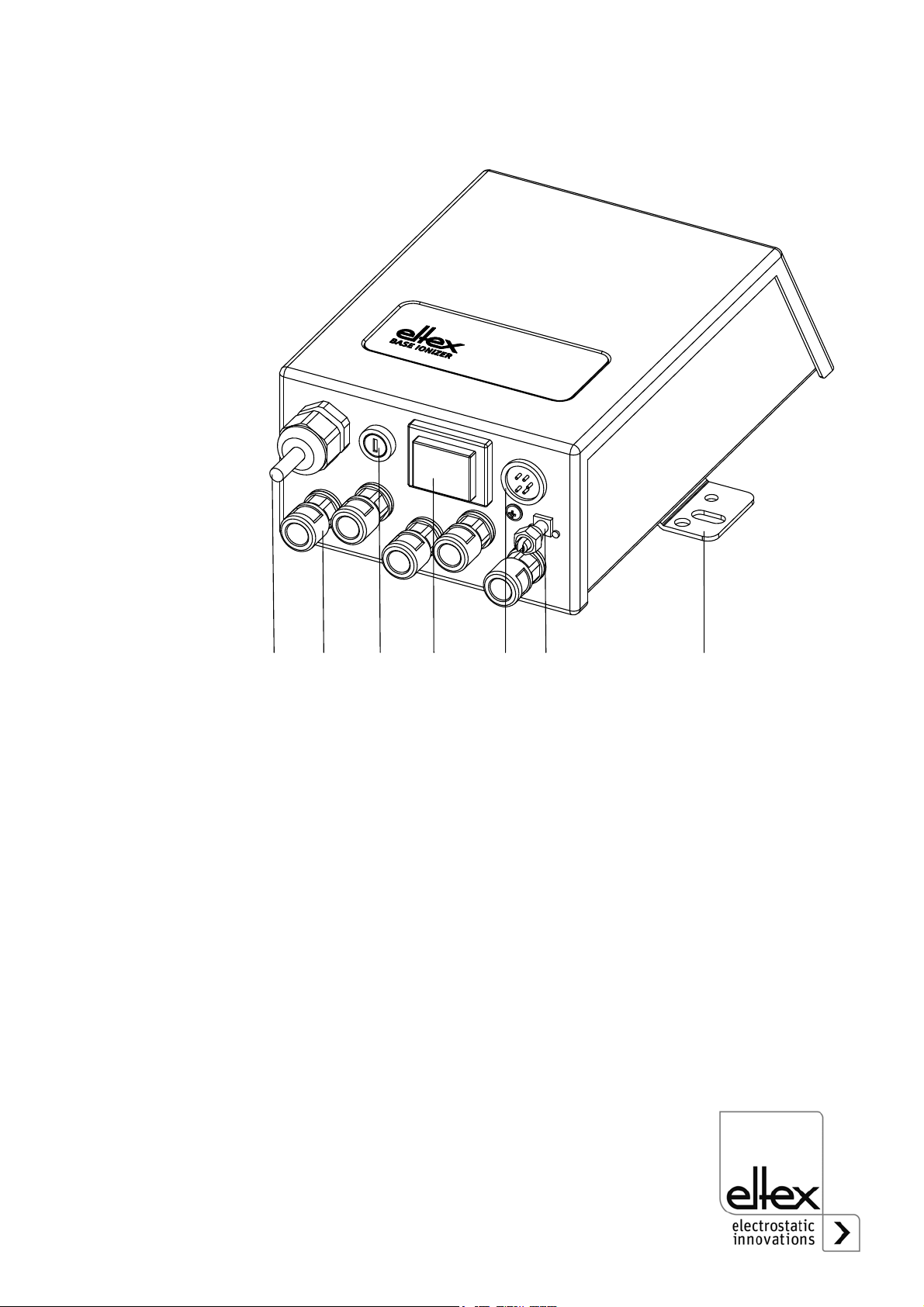
• Before starting the unit make sure that the appliance is permanently
grounded via the grounding terminal (5, Fig. 1). The ground cable
should have a minimum cross section of 1.5 mm2(see chapter 3.2
"Ground connection”, page 10).
• Check the power supplies and the discharging bars at regular intervals
for any damage to the electrical wiring and the high voltage cables. Any
damaged components must be repaired or replaced before continuing
to operate the units.
• If the housing cover is removed and the supply voltage is switched on
at the same time, contact protection is no longer effective. Always dis-
connect the power before opening the power supply units.
• The protection class IP54 only applies if the housing cover is closed
and the cable connections are shrouded.
• Connect/disconnect the discharging bars only if the power supply unit is
switched off (see chapter 3.4 "Connecting the high voltage cable”,
page 10).
• In applications involving moving bars, the high voltage cable must be
attached such that there is no cable movement near the connection
zone of the power supply unit (see chapter 3.4 "Connecting the high
voltage cable”, page 10).
• Both the lengths of the high voltage cable and of the active bars are
limited, observe maximum lengths (see chapter 3.5 "Maximum active
bar length and length of the high voltage cable”, page 11).
•To ensure that no voltage is supplied to the bars when the material web
is at rest, enabling the supply voltage to the power supply via machine
contact is recommended. If the material web is at rest, or if the machine
is not in operation, no high voltage is supplied to the bars in this case
(see chapter 3.6 "Connecting the supply voltage”, page 12).
•Before starting up the power supply the user must make sure that the
power supply and the bars have been installed and assembled cor-
rectly. The supply voltage can then be switched on (see chapter 4.1
"Startup”, page 13).

8BA-en-2088-2207_ES60
• The power supply must be checked regularly to ensure its proper func-
tioning. The connections of the high voltage cables must be free of dirt
and other foreign matter (see chapter 5.1 "Power supply”, page 14).
• Make sure that the bars are clean at all times. Dirt results in malfunc-
tions and in premature wear of the units.
• When cleaning do not soak the bars and the high voltage cable in sol-
vent and do not damage the emission tips; allow the solvent to evapo-
rate completely before restarting the unit (see chapter 5 "Maintenance”,
page 14, chapter 6 "Trouble-shooting”, page 15).
• Potential risk for wearers of cardiac pacemakers:
Moving the chest closer than 3.5 cm to the emission tips of the
discharging bars or making surface contact with several emission tips
(touching a single tip is not critical) can result in a temporary switchover
of the cardiac pacemaker into the fault mode. Permanent proximity or
contact can therefore cause severe problems.
If it is likely that the chest of such a person comes closer than 3.5 cm to
the emission tips of the discharging bar, or if several emission tips are
touched at the same time, the appropriate warning notices must be
displayed.
• The operation of the bars can generate ozone. The ozone concentra-
tion levels developing near the bars depend on many different factors
such as site of installation, bar current and voltage, air circulation, etc.,
and can therefore not be specified in general terms. If the maximum
allowable concentration of ozone must be observed at the site of instal-
lation of the bar, the concentration must be measured on site.
The AGW value (maximum admissible concentration) serves to assess
the ozone concentration at the workplace. The user must make sure
that the appropriate national AGW value is at no times exceeded, e.g.
in Germany the ozone concentration occurring during the operation of
the system must not exceed the recommended value based on interna-
tional limits of 0.06 ml/m³ (0.12 mg/m³).
2.4 Technical advance
The manufacturer reserves the right to make changes to the technical
specifications without prior notice in order to adapt the units to state-of-
the-art engineering. Eltex will provide the latest information on any
changes or modifications in the operating instructions on request.

BA-en-2088-2207_ES60 9
3. Installation and assembly
3.1 Assembling the power supply
The power supply is designed for wall mounting. Attach using the brackets
provided (installation dimensions, see Fig. 2). The operating elements of
the power supply and the terminals must be freely accessible at all times
and the display LEDs must be visible.
Z-118094y_2
Fig. 2:
Dimensions, ES60 Power Supply

10 BA-en-2088-2207_ES60
3.2 Ground connection
A permanent ground connection must be made via the grounding terminal
(5, Fig. 1). The ground cable should have a minimum cross section of
1.5 mm2.
3.3 Discharging bars, ion blower nozzles, ion blower pistols and
distributors suitable for connection
Eltex discharging bars for AC operation as well as the ion blower nozzles,
ion blower pistols and distributors can be connected to the ES60 power
supplies, each with a permanently connected high voltage cable.
3.4 Connecting the high voltage cable
Warning!
Connect or disconnect the high voltage cables only with the power supply
switched off!
Connect the discharging bars to the power supply using the prefabricated
high voltage cable. Push the high voltage cables into the sockets up to the
stop. Then secure the adapter in the socket with the clip provided (see
Fig. 3).
Cables without flexible tube and cables with plug-type adapters are
plugged in flush and secured with the clip.
Warning!
In applications involving moving bars, the high voltage cable must be
attached such that there is no cable movement near the connection zone
of the power supply unit.
Fig. 3:
Connecting the
high voltage cable
Z00004y

BA-en-2088-2207_ES60 11
3.5 Maximum active bar length and length of the high voltage cable
Both the lengths of the high voltage cable and of the active bars are
limited. The shielded high voltage cables cause a capacitive load on the
transformer inside the power supply. The maximum loading capacity is a
result of the function of the total active bar length and the total length of all
high voltage cables. Fig. 4 demonstrates this principle for R5x bars, ion
blower nozzles R36E, ion blower heads R55E and ion bower pistols PR36
and PR55.
Example: The maximum permissible total cable length with a 3 meter
active bar length is 32 meters.
Fig. 5 demonstrates this principle for R47 and R6x bars.
Fig. 4:
Loading capacity
of the Power
Supply as factor of
bar length and
length of high
voltage cable of
R5x bars, R36E,
R55E, PR36,
PR55
Z00050e
Σlengths of h.v. cable [m]
Σlengths of active bars [m]
7.5
5.0
2.5
5 10 15 20 25
permissible
range
Fig. 5:
Loading capacity
of the Power
Supply as factor of
bar length and
length of high
voltage cable of
R47 and R6x bars
Z01162d
Σlengths of h.v. cable [m]
Σlengths of active bars [m]
10
5
10 20 30 40 50
permissible
range

12 BA-en-2088-2207_ES60
3.6 Connecting the supply voltage
Connect the supply voltage via the power supply lead (1, Fig. 1) using an
earthing pin plug (depending on cable version).
To ensure that no voltage is supplied to the bars when the material web is
at rest, enabling the supply voltage to the power supply via machine con-
tact is recommended. If the material web is at rest, or if the machine is not
in operation, no high voltage is supplied to the bars in this case.
For external security of the power supply the following circuit breaker is re-
commended: Tripping Characteristic 2A/K according to DIN EN 60947-2.
3.7 Connecting the function signal
The 5-pin connecting plug (Fig. 6) is only provided in units equipped with
function monitoring. The following signals can be picked up at this plug:
• Output voltage active: contact 1, 2, 5 (contact 1 and 5 closed)
Cables prefabricated at one end are available for connection to this plug
(see spare parts).
Fig. 6:
Assignment of the
plug for function
signals
(contacts at rest)
Z01168y
12
3
4
5
2
1
5
4
3

BA-en-2088-2207_ES60 13
4. Operation
4.1 Startup
Before starting up the power supply the user must make sure that the
power supply and the bars have been installed and assembled correctly.
The supply voltage can then be switched on.
Use the toggle switch (4, Fig. 1) to switch on the power supply. In the ON
position the switch lights up green. High voltage is now supplied to the dis-
charging bars.
The output voltage is now a constant 5 kV AC.
If the fuse is defective, the switch will not light up.
4.2 Operating mode with conductive substrats
If electrically conductive substrates or substrates coated with conductive
material (e.g. metal foil or metal composites) are used, the mains supply
must be interrupted. The connected bars discharge the substrates like this
in passive operating mode.
Check for correct ground connection!

14 BA-en-2088-2207_ES60
5. Maintenance
Warning!
Electric shock hazard!
• Switch the power supply off and disconnect the supply voltage before
carrying out any maintenance or repair work.
• The machine which has the units fitted must not be in operation.
• Any work involving the units must be carried out by qualified electrici-
ans.
5.1 Power supply
The power supply must be checked regularly to ensure its proper func-
tioning. The connections of the high voltage cables must be free of dirt
and other foreign matter. The intervals for the check depend on the appli-
cation and must hence be defined by the user according to the operating
conditions. The power supply itself does not require any maintenance.
Check for correct ground connection!
5.2 Discharging bars
To ensure the trouble-free function of the discharging bars, clean the bars
at least once a week with compressed air free of oil and water (max. 6 x
105 Pa and standard compressed air pistol) and a brush with soft plastic
bristles (article RBR22, see chapter 9 "Spare parts and accessories”,
page 18). Refer to the operating instructions for the bar used.
Dirt deposits settling on the bars (e.g. grease) must be cleaned off using a
suitable solvent (benzine). Do not soak the bars and the high voltage
cable in solvent!
Caution!
Risk of deflagration!
Allow the solvent to evaporate completely before restarting the unit.
Do not damage the emission tips of the bars.

BA-en-2088-2207_ES60 15
6. Trouble-shooting
Warning!
Electric shock hazard!
• Switch the power supply off and disconnect the supply voltage before
carrying out any maintenance or repair work.
• Any work involving the units must be carried out by qualified electrici-
ans.
Fault Cause Measure
No high voltage • Lamp in mains power
switch lit: transformer
defective.
• Lamp in mains power
switch fails to light:
supply voltage not
enabled or not con-
nected.
• Defective fuse.
• Inform Eltex Service.
• Check supply voltage
and connections.
Check connected
cables, cable connec-
tions and bars.
• Replace fuse.

16 BA-en-2088-2207_ES60
7. Technical specifications ES60
Input
Supply voltage 115 or 230 V AC 50/60 Hz
Power input max. 80 VA
Fuse (primary circuit) see name plate
Recommended
protection
Tripping Characteristic 2A/K according to
DIN EN 60947-2
Mains power cable depending on the unit variant, either with groun-
ding contact plug (approx. 2.5 m) or with free
end (cable length max. 99 m)
Connectivity
Operation illuminated ON / OFF switch
Interfaces optional
Output
Voltage 5 kV AC
Current max. 6,2 mA
Frequency 50/60 Hz
pluggable connections 5
Load capacity depending on bar type and length and
high voltage cable length (see chapter 3.5)
Features
Ion balance with and without parameter diode
Function monitoring optional
passive operating mode with the power supply unit switched off
Key date
Housing type sheet metal steel with wall bracket
Ground link grounding terminal on housing
Operating ambient
temperature
0...+60 °C (+32... +140 °F)
Storage temperature -20...+80 °C (-4... +176 °F)
Ambient humidity max. 80 % r.h., non-dewing
Protection class IP54 according to EN 60529
Housing dimensions 230 x 180 x 82 mm [LxBxH]
Weight approx. 4 kg
as shown on
appliance
marking:

BA-en-2088-2207_ES60 17
8. Dimensions
Z-118096y_2
Fig. 7:
Dimensions ES60 Power Supply

18 BA-en-2088-2207_ES60
9. Spare parts and accessories
Please specify the article number when ordering.
Article Article No.
High voltage distributor discharging , 5 terminals
(1 high voltage cable, 4 outputs)
specify plug and cable length
High voltage distributor discharging, 2 terminals
(1 high voltage cable, 2 outputs)
(specify plug and cable length)
Extenxion cable
Plug "L"
Set for prefabricating the high voltage cable with flexible
tube for power supply ES60
Plug "S"
Set for prefabricating the high voltage cable without flexible
tube for power supply ES60
Flexible tube for high voltage cable (specify length)
Blanking plug for high voltage connection
Mains cable gland
Grounding terminal
ES60:
Fuse F1 (115 V) 1,25 A T (IEC 60127-2/5)
Fuse F1 (230 V) 0,63 A T (IEC 60127-2/5)
Round plug connector 5-pole for function signal
Blanking plug for function plug
Signal cable assembled (specify cable length)
Cleaning brush with handle
Operating Instructions (specify language)
ESV61/_ _
ESVY61/_ _
KE/LB
103289
101366
MCH02438
102742
MCH02176
ELM00202
113522
113211
ELM01144
ELM01115
KS/C _ _ _ _
RBR22
BA-xx-2088

EU-Declaration of Conformity
CE-2088-en-2205
EItex-EIektrostatik-GeselIschaft mbH
Blauenstraße 67 - 69
D-79576 Weil am Rhein
declares in its sole responsibility that the product
Power Supply Type ES50 / ES51 / ES53 / ES60 (according to Eltex reference code)
complies with the following directives and standards.
Relevant EU-Directive:
2014/35/EU
Harmonized standard applied:
EN 60204-1:2018
Relevant EU-Directive:
201 4/30/EU
Harmonized standards applied:
EN 55011 :2016 + A1 :2017
+ AII :2020 + A2:2021
EN IEC 61000-3-2:2019
EN 61000-3-3:2013 + A1 :2fü 9
EN IEC 61 000-6-2:2019
Low Voltage Directive
Safety of machinery - Electrical equipment of machines -
General requirements
EMC Directive
Industrial, scientific and medical equipment -
Radio-frequency disturbance characteristics - Limits and methods
of measurement
Electromagnetic compatibility (EMC) - Limits - Limit for harmonic
current emissions (equipment input current S 16 A per phase)
Electromagnetic compatibility (EMC) - Limits - Limitation of voltage
changes, voltage fluctuations and flicker in public low-voltage supply
systems, for equipment with rated current < 16 A per phase and not
subject to conditional connection
Electromagnetic compatibility (EMC) - Generic standards -
Immunity for industrial environments
Relevant EU-Directive:
2011/65/EU RoHS Directive
in the version effective at the time of delivery.
EItex-EIektrostatik-GeselIschaft mbH keep the following documents for inspection:
- proper operating instructions
- plans
- other technical documentation
Weil am Rhein, 16.05.2022
Place/Date Hahne, ing Director

Eltex-Elektrostatik-Gesellschaft mbH
Blauenstraße 67-69
79576 Weil am Rhein | Germany
Phone +49 (0) 7621 7905-422
eMail [email protected]
Internet www.eltex.de
Eltex offices
and agencies
The addresses of all
Eltex agencies can be
found on our website at
www.eltex.de
Z01007y
Table of contents