Static Clean 4203UC User manual

1
4203UC ULTRA-COMPACT
24 V DC IONIZER
WITH INTEGRATED REMOTE MONITOR

2
Static Clean static control equipment has been designed to give you many years of productive service.
However, the science of static control has unique rules which must be followed to allow the equipment to give a
good return on your investment.
Please read the following operating and maintenance instructions carefully.
Contents Page
1 Introduction 2
2 Checking on Delivered Equipment 3
3 Safety 3
4 Electrical Connections 4
5 Monitoring: LED and Remote 6
6 Commissioning and Operations 6
7 Maintenance 6
8 Troubleshooting 7
9 Accessories 8
10 Appendix I: Technical Specifications and Dimensions 9
11 Appendix II: Remote Interface and Wiring Examples 11
1.
Introduction
The Static Clean 4203UC Ultra-Compact 24V DC Ionizer is part of a high-performance range of static
eliminators from Static Clean. These products are used by leading manufacturers throughout the world to
increase safety and productivity.
Before you install the Ionizer, please follow the installation instructions carefully for maximum benefit.
1.1.
Features & Benefits
The Static Clean 4203UC Ultra-Compact 24V DC Ionizer is designed to neutralize electrostatically
charged surfaces and small products.
The use of Pulsed DC high voltage provides excellent charge decay performance even at longer
distances, and ion balance suitable for most industrial applications.
Powered by 24 V DC, it features integrated high voltage supplies meaning that no high voltage
cabling is required.
The status of the 4203UC Ultra-Compact Ionizer, including need for cleaning, is indicated by a
single LED. An ‘ATTENTION’ output signal and a ‘STANDBY’ input signal enable integration with
control system/PLC.
The 24 V DC power supply and remote signaling connections are made via an M8 4 pin
connector. An external AC-DC PSU can be ordered if 24 V DC is not available.

3
Mounting onto the machine is achieved with fixing holes integrated into the product body. Can be
combined with air nozzles for cleaning functions.
The 4203UC Ultra-Compact Ionizer is intended for use in indoor factory environments only. It is
not suitable for outdoor use.
1.2. Explanation of Symbols
Warning!
This symbol appearing in the operating instructions refers to operations which, if carried out
improperly, may result in serious personal injuries.
Caution!
This symbol appearing in the operating instructions refers to operations which, if carried out
improperly may result in damage to property.
2.
Checking On Delivered Equipment
Before starting the installation please check that the 4203UC Ultra-Compact Ionizer has not been damaged
in transit. If the packaging material is damaged, please report this immediately to the vendor.
Check that the additional items are present with the Ionizer:
Power Supply Cable
If ordered, a 24 V power supply cable with an M8 x 4 pin connector will be
supplied.
See Section 9 for details of cables and other accessories.
AC-DC Power Supply Unit
If ordered, a 24 V DC output, 100-250 V AC input PSU (Part No. 4203-31101)
will be supplied. The 0 V output is earthed and a secondary safety earth
connection is provided.
IMPORTANT: DO NOT USE standard ‘computer style’ PSUs without
earthed outputs to avoid risk of operator shocks and damage to the PSU or
Ionizer.
3.
Safety
The Static Clean 4203UC Ultra-Compact 24V DC Ionizer has been designed in accordance with the safety
requirements of EN 62368-1:2014. This IEC-derived standard is harmonized under the EU Low Voltage
Directive.

4
Warnings:
The product should be cleaned regularly. The product should not be cleaned whilst powered.
The emitter pins are a Class 1 electrical energy source, as defined in EN 62368 1:2014.
Direct contact with the emitter whilst the product is powered will not result in electrically-
caused injury, but may cause a detectable sensation due to the small current which will flow.
The emitter pins are necessarily sharp. The emitter pins are a Class 2 mechanical energy
source, as defined in EN 62368 1:2014. Contact with the emitters during cleaning may be
painful, but will not cause an injury requiring emergency medical attention.
Installation and maintenance must only be carried out by suitably qualified personnel.
The negative pole of the 24 V DC supply provided to the product must be permanently earthed.
A secondary earth connection be made to the optional air nozzle, if fitted.
Adequate installation earth / ground is required to ensure safe and proper operation.
Do not connect or disconnect the M8 cable from the Ionizer whilst it is powered.
A small amount of ozone will be produced as part of the ionization process. When installed
correctly the level of concentration of ozone is less than 0.1 ppm and is within internationally
accepted limits.
4.
Electrical Connections
4.1.
M8 Pin Assignments
The M8 connector pin numbering scheme is shown below. Note that due to the STANDBY input, this
numbering scheme differs from other Static Clean products, such as the 4203 & 4103 Bars.
The pin assignment and typical wire colors are given in the table below. This refers to cables supplied
by Static Clean. Other cables may have different color schemes.
Pin
Wire
Color
Function
Details
1
Brown
+ 24 V
21 –27 V operating range, 0.25 A maximum current.
2
White
STANDBY
Input Signal
Applying a voltage of between +21V and +27V causes the product
to enter STANDBY mode, in which the high voltage output is
disabled and the LED flashes red. Either leave disconnected or
connect to 0V if not required. 5 kΩ nominal input impedance.

5
3
Blue
0 V + GND
0 V must be connected to ground.
4
Black
ATTENTION
Output Signal
+24 V nominal output voltage, 3 kΩ output impedance in active
state. Low impedance connection to 0 V in inactive state.
4.2.
Power Supply Connections
The diagram below shows the power supply connection requirements when using the 24 V DC power
supply on the customer’s machinery.
The 24 V supply connection (Pin 1, brown wire) must be fitted with a 1 A fuse. It is recommended
that a type ‘T’ or ‘G’ fuse is installed.
The 0 V supply connection should be earthed. This connection should be made at the power supply
output terminal if possible.
The earthing terminal on the product
must
be connected to installation protective earth (PE).
WARNING: If the product is not properly earthed, there is a risk of the operator receiving an
electric shock from the product.
CAUTION: If the product is not earthed the residual ion balance of the product cannot be
guaranteed.

6
6. Commissioning and Operation
5. Monitoring: LED and Remote
The LED on the Ionizer indicates its status as follows:
LED Indication
Ionizer Status
Ionization
Green
OK
Active
Green / Red
Flashing
Cleaning / attention required
Active
Red
Overload, over temperature, hardware
fault, supply voltage out of range
Inactive
Red Flashing
STANDBY mode
Inactive
Not Illuminated
Ionizer not powered
Inactive
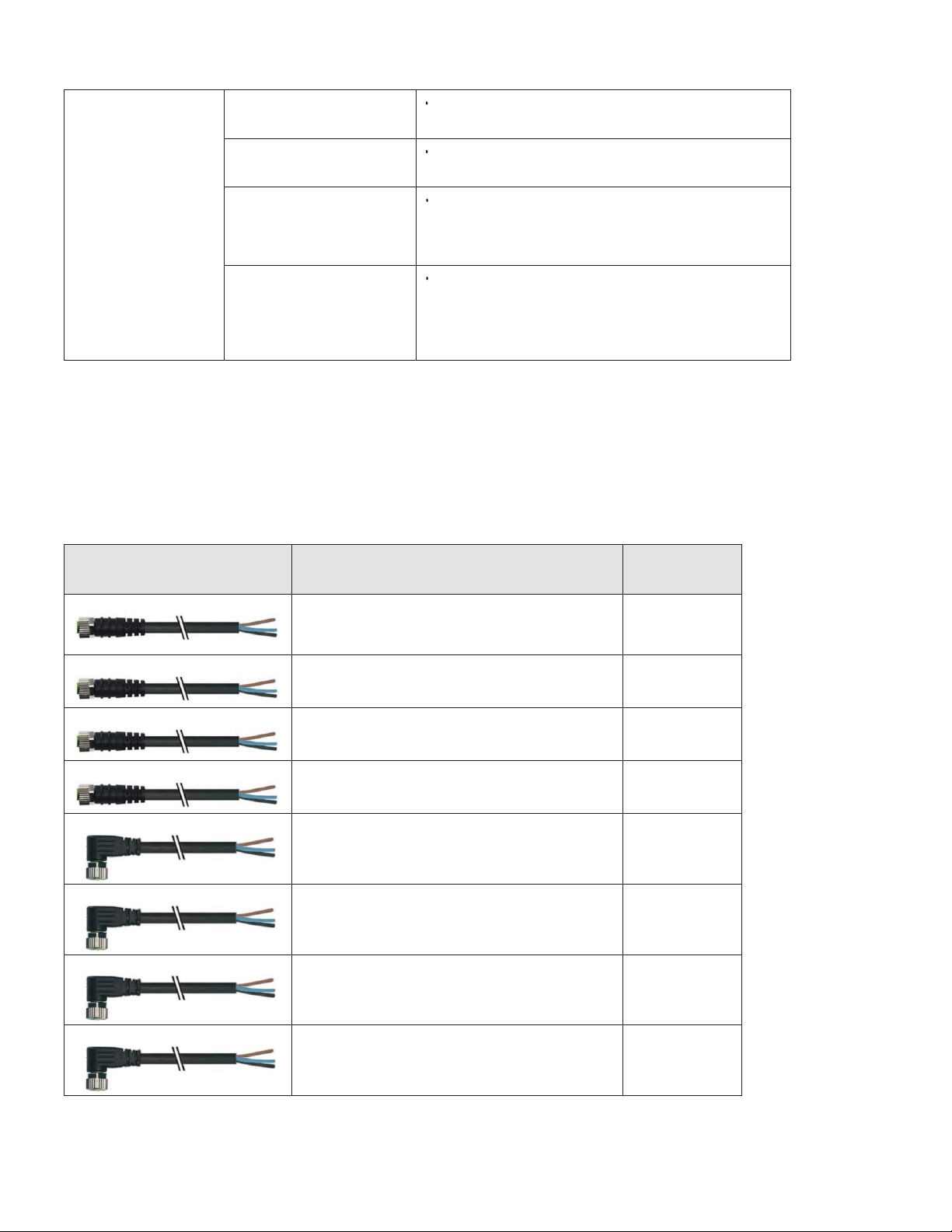
The Ionizer is equipped with a remote monitoring interface which allows the operating status of
the product to be fed into a PLC system or checked remotely.
Please see Appendix II for wiring instructions and examples for the remote monitoring interface.
Please read these instructions carefully before installing the Ionizer, because the electrical
specifications and signaling scheme of the remote monitoring interface
differ from those of
other Static Clean 24 V static eliminator products (4203 & 4103 series bars).
Before turning the Ionizer on for the first time, check:
The positioning and mounting of the Ionizer. The emitters of the Ionizer should face the product
to be neutralized, and the emitters should both be mounted a minimum of 25mm (ideally at least
50mm) from an earthed metal object. Sharp metal edges within 50mm of the emitters should be
avoided.
All metal objects, structures and surfaces in proximity to the product are earthed, such that the
proximity of the high voltage emitters does not cause these objects to become electrically
charged.
The electrical installation of the ionizer has been completed in accordance with the wiring
instructions in this document. In particular, ensure that the 0V supply return is connected to
earth.
If using the external AC-DC power adaptor, ensure that the supplementary grounding wire is
connected to the installation protective earth.
Any operators who will work in close proximity to the Ionizer are aware of its presence and
familiar with its operation.
7.
Maintenance
WARNING: Always disconnect power before working on the Ionizer.

7
Cleaning is the only maintenance required. Dirt around the emitters will reduce ionization
effectiveness and result in unsatisfactory static neutralization performance.
The frequency of cleaning will depend on the process and the environment in which the Ionizer is
installed. The Ionizer should be cleaned when an ‘ATTENTION’ state is indicated by the LED, or after
approximately 1 month of continuous operation, whichever occurs first.
To ensure best performance, the Ionizer should be visually inspected on a regular basis and cleaned
whenever convenient.
A toothbrush or soft nailbrush can be used to clean the high voltage emitters. Do not use a wire
brush as this may cause damage to the product.
Suitable cleaning materials are warm soapy water or isopropyl alcohol (IPA). The product must be
dry before the power is switched back on.
8.
Troubleshooting
In the event of problems with the product, please use the following checks:
Symptom
Cause(s)
Solution(s)
No LED
(Not Illuminated)
Product not
powered
Check power supply and connections
Check external fuse
Check supply cable for damage
Constant Red LED
Power supply voltage
outside of specified
range
Check and adjust power supply voltage
Ensure appropriate power supply cable
used
Ensure power supply not overloaded
Internal fault
Contact supplier
Flashing Red LED
Product in
STANDBY mode
Connect pin 2 of the M8 connector (usually
white wire) to 0 V, or leave disconnected.
Refer to installation instructions.
Flashing Red /
Green LED
Emitters need
cleaning
Power off product, clean emitters

8
Poor Ionization /
Neutralization
Performance
Emitters need
cleaning
Power off product, clean emitters
Emitters worn
Check emitters for excessive
wear
Ionizer installed too
far from material to
be neutralized
Review installation, move Ionizer closer to
material if possible. Refer to installation
instructions.
Emitters too close to
earthed metal surfaces
Review installation, move Ionizer further
away from earthed metal surfaces if
possible. Refer to installation instructions.
9.
Accessories
A range of accessories to assist with installation and maintenance of the Ionizer are available
from
Static Clean. Please contact your local distributor to enquire regarding
pricing and delivery of these
items.
Item
Photo
Description
Part No.
3 m cable M8 female, bare ends.
Straight socket.
4203-80892
5 m cable M8 female, bare ends.
Straight socket.
4203-80930
7.5 m cable M8 female, bare ends.
Straight socket.
4203-80931
10 m cable M8 female, bare ends.
Straight socket.
4203-80932
3 m cable M8 female, bare ends.
90° socket.
4203-80933
5 m cable M8 female, bare ends.
90° socket.
4203-80934
7.5 m cable M8 female, bare ends.
90° socket.
4203-80935
10 m cable M8 female, bare ends.
90° socket.
4203-80936

9
Universal AC/DC power supply: 100-
250V AC, 24V DC output
Fitted with 1.5m of cable.
4203-31101
2 m M8 male to M8 female 4-pin
extension cable for AC/DC power
supply unit.
4203-80937
10.
Appendix I: Technical Specification and Dimensions
Power Supply
Input Voltage:
24 V DC nominal, 21-28 V operating range
0 V earthed
Input Current:
0.25 A max
MaximumInput Power:
7 W
Input Connector:
M8, 4-pole, male
Output
Ionization Method:
Pulsed DC
Output Voltage:
+/- 7 kV nominal
Output Frequency:
10 Hz as standard
Other frequency on request from 1-50 Hz
Emitter Material:
Tungsten
Emitter Touch Current:
<100 μA (EN 62368-1:2014 ES1 source)
Monitoring
LED Status Indication:
Flashing Green: OK, Ionizer operating normally
Flashing Red / Green: Ionizer requires cleaning
Constant Red: Supply voltage out of range or internal fault
Flashing Red: Ionizer in STANDBY mode
Remote Monitor Output
Signaling Output:
‘ATTENTION’ output signal on pin 4 (black wire)
Output Signaling Levels:
24 V output, 3 kΩ output impedance
Output Current:
Sourcing (+24 V): 8 mA
Sinking (0 V): 20 mA
Limited to 50 mA max (output low) by internal protection
PLC Compatibility:
Compatible with IEC 61131-2 ‘Type 3’ PLC inputs
Remote Monitor States:
+24 V: Ionizer OK
0 V: Ionizer requires cleaning, Ionizer fault, Ionizer in STANDBY
mode

10
Remote Input
Signaling Input:
‘STANDBY’ input signal on pin 2 (white wire)
Input Signaling Levels:
0 V / 24 V nominal signal level (28 V max)
<1 V or disconnected: Ionizer operates normally
>21 V: Ionizer in STANDBY mode
Input Signaling Delay:
<1 s
Input Impedance:
5 kΩ nominal input impedance
Protection
Internal Protection:
Under-/over-voltage indication, surge protection, reverse supply
polarity protection
HVsupplies protectedagainstinternal overloadand short-circuit
Signaling output protected against short-circuit
Environmental Conditions
Ambient Temperature:
0 –55 °C
Relative Humidity
Maximum 70%, non-condensing
Ingress Protection:
IP67
Vibration:
Installation location must be vibration-free
Mechanical
Dimensions:
80mm x 47mm x 16mm (excluding connector)
Mass:
100g
Materials:
PVC body, epoxy resin encapsulant, tungsten emitter
CE Marking
EU LVD (2014/35/EU):
EN 62368-1:2014
EU EMCD (2014/30/EU):
EN 61000-6-3:2007, EN 61000-6-2:2005

11
11.
Appendix II: Remote Interface and Wiring Examples
This section describes the functioning of the remote monitoring interface in more detail and
provides wiring examples for common installation types.
11.1.
Remote Output Signaling Scheme
The remote monitoring interface has one output signal, ATTENTION. The signaling scheme is

12
described in the following table:
Condition
Ionization
Attention (Black, Pin 4)
Ionizer powered, all OK
ACTIVE (HV ON)
ACTIVE (24 V)
Ionizer powered, requires attention (e.g.
cleaning)
ACTIVE (HV ON)
INACTIVE (0 V)
Will
sink current
Overload, hardware fault, supply
voltage out of range
INACTIVE (HV OFF)
INACTIVE (0 V)
Will
sink current
Ionizer in STANDBY
INACTIVE (HV OFF)
INACTIVE (0 V)
Will
sink current
Ionizer not powered
INACTIVE (HV OFF)
INACTIVE (0 V)
Will not sink current
IMPORTANT: Because the output is implemented using an electronic switch rather than a
relay,
when the Ionizer is not powered, the output will not sink current.
11.2.
Remote Output Electrical Specifications
The ATTENTION signal is designed to allow direct connection to PLC digital inputs conforming
with IEC 61131-2 ‘Type 3’ characteristics. The detailed specification of the remote signaling
output is given in the table below.
Characteristic
Specification
Notes
High-level output voltage,
open-circuit
VIN –0.5 V
VIN is nominally 24 V. High-level output voltage
depends on power supply voltage.
Output impedance, high-level
3 kΩ
Internal pull-up to VIN
Maximum output current,
high-level, VIN = 24 V
(sourcing)
8 mA
Output shorted to 0 V
Low-level output voltage,
open-circuit
0 V
Connected internally to 0 V by low-impedance
switching device
Output impedance, low-level
<50 Ω
Maximum output
current, low-level
(sinking)
20 mA
Protected by internal self-resetting fuse
Maximum externally applied
voltage
28 V
Signal output is also protected against transient
over-voltage

13
11.3.
Remote Input Signaling Scheme
The remote interface has one input signal, STANDBY. The signaling scheme is described in the
following table:
Standby (White, Pin 2)
Ionization
LED
Low (<0.5V)
ACTIVE (HV ON)
Flashing Green
ACTIVE (HV ON)
Green / Red Flashing
INACTIVE (HV OFF)
Constant Red
High (+21V to +27V)
INACTIVE (HV OFF)
Flashing Red
11.4.
Remote Input Electrical Specifications
The STANDBY input signal is designed to allow direct connection to a PLC digital output, a switch or
a relay contact. The detailed specification of the remote signaling input is given in the table below:
Characteristic
Specificatio
n
Notes
Nominal drive voltage
0 V / 24 V
Digital input with 24 V logic-level
High-level threshold voltage
8 V typical
20 V
maximum
A high-level drive voltage of at least 21 V
is recommended
Low-level threshold voltage
6 V typical
1 V maximum
A low-level drive voltage of less than 0.5
V is recommended
Input impedance
5 kΩ +/- 10%
Internal pull-down to 0 V
Maximum input
current, input
connected to +28 V
6 mA
Limited by internal resistor
Maximum externally applied
voltage
28 V
Input is protected against transient over-
voltage. However, prolonged exposure to
voltages higher than 28 V may permanently
damage the product.
Minimum externally applied
voltage
-1 V
Drive voltages below 0 V are not
recommended. Prolonged exposure to
voltages lower than -1 V may permanently
damage the product.

14
11.5.
Remote Interface Schematic
The simplified schematic diagram below shows the implementation of the remote signaling input and
output on the Ionizer. This is a simplified model of the electronic interface within the Ionizer.
The switch in the diagram above is shown in the position corresponding to ‘Ionizer powered, all OK’.
11.6.
Interfacing with PLC Systems
To interface the Ionizer with a PLC digital input conforming with IEC 61131-2 ‘Type 3’ characteristics,
simply connect the ‘ATTENTION’ output from the Ionizer to the PLC digital input module as shown
below. The ‘STANDBY’ line may be driven directly from a 24 V digital output.
To interface the Ionizer with a PLC system having IEC 61131-2 ‘Type 1’ or ‘Type 2’ input
characteristics, fit an external 1 kΩ pull-up resistor to supply the current required by these input
types, as shown below. The resistor should have a power rating of at least 1 W.

15
11.7.
Powering the Ionizer directly from a PLC digital output
A typical 24 V, 0.5 A PLC output is capable of supplying the average current required by the Ionizer, and
can be used to power the Ionizer directly.
It is possible that over-current trips may be experienced on PLC outputs due to the pulsing of the HV
supplies in the Ionizer. This will depend on the characteristics of the PLC output module. In this
case, use the PLC output to control a relay which switches the main 24 V supply to the Ionizer.
11.8.
Connecting an external indicator to the ATTENTION output
Typical 24 V LED-based industrial indicators with rated current of 20 mA or less can be driven by
the remote signaling output. The recommended wiring scheme for an external indicator is shown
below. The indicator will illuminate when the Ionizer signals an ‘ATTENTION’ state.
IMPORTANT: Connecting indicators with higher current requirements to the Ionizer will
not
damage it, but it is unlikely that satisfactory brightness will be obtained.
11.9.
Connecting an external relay to the ATTENTION output
Toprovide potential-free contacts or switch a higher voltage or current level, a relay can be
installed between the Ionizer and external control circuit.
External relays must be connected with the Ionizer output sinking current to energize the relay coil.
PLC interfacing relays with high-sensitivity 24 V DC coils should be used to interface with the
Ionizer. Some examples are:
Phoenix Contact PLC-RSCseries
Finder 38 series
Wieland FLARE-24DC series
Omron G2RV series

16
4203UC Ultra-Compact_OI_Iss.1-EN
IMPORTANT: Relay coil drive current at 24 V should not exceed 20 mA.
IMPORTANT: The external relay should be fitted with a coil suppressor.
The recommended wiring scheme for an external relay (using an SPCO relay) is shown below.
11.10 Controlling the standby line from a switch or relay contact
The recommended wiring scheme for controlling the Ionizer from an external switch or relay
contact is shown below. When the switch or relay contact is closed, the Ionizer is in STANDBY
mode. When the switch is open, the Ionizer is active.
Table of contents