ALKOTA 3102 Series Setup guide

P.O. Box 288 105 Broad Street Alcester, SD 57001
800.255.6823 www.alkota.com
OLD VALUES. NEW IDEAS.
3102

MODEL 3102
SPECIFICATIONS
05-19-05 Z08-00036S
MACHINE SPECIFICATIONS
DISCHARGE VOLUME......................................3.0 GPM / 11.4 LPM
PUMP HEAD PRESSURE...................................1000 PSI / 69 BAR
TEMPERATURE RISE..........140°F @ 3.0 GPM / 59°C @ 11.4 LPM
COMBUSTION SMOKE/BACHARACH SCALE..#1 OR #2 SMOKE
CARBON MONOXIDE ALLOWED.......................................... 0.01%
DRAFT/STACK INSTALLATION........... 0.2” - 0.04” WC READING
HEAT INPUT............................268,800 BTU/HR / 67,738 KCAL/HR
MINIMUM INLET WATER PRESSURE................40 PSI / 0.68 BAR
FUEL TANK CAPACITY........................................... 12 GAL / 45 L
WEIGHT (DRY) ....................................................400LBS / 181 KG
HOSE, UNLOADER TO COIL..........................................Y01-00024
SPRAY TIP......................................(#7.0-15DEG) P/N J00-01507-1
HOSE, PULSE - 3/8 X 16 1/2”................................. P/N Y01-00051
BELT - MOTOR TO PUMP....................................... P/N R02-00026
HOSE, DISCHARGE............................3/8” X 50’ P/N K02-03150E1
WAND & TRIGGER GUN 42”............................... P/N J06-00158-B
HOSE, DISCHARGE (STEAM) ........ 3/8” X 50’ P/N K02-03150-1C
WAND (STEAM 42”) ............................................. P/N 120-00700A
IMPACT NOZZLE (STEAM) ..................................... P/N J05-00349
COIL w/SS WRAP ................................... 18” O.D. X 1/2”ID X 158’
SCHEDULE 40 ......................... P/N 2102-00200
COIL BACK PRESSURE (NEW)
..................5 PSI @ 3.0 GPM / 0.34 BAR @ 11.4 LPM
COIL BACK PRESSURE REQUIRING DESCALING
........................ 50 PSI @ 3.0 GPM / 3.40 @ 11.4 LPM
PUMP ........................................................................P/N N07-00002
PUMP PULLEY..............................................................R03-00646-1
PUMP PULLEY BUSHING...............................................R04-00001
PUMP TYPE..............GENERAL CERMAIC PLUNGER, OIL BATH
UNLOADER.............................................................. P/N C07-02000
MOTOR HORSEPOWER......................................... 2.0 HP / 1.5 KW
MOTOR SPEED……………...............................................1750 RPM
MOTOR VOLTAGE.......................................115V / 230V 60HZ 1PH
MOTOR PART NUMBER................................................. F02-00053
MOTOR PULLEY...................................................... P/N R03-00339
MACHINE VOLTAGE.............................................. 115V 60HZ 1PH
CURRENT……......................................................... 115V 19.7 AMP
CAM SWITCH......................................................... P/N F04-00741A
POWER CORD (GFI) ............................................... P/N F04-00177
TEMP CONTROL, ADJUSTABLE (OPTIONAL)..... P/N F04-00818
BURNER ............................................................. P/N V00-173139-2
BURNER W/SOLENOID ..................................... P/N V00-173159-2
BURNER TYPE......................................... PRESSURE ATOMIZING
FUEL TYPE.....................................KEROSENE, #1 OR #2 DIESEL
FUEL PRESSURE...................................................120 PSI / 8 BAR
FUEL NOZZLE................(1.75 90DA DEGREE A) P/N V1.75 90DA
FUEL CONSUMPTION................................1.92GPHR / 7.26 LPHR
FUEL PUMP...................................(DAN FOSS) P/N V-100714-001
MOTOR HORSEPOWER.........................................................1/7 HP
MOTOR SPEED.................................................................3450 RPM
PUMP & UNLOADER
PUMP MOTOR
ELECTRICAL
PERFORMANCE
GENERAL
BURNER

SERIAL NUMBER DATE OF
PURCHASE PLACE OF PURCHASE
MONTH / DAY / YEAR OPERATING
HOURS MAINTENANCE PERFORMED
MACHINE RECORD
Supersedes 01-08-04 Z08-04527 08-25-04 Z08-04527
NOTES

OPERATION - TABLE OF CONTENTS
OPERATION TABLE OF CONTENTS
ELECTRIC MOTOR DRIVEN CLEANERS
Supersedes 09-17-03 Z08-03937 08-23-04 Z08-03937
2
SAFETY INSTRUCTIONS
Page Number
•Safety Symbols 2
•General 3
•Mechanical 3
•Electrical 3
•Fuel 3
INSTALLATION
•Location 4
•Electrical 4
•Extension Cord 4
•Venting 4
•Water Supply 5
•Barrier 5
•WaterConditions 5
•Freezing 5
•Coldweather 5
•Chemicals 5
VENTING
•DraftDiverters 5
•VentingInstallation Information 6
OPERATION
•PreStart-Up 6
•Start-Up 6
•ToClean,Apply Chemical, To Rinse 7
•Shut Down 7
(OPTIONAL) COMBI OPERATION
•PreStart-Up 8
•Start-Up 9
•ToClean,Apply Chemical, To Rinse 9
•Shut Down 9
MAINTENANCE
Machine
•SprayTipMaintenance 10
•BeltTension 10
•Coil Back Pressure 10
•Schedule 12
•Flushing,Storage 11
Burner
•Fuel Pump Screen See Parts List Section
•TransformerCheck See Parts List Section
•BurnerGunRemove/Replace See Parts List Section
•BlowerFanRemove/Replace See Parts List Section
Fuel Filter
•Maintenance See Parts List Section
TROUBLESHOOTINGPage Number
•Machine 13,14
•WaterHeater 15
•OilBurner See Parts List Section
•Pump See Parts List Section
•Fuel Filter See Parts List Section
SERVICE
•Pump See Parts List Section
•Fuel Filter See Parts List Section
•TriggerGun See Parts List Section
•Unloader See Parts List Section
COMPONENT ADJUSTMENT
Burner
•Air BandAdjustment See Parts List Section
•Buss Bar Alignment
See Parts List Section
•Electrode Ass’y Adjustment
See Parts List Section
Chemical Metering Valve See Parts List Section
Temperature Control (If So Equipped)
See Parts List Section
Unloader Valve See Parts List Section
PUMP OIL CHANGE
RECORD See Parts List Section
WARRANTY InsideBack Cover
SPECIFICATIONS InsideFrontCover

SAFETY, INSTALLATION, AND OPERATION
ELECTRIC DRIVEN OIL FIRED CLEANER
08-19-04 Z08-02830
MACHINE UNPACKING
ALL CLEANERS ARE CAREFULLY INSPECTED AND
CARTONED TO PROTECT AGAINST SHIPPING
DAMAGE. IFTHERE ISDAMAGEORMISSINGPARTS,
THETRANSPORTATION COMPANYAGENTSHOULD
MAKEA NOTATION TO THAT EFFECT ON THE BILL.
REFER TO THE PARTS LIST IN THIS MANUAL AND
ADVISE WHAT PARTS AREMISSING ORDAMAGED.
IFAVAILABLE, GIVE THE INVOICE NUMBER ONALL
ORDER BILLS. THIS PROCEDURE WILL ENABLE
NEEDEDPARTSTOBE SHIPPED QUICKLY.
READ ALL Installation, Operation, and Maintenance
instructionsbeforeoperating the machine
NOTE:RefertoCLEANERMODELforSERIALNUMBER
location
NOTE: Dimensionsare in inches unlessotherwisenote
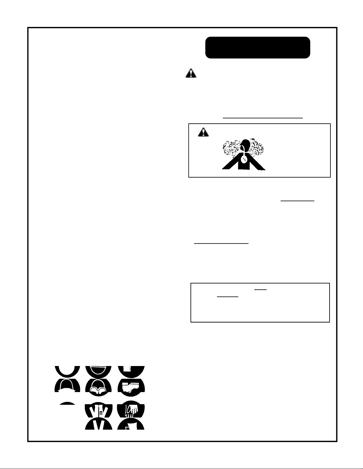
The safety alert symbol.
This symbol is used to identify safety information about
hazards that can result in personal injury.
Asignalword(DANGER,WARNING,orCAUTION)isused
with the alert symbol to indicate the likelihood and the
potential severity of injury. In addition, a hazard symbol
may be used to represent the type of hazard
DANGER indicates a hazard which, if not avoided,
will result in death or serious injury.
WARNING indicates a hazard which, if not avoided,
could result in death or serious injury.
CAUTION indicates a hazard which, if not avoided,
might result in minor or moderate injury.
CAUTION, when used without the alert symbol,
indicates a situation that could result in damage to
the equipment.
1. Before operating this machine, read and observe all
safety,unpacking, and operatinginstructions. Failure
to comply with these instructions could create a
hazardous situation.
2.Theoperatorofthisequipment should not operate this
equipmentwhenfatiguedor underinfluenceofalcohol
ordrugs.
3. The operator of this equipment should be thoroughly
familiar with its operation and trained in the job to be
accomplished.
4.Theoperatorofthis equipment should wear protective
faceshieldsandotherprotectiveclothingasrequired
forsafeoperation.
5. Keep all protective covers and shields in place.
Operatingthismachine withmovingpartscould allow
operatoror bystander serious injury orevendeath.
6. Do not operate the machine if any mechanical failure
is noted or suspected. Keep all shields in place.
7. Do not leave this machine unattended when it is
operating.
8. All installations must conform to all applicable local
codes. Contact your electrician, plumber, utility
company or seller for details.
9. If a water leak is found, DO NOT OPERATE THE
MACHINE. Shut off the motor and repair.
10. Follow instructions on how to stop the machine and
bleed pressures quickly. Be thoroughly familiar with
the controls.
11 ..When starting a job, survey the area for possible
hazardsandcorrect before proceeding.
12 .If chemicals are used in conjunction with this
equipment, read and follow the product label
directions.
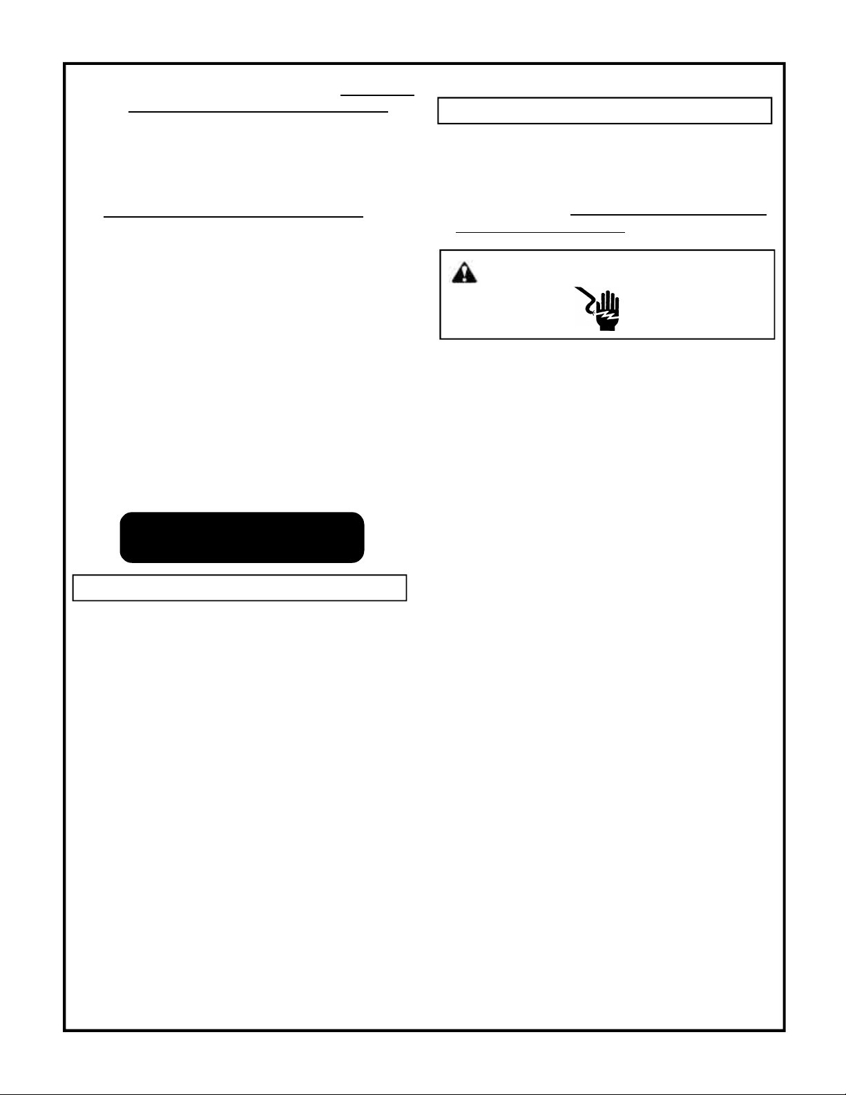
13 .During normal operation of this machine, HOT
discharges and surfaces may be produced.
14 .Always shut down machine before refueling.
15 .Do not overfill the fuel tank. If any spillage occurs,
cleanupimmediatelyand/or neutralizethespillbefore
attempting to operate the machine.
3
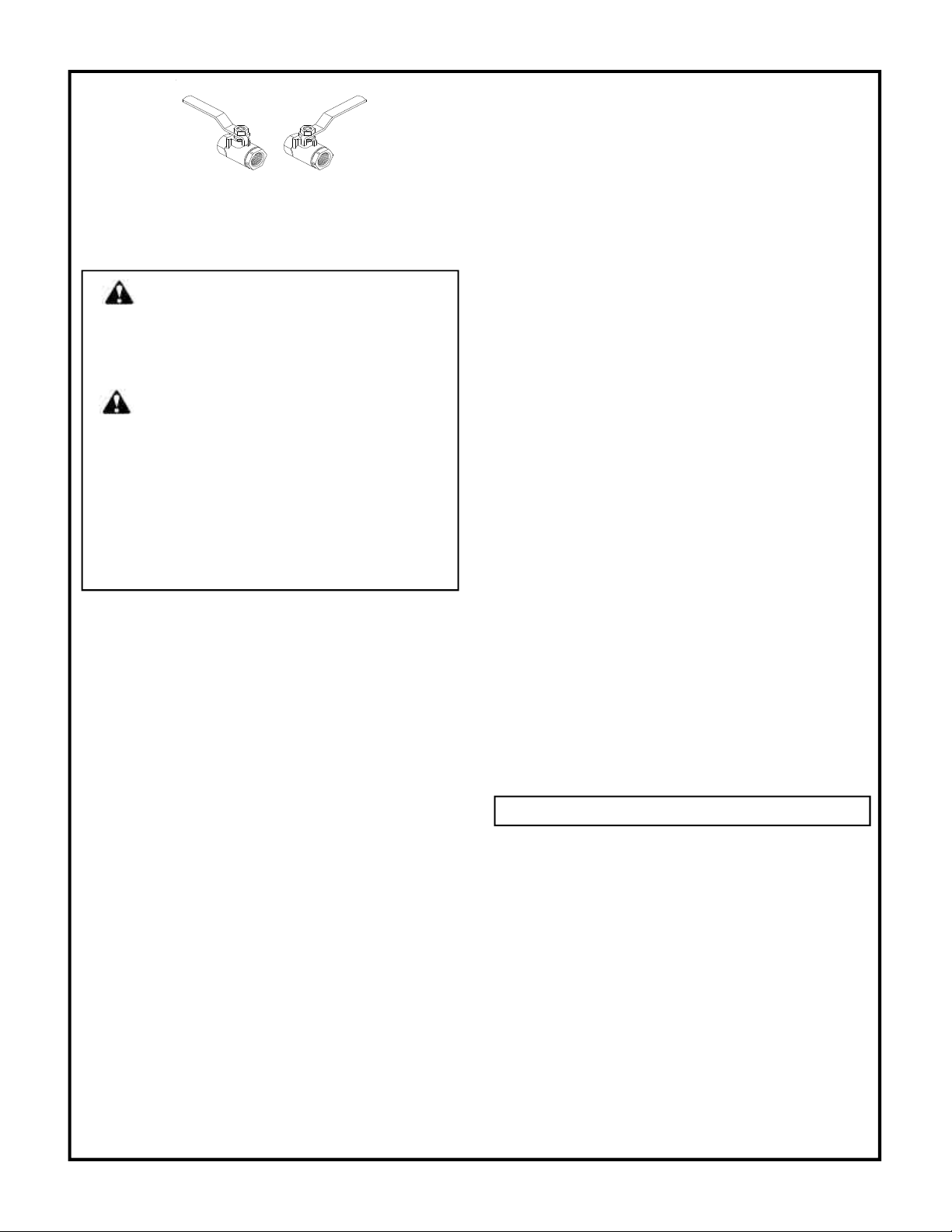
WARNING: OPENFLAME. Donot operate
this machine in an area with combustible
materials. A suitable fire extinguisher
shouldbeavailable in operating area.
IMPORTANT SAFETY
INSTRUCTIONS
GENERAL SAEFTY
Supersedes 08-15-03 Z08-02830
Read and understand this “OPERATOR’S
MANUAL” and “LABELS ON THE MA-
CHINE” before starting

08-19-04 Z08-02830A
16 .Do not start the burner unless a full flow of water is
comingfromthe wand. Air leaks or insufficient water
to the machine means less than full flow of water
through the coil. This could cause hose failure and
burnsto the operator.
17 .Donot start the machine unlessthegunassembly is
firmlygrippedby the machine operator. Failure to do
this could result in injury from flying hose and gun
assembly.
18 .Always point the gun assembly in a safe direction
and do not direct spray on the cleaner.
1.All guards, shields, and covers must be
replaced after adjustments are made
to prevent accidental contact with
hazardousparts.
2.Drivebeltsmust beinspectedandtightenedperiodically
to operate at optimum levels.
3.Inspect machinefordamagedor worncomponentsand
repair or replace to avoid potential hazards. Do not
operatethe machineifanymechanical failureisnoted
or suspected.
4. Always use the correct size spray tip specified in the
GENERALsection of theMODELSPECIFICATIONS
or MODEL EXPLODED VIEW.
1. This machine must be electrically grounded.
Failureto have the machine grounded may
result in the operator being electrically
shockedand even death.
2. Do not plug–in or un–plug machine with wet hands.
3. Keep power cords and connections (connectors) out
ofwater.
4. If an extension cord must be used to operate this
machine, it should be as short as possible. The
extensioncordmustbeproperly sized and fitted with
a grounding type plug and receptacle.
5. All wiring and electrical connections should comply
withthe NationalElectricalCode(NEC) andwithlocal
codes and practices.
6. Fuses or circuit breakers should be compatible with
machine requirements. (See ELECTRICAL section
of MODEL SPECIFICATIONS for power
requirements.)
7. High voltage may be present within this machine.
Servicing should only be performed by properly
trainedpersonnel.
1. Use only fuel #1 or #2 diesel. The use of incor-
rect fuel may result in fire or explosion and severe
injury to the operator.
2. Do not refuel machine while it is running or hot. Allow
it to cool sufficiently to prevent ignition of any spilled
fuel. Cleanup anyspilledfuel beforeresumingopera-
tion.
3. Fuel burning equipment must have proper ventilation
for cooling, combustion air, and exhausting of com-
bustionproducts.
4. Stacking, where required, must be installed in accor-
dance with all local codes. A draft diverter must be
installedon amachineconnectedto anexhauststack
topreventimproper operation.
5. Wherestackingis notrequired,provideadequate ven-
tilationstopreventanypossibleaccumulation of haz-
ardousfumes.
6. Personneltrained in andfamiliarwith the typeofequip-
mentbeing serviced shouldonlyperform adjustments
tofuelburningequipment.
SAVE THESE SAFETY
INSTRUCTIONS
4
WARNING: RISK OF INJECTION OR SEVERE
INJURY. KEEP CLEAR OF NOZZLE. DO NOT DIRECT
DISCHARGESTREAMATPERSONS.THISEQUIPMENT
IS TO BE USED ONLY BY TRAINED OPERATORS.
AVERTISSEMENT:RISQUED’INJECTION ETDE
BLESSURESGRAVES.SETENIRÀL’ÉCART DU JET.
NEPAS DIRIGER LE JET DE SOTIE VERS D’AUTRES
PERSONNES CONFIER L’UTILISATION LE JET DE
SOTIE VERS D’AUTRES PERSONNES. CONFIER
L’UTILISATION DE CE MATÉRIEL À UN OPÉRATEUR
QUALIFIÉ.
WARNING: DO NOT USE GASOLINE,
CRANKCASE DRAININGS, OR OIL
CONTAININGGASOLINE OR SOLVENTS.
AVERTISSEMENT: NE PAS UTILISER
D’ESSENCEDEPRODUITS DE VIDANGE NI
MECHANICAL SAFETY
ELECTRICAL SAFETY
FUEL SAEFTY
08-15-03 Z08-02830

08-19-04 Z08-02830B
1. LOCATION: This machine should be installed
by only qualified technicians. The machine should
be set upon a level surface where it will not be
affected by strong winds, rain, snow, extreme heat,
and freezing temperatures. Install the machine
considering locations for chemical pick-up, fuel
connections,electrical connections, water hook-up,
venting,and maintenance.
All wiring and electrical connections should
comply with the National Electrical Code (NEC) and
with local codes and practices. Use the chart on the
next page for your cord selection
2. ELECTRICAL: Connectmachine to an electrically
grounded circuit that is fused or circuit breaker
protected. The circuit must match that specified in
the ELECTRICAL section under MODEL
SPECIFICATION
3. EXTENSION CORD: The use of an extension cord
thathasundersizewire compared to the amp draw of
your machine will adversely limit the starting load
carrying abilities of the motor and machines
performance. Use only 3-wire extension cords that
have 3-prong plugs and 3-pole cord connectors that
accepttheplug fromtheproduct. Useonly extension
cords that are intended for outdoor use. These
extension cords are identified by a marking
“Acceptable for use with outdoor appliances; store
indoors while not in use.” Use only extension cords
having an electrical rating not less than the rating of
the product. Do not use damaged extension cords.
Use an extension cord in good repair free of frays or
cracksinthe outer covering. Donotabuseextension
cord and do not yank on any cord to disconnect.
Keepcordawayfromheat and sharp edges. Always
disconnect the extension cord from the receptacle
beforedisconnectingtheproductfromtheextension
cord.
COPPER
WIRE SIZE
MINIMUM
AWG
MACHINE AMP
DRAW*
3 CONDUCTOR
WIRES
MACHINE AMP
DRAW*
2 CONDUCTOR
WIRES
16 10 13
15 -- --
14 15 18
12 20 25
10 25 30
835 40
645 55
460 70
280 95
5
WARNING: ELECTRICAL SHOCK
HAZARD
WARNING: To reduce the risk of electrocution,
keep all connections dry and off the ground. Do not
touch plug with wet hands.
CHART FIGURES ARE BASED ON NOT
MORE THAN 100 FOOT
(BasedonAmbientTemperatureof 86°F (30°C)).
*UseAmp Draw indicated the same or higher than your
machineoutput
EXAMPLE: MachineAmpDraw51,use55(2Conductor).
The thermostat type of cord shall be C, PD, E, EO, EN,
S, SO, SRD, SJ, SJO, SV, SVO, SP.
The thermo set plastic types shall be ET, ETT, ETLB,
ETP,ST,STO, SRDT, SJT, SJTO, SVT, SVTO, and SPT.
4. VENTING: This machine emits carbon monoxide, a
deadlygas, andmustbe ventedifused inanenclosed
area. Improperventingcan cause poor combustion,
delayed ignition, down drafts, and the possibility of
freezing the coil. Contact your distributor or local
heating and air conditioning dealer for proper
materials. Local codes must be observed.
WARNING: CARBONMONOXIDE
HAZARD
INSTALLATION
08-15-03 Z08-02830

5. WATER SUPPLY: This machine must have a water
supplymeeting orexceedingthe maximumdischarge
volumespecifiedinthe PERFORMANCEsection,and
a minimum water inlet pressure specified in the
GENERALsectionoftheMODELSPECIFICATIONS.
6. BARRIER: We recommend a barrier be installed
between the machine and wash area to prevent
moisturefromcoming in direct contact with electrical
controls,motorsandtransformers. This will increase
the machine’s life and lessen electrical problems.
7. WATER CONDITIONS: Local water conditions affect
the coil adversely more than any other element. In
areas where troublesome conditions may exist with
like equipment (such as water heaters), we
recommendthe use of a watersoftener.
8. FREEZING: This machine must be protected from
freezingaccordingtoSTORAGEsectionofMACHINE
MAINTENANCE.
9. COLD WEATHER: As the weather becomes colder,
fuel becomes thicker and may become so viscous
that the fuel will not flow properly. As viscosity
increases,the thicker oil can causedelayedignition,
poorspraypatterns,and rumbling fires. Asmoisture
will quickly destroy fuel pumps, make certain that
tankopeningsaresecureandmoisturecannotenter.
In cold weather areas, frost build up will occur in fuel
tanks.As the weather warms it turns to condensate,
andthe water will be in thetank. Keepthe tank clear
of water, as moisture reaching the fuel pump will
cause rust, and the pump will bind. A full fuel tank
will lessen condensation build up.
10. CHEMICALS: Mix chemicals per the chemical
manufacturers printed directions. Follow all mixing,
handling, application, and disposal instructions.
Weargloves,boots,goggles,andprotectiveclothing
appropriatefor the chemical being used
WARNING: Thismachineemitscarbonmonoxide,
and deadly gas, and must be vented if used in an
enclosed area. Improper venting can cause poor
combustion, delayed ignition, down drafts, and the
possibilityof freezingthecoil. Contactyour distributor
orlocalheatingandair conditioning dealer for proper
materials. Local codes must be observed.
Theinformationcontainedhereinis offered for reference
only. You must comply with local codes and
investigate through your gas and other utility
companies when installing, as there may be some
special local requirements you must comply with.
Also seeANSI Z223.
1. DRAFT DIVERTERS:(STACKED CLEANERS)
Oilfiredmachinesuseaforceairburner.Theoilburner
canbe influencedby“NaturalDraft” eventhoughthey
havetheirown fan. A Bell type draftdivertermust be
used here also.
A. Adraftdivertermust be used on all cleaners that are
stacked. This includes any chimney even if not
expelled to the outside.
B. Usea draft diverter of the invertedfunnelorbelltype
thatmeets allcodesforcapacityandmaterials.Mount
the draft diverter directly to the stacking flange on
themachine
C. The draft diverter’s function is to insure that the
barometric pressures are as close to the same as
possible at the air inlet and outlet to the coil and will
not be changed by either up drafts or down drafts.
08-19-04 Z08-02830C
6
WARNING: CARBONMONOXIDE
HAZARD
THIS MACHINE IS NOT TO BE CONNECTED
TOA TYPE B GAS VENT.
NE PAS RACCORDER CET APPAREIL À UN
TUYAUD’ÉVACUATION DE GAZ DU TYPE B.
VENTING
08-15-03 Z08-02830

D. Installation of a draft diverter WILL NOT
PREVENT THE COIL FROM FREEZING. In
areas where freezing temperatures are
common, some type of down draft prevention
mustbeused. Checklocalcodesforacceptable
methodsforthe prevention of down drafts.
2. VENTINGINSTALLATION INFORMATION:
A. Never Reduce the Stack size. The diverter and
stacking should be the same size as the stack
openingon the machine.
B. Straight Stacking through the roof is preferred.
Horizontal runs are not desirable, but if necessary,
be sure to pitch the stack upward at a rate of two
inches per foot. When horizontal stacks are used,
vertical stacking must extend at least two feet for
every foot of horizontal stack.
C. StackExtensionabovethe rooflineshouldbesufficient
to clear the peak of the roof. (Refer toANSI Z223.1
page100ofSPECIFICS)
D. A Rain Cap U.L. approved should be installed on the
stack
1. The first time the machine is operated, after repairs
havebeenmade,orifthemachinehasset foraperiod
of time (30 days or more) follow the following
procedures.
A. Check the tension of the belt (if so equipped)
perinstructions in MACHINE MAINTENANCE.
B. Flushthe machine per instructions in MACHINE
MAINTENANCE.
C. Install float tank drain plug (if so equipped).
D. Openfloat tank ball valve(ifso equipped).
2. CAUTION: Always use the factory supplied wash
hose with your machine. Do not substitute other
hoses as a potential safety problem may develop.
CAUTION: If machine has been exposed
tosub-freezingtemperatures,it must be thoroughly
warmedto above freezing before operating. Failure
to warm machine can cause damage to the pump
packings and other components.
Read and observe all items in “CLEANER
INSTALLATION”.
♦Refer to the MAINTENANCE SCHEDULE for any
maintenance to be performed before operation
♦ELECTRICAL: Connect the machine to an
electrically grounded circuit that is fuse or circuit
breaker protected. Do not use any type of adapter.
Ifthecorrecttypeofreceptacle is not available, have
one installed by a qualified electrician.
♦OIL LEVEL: Check the oil level in the water pump.
♦BELT: Make sure belt tension and condition is as
specifiedinMACHINEMAINTENANCE.
♦STACK COVER: Remove the stack cover (if so
equipped).
♦FUEL FILTER: Inspectfuelfilterforevidenceof water
contaminants.
♦FUEL: Makesure thefuellinesare open(CAUTION:
Closed valves will DAMAGE the fuel pump and void
warranty). Use #1 or #2 diesel.
♦FUEL QUANTITY: Make sure the fuel supply is
sufficient to complete the job. See the GENERAL
sectionof MODEL SPECIFICATIONSforthefueltank
capacity.
♦WATER SUPPLY: This machine must have a water
supplymeeting orexceedingthe maximumdischarge
volumespecifiedinthe PERFORMANCEsection,and
aminimumwater inlet pressureof40PSI / 0.68BAR.
♦LIME: Water containing large amounts of lime,
calcium or other similar materials can produce a
coating on the inside of the spray tip, impact nozzle
and coil pipe.
♦FLOAT TANK: Check the float tank (if so equipped)
toassure itisfulland thefloatvalveshuts offsecurely.
08-19-04 Z08-02830D
7
WARNING: ELECTRIC SHOCK HAZARD
OPERATING
INSTRUCTIONS
PRE START-UP
START-UP
08-15-03 Z08-02830

♦FLOAT TANK BALL VALVE: Check the position of
theball valve on the outlet sideofthe float tank (if so
equipped) that it is in the open position.
1Selecttemperature(if so equipped).
2Withthe gunassemblyinhand (ontriggergun models
holdthe trigger gun valve in open position)andwith
a good flow of water turn the switch to the “pump”
position.
CAUTION:A good flow of water mustbeflowingfrom
the end of a gun for 30 seconds, before proceeding.
Lack of water can cause damage to the water pump
andlike components.
CAUTION: Ona machineequippedwitha triggergun
valve, if the trigger gun valve remains in the closed
positionfor more than3minutes,water pumpdamage
may occur.
3Turn the switch to the “burner” position.
CAUTION: Do not run the machine with the burner
switch in the on position when the fuel tank is empty
or with tank valves closed. This will cause damage
to the fuel pump and void warranty.
CAUTION: Donotoperatewiththetriggergunvalve
closedformorethan3minutesorwaterpumpdamage
may occur.
TOCLEAN:
AStartonthelowerportionoftheareatobecleaned
andworkupusinglong,even,overlappingstrokes.
BDirt is generally removed easily if grease and/or
oil are not present. However if grease and/or oil
are present, hot water and chemical will
accelerate in the cleaning process.
4TOAPPLY CHEMICAL:
CHEMICAL: Use factory recommended chemicals
for best cleaning action and for extended pump life.
Contact your dealer for chemicals available. Follow
instructions on chemical container.
Mixchemicalsperlabelinstructions. Use necessary
safetyprecautions.
A. Insert chemical screen into chemical container
B. Adjustmeteringvalve (if so equipped).
C. If the gun assembly is equipped with variable or
multiple nozzle assembly, adjust as desired.
TO RINSE:
A. Ifthemachineisequippedwith a panel mounted
meteringvalve, closethechemicalmeteringvalve
(ifsoequipped). NOTE: It is advisable to dip the
chemical screen in a container of clean water
andopenthevalve1minutetoclean the valve of
anyremaining residue.
B. If the gun assembly is equipped with variable or
multiplenozzleassembly,openandclosetoclean
nozzle of any remaining residue.
C. After a clear flow of water is noted from the end
ofthewand,startfromthetop,working downward
usinglong, overlapping strokes.
1Turn theswitch to thepump“position”. (Ifnot already
done so in the cold water rinse.)
2After cool, clear water is coming from the end of the
wand, turn switch to the “off” position .
3Turn off the water supply.
4If freezing conditions may exist, refer to STORAGE
inMACHINE MAINTENANCE.
5Replacestackcover (if so equipped).
08-19-04 Z08-02830E
8
OPEN CLOSED
BALL VALVE POSITION
WARNING: RISK OF INJECTION OR
SEVERE INJURY. KEEP CLEAR OF NOZZLE.
DO NOT DIRECT DISCHARGE STREAM AT
PERSONS. THIS EQUIPMENT IS TO BE USED
ONLY BY TRAINED OPERATORS.
AVERTISSEMENT:RISQUE D’INJECTION
ET DE BLESSURES GRAVES. SE TENIR À
L’ÉCART DU JET. NE PAS DIRIGER LE JET DE
SOTIEVERS D’AUTRESPERSONNESCONFIER
L’UTILISATION LE JET DE SOTIE VERS
D’AUTRES PERSONNES. CONFIER
L’UTILISATION DE CE MATÉRIEL À UN
OPÉRATEURQUALIFIÉ.
SHUT-DOWN
08-15-03 Z08-02830

NOTE: In process of making steam, the water flow
throughthe coil has to be decreased. Theamountof
water is determined by the pressure and water
temperature of your location.
Iftheincoming water temperature is as high as 70°F,
the amount of water going through the coil has to
decrease very little.
If the incoming water temperature is as low as 40°F,
the amount of water going through the coil has to be
decreased.
The water temperature is relative to the season
variationand should be taken inconsiderationwhen
operatingsteam.
1. Settemperature control at 300°F /150°C MAXIMUM.
2. Openthewater bypass ball valve (if so equipped) on
the coil inlet assembly.
TEMPERATURE REGULATING:
Regulate the temperature indicated on the
thermometer to 300°F by adjusting the regulating
valve.
3. Turn the tee on the regulating valve (if so equipped)
clockwise to DECREASE the temperature and
counter clockwise to INCREASE the temperature.
1. Settemperature control at 300°F /150°C MAXIMUM.
2. Completelyopenthewaterbypassmeteringvalve(if
soequipped)handleturningitcounterclockwisefound
on the pump assembly.
3. With a small common screw driver turn the screw on
themeteringvalve (ifsoequipped)counter clockwise
to DECREASE the temperature and clockwise to
INCREASEthe temperature.
08-19-04 Z08-02830F
9
WARNING: This machine should be
operated only by personnel instructed in and
familiar with its operation. The discharge
produced is 300°F / 150°C and can cause
SERIOUS BODILY INJURY to you and anyone
coming in contact with it.
COMBI OPTION
OPERATING INSTRUCTIONS
OPEN
CLOSED
DECREASE
TEMPERATURE
INCREASE
TEMPERATURE
OPEN CLOSED
BALL VALVE POSITION
WARNING: RISK OF INJECTION OR SEVERE
INJURY. KEEP CLEAR OF NOZZLE. DO NOT DIRECT
DISCHARGESTREAMATPERSONS.THISEQUIPMENT
IS TO BE USED ONLY BY TRAINED OPERATORS.
AVERTISSEMENT: RISQUED’INJECTIONETDE
BLESSURESGRAVES. SETENIRÀL’ÉCART DU
JET. NE PAS DIRIGER LE JET DE SOTIE VERS
D’AUTRESPERSONNESCONFIER L’UTILISATION LE
JET DE SOTIE VERS D’AUTRES PERSONNES.
CONFIER L’UTILISATION DE CE MATÉRIEL À UN
OPÉRATEURQUALIFIÉ.
08-15-03 Z08-02830
TEMPERATURE
DECREASE
INCREASE
TEMPERATURE
COMBINATION
PRESSURE
REGULATING
VALVE
PRESTART-UP
HIGH VOLUME COMBI
PRESTART-UP
LOW VOLUME COMBI

08-19-04 Z08-02830G
10
1. Turntheswitchtothepump “position”. (If not already
done so in the cold water rinse.)
2. After cool, clear water is coming from the end of the
wand, turn switch to the “off” position .
HIGH VOLUME COMBI:
A. Close the water bypass ball
valve (if so equipped) on the
coil inlet assembly.
LOW VOLUME COMBI:
A. Completely Close the water bypass
meteringvalve(ifsoequipped)handle
turningitclockwisefoundonthepump
assembly.
3. Install the trigger gun assembly.
4. Turn off the water supply.
5. Iffreezingconditionsmayexist,refertoSTORAGEin
MACHINEMAINTENANCE.
6. Replacestack cover (if so equipped)
SHUT-DOWN
08-15-03 Z08-02830G
1. Install the open gun assembly.
2.Withthe gun assembly in hand (on triggergunmodels
holdthe trigger gun valve in open position)andwith
a good flow of water turn the switch to the “pump”
position.
CAUTION:A good flow of water mustbeflowingfrom
the end of a gun for 30 seconds, before proceeding.
Lack of water can cause damage to the water pump
andlike components.
CAUTION: Ona machineequippedwitha triggergun
valve, if the trigger gun valve remains in the closed
positionfor more than3minutes,water pumpdamage
may occur.
3. Turn the switch to the “burner” position
CAUTION: Do not run the machine with the burner
switch in the on position when the fuel tank is empty
or with tank valves closed. This will cause damage
to the fuel pump and void warranty.
CAUTION: Donotoperatewiththetriggergunvalve
closedformorethan3minutesorwaterpumpdamage
may occur.
TOCLEAN:
A. Startonthelowerportionoftheareatobecleaned
andworkupusinglong,even,overlappingstrokes.
B. Regulate the temperature indicated on the
thermometer to 300°F by turning the regulating
valve.
TOAPPLY CHEMICAL:
CHEMICAL: Use factory recommended chemicals
for best cleaning action and for extended pump life.
Contact your dealer for chemicals available. Follow
instructions on chemical container.
Mixchemicalsperlabelinstructions. Use necessary
safetyprecautions.
A. Insert chemical screen into chemical container
B. Adjustmeteringvalve (if so equipped).
C. If the gun assembly is equipped with variable or
multiple nozzle assembly, adjust as desired.
TO RINSE:
A. Ifthemachineisequippedwith a panel mounted
meteringvalve, closethechemicalmeteringvalve
(ifsoequipped). NOTE: It is advisable to dip the
chemical screen in a container of clean water
andopenthevalve1minutetoclean the valve of
anyremaining residue.
B. If the gun assembly is equipped with variable or
multiple nozzle assembly, open and close to
clean nozzle of any remaining residue.
C. After a clear flow of water is noted from the end
of the wand, start from the top, working
downward usinglong, overlapping strokes.
START-UP
OPEN CLOSED
BALL VALVE POSITION
OPEN
CLOSED

A regular maintenance schedule for descaling your
heating coil is essential to insure its longevity.
The frequency of descaling depends upon the amount
of use and the condition of the water.
COIL BACK
PRESSURE CHECK
08-19-04 Z08-02830H
11
Aboveis acrosssectionview showingtheprogressive liming
of coils.
COIL BACK PRESSURE CHECK INSTRUCTIONS
1. Check the condition of your water pump unloader valve.
Remove the hose and gun assembly from the coil
outlet.
2. Remove any flow restrictions, such as guns and hoses,
from the coil outlet.
3. Install a pressure gauge between the water pump and
coil inlet.
DISCHARGE VOLUME BACK PRESSURE
GPM REQUIRING DESCALING
2-3GPM 50PSI
3-4 GPM 75 PSI
4-5 GPM 100 PSI
6 GPM 150 PSI
8-10 GPM 175 PSI
USE A 1000 PSI PRESSURE GAUGE
4. Turn on the water supply. Check the float valve (if so
equipped) to assure float tank is full and the float valve
shuts off securely.
5. Check the position of the ball valve (if so equipped) on
the outlet line of the float tank assuring it is in the open
position.
6. Turn on the switch to the “PUMP” position. If the coil
back pressure reading is above that found in the chart
above then your machine needs to be descaled.
A separate descaling pump is recommended so scale and
other chemicals will not come in contact with your water
pumpandcauses premature wear.
NOTE: Contactyourlocal dealer for descaling of your unit.
7. Disconnect the water supply.
8. Disconnect the electrical supply.
9. Reinstall the hose and gun assembly.
10. Removethepressuregauge.
DescalingInstructions areavailableupon requestaskforpart
numberZ08-00493.
MACHINE
MAINTENANCE
DEFLECTION
SPAN
1. Deflection for each inch of span between pulley
centerswith a 6-pound force applied in themiddleof
the span.
EXAMPLE: A 6-pound force applied at the middle of
an 8 inch span should produce a deflection of 8/64
inch or 1/8 inch.
2. Belts can be tightened or loosened by loosening the
nutsholdingthepumpassemblytothemotormount.
Thentightenorloosenthej-boltonthemotormount.
Retightenthepumpassemblyafterthedesiredtension
is reached.
1. Remove the spray tip from the gun assembly.
2. Blowoutdebris with compressed airfromtheoutside
in. Anydebris remaining intheinlet sideofthenozzle
should be cleaned out. If lime or chemical scale is
present in the inlet side, the nozzle may be soaked
in descaling solution or replaced. If the tip is worn,
replace with one specified in the GENERAL section
of MODEL SPECIFICATIONS or MODEL
EXPLODEDVIEW.
3. Before replacing spray tip flush the machine per
“FLUSHING”.
4. Reinstall Spray tip to gun assembly.
BELT TENSION
SPRAY TIP MAINTENANCE

1. Rinse the chemical line by inserting the screen into a
containerofclearwaterandopen the metering valve 1
minute to clean it of any remaining residue. Be sure
the chemical metering valve is closed when finished.
2. Checkthe position of the ball valve (ifsoequipped)on
the outlet of the float tank assuring it is in the
closed position.
3. Attach an air chuck to the air valve stem on the pump
assembly. With the trigger gun in the open position,
apply air until a mixture of air and very little water is
coming from the gun wand Then turn switch to the
“BURNER” position and depress the vacuum switch.
Run it for 45 seconds allowing any remaining water to
turn to steam. Allow air to blow for 60 seconds. Turn
switch to the “OFF” position.
4. Removethe air chuck.
5. Fill a 1-gallon container with Ethylene Glycol type
antifreeze. Minimum should be a mixture of ½
antifreeze and ½ water strength before each use, as
the antifreeze will dilute with use.
6. FLOATTANK EQUIPPED:Pourtheanti-freezesolution
into the float tank.
7. WITHOUT FLOAT TANK: Install a 2-ft. Garden hose
tothe water inlet. Insert theotherend into a container
ofantifreeze solution.
8. Turn on the switch to the “PUMP” position.
9. Turnoffthe switch just priortorunningoutof antifreeze
mixture.
10. Disconnect electrical supply.
11 Fill the fuel tank with kerosene or #1 or #2 diesel.
12 It is recommended to install a coil cover to keep coil
freeofdebris
13 Drain the float tank.
14 Place machine in a dry place protected from weather
condition.
08-19-04 Z08-02830H
STORAGE
12
PART NO. DESCRIPTION
Y02-00001 ……..... 0-1000 PSI (69 BAR) Pressure Gauge
NOTE: All Gauges are Glycerin Filled ¼ NPT
Z01-00070-1…….3/8” x 100 Yards Thread Tape
1. Connect machine to an electrically grounded circuit
that is fuse or circuit breaker protected.
2. Connect machine to a pressurized water supply
meetingtherequirementsspecifiedintheGENERAL
sectionof the MODEL SPECIFICATIONS.
3. Turn on the water supply.
4. Check the float tank (if so equipped) to assure it is
full and the float valve shuts off securely.
5. Check the position of the ball valve (if so equipped)
on outlet line of the float tank assuring it is in the
open position.
6. Removespraytip from gun assembly.
7. Withthegun assembly inhand(ontriggergun models
holdthetriggergun valve in open position)andwitha
good flow of water turn switch to the PUMP position
CAUTION:A good flow of water must be flowing from
theendofagunwithin30seconds,beforeproceeding.
Lack of water can cause water pump damage.
CAUTION:DONOTRUNPUMPWITHOUTWATER,
ACCESORIES
OPEN CLOSED
BALL VALVE POSITION
FLUSHING
WARNING: ELECTRICAL
SHOCKHAZARD

MOTOR DRIVEN OIL FIRED
CLEANERS DAILY
EACH
HR
FIRST
8 HRS
AFTER
FIRST
50 HRS
EVERY
50 HRS
EVERY
100
HRS
EVERY
500
HRS YEARLY
OIL BATH WATER PUMP:
Oil Level – check and add as needed per PUMP
SERVICE insert.
Oil Change – drain and refill per PUMP
SERVICE insert. CAUTION: Used oil must be
disposed into an environment safe container and
brought to an oil recycling center.
Oil Contamination –Milky color indicates water
HOSES:
Blistering, Loose Covering
Abrasion of cover exposing reinforcement.
Cuts exposing reinforcement
BELTS:
Cracks or fraying
Belt Tension - For correct belt tension, see
MACHINE MAINTENANCE insert.
FILTER – WATER:
Check water inlet hose screen for debris
Check float tank screen for debris
LEAKS:
Check for water and build up of scale at pipe
connections.
FUEL:
Adequate fuel supply.
FILTER—FUEL:
If contaminants are present see FUEL FILTER
insert.
Remove and Replace fuel filter per FUEL
FILTER insert.
SCREEN—FUEL PUMP:
Check fuel pump screen for debris see OIL
BURNER MAINTENANCE insert.
BURNER NOZZLE:
Replace Nozzle as specified in BURNER
section of MODEL SPECIFICATIONS or BURNER
ASSEMBLY insert.
GUARDS AND SHIELDS:
Check that all guards and shields are in place and
secure.
PUMP MOTOR WITH GREASE FITTINGS:
Remove drain plug. Use 1 or 2 full strokes of shell
"DOBLIUM RB", Chevron "SR1 No.2" or Texaco
"PREMIUM RB". Operate for 20 minutes and
replace drain plug.
MACHINE MAINTENANCE SCHEDULE
13 08-11-04 Z08-03090

TROUBLE POSSIBLE CAUSE REMEDY
1. Poor Cleaning
Action. A. Hard water.
B. Low Pressure.
C. Little or no chemical being
drawn.
D. Improper chemical.
E. Improper chemical mixture.
F. Low Discharge Pressure.
A. Connect machine to water softener.
B. See "Low operating pressure"
C. See "Machine will not draw chemical".
D. Obtain proper chemical.
E. Mix chemicals per the label. Follow all mixing,
handling, application, and disposal instructions.
F. See "Low operating pressure"
2. Machine will
not draw
chemical.
A. No chemical solution.
B. Metering valve not open.
C. Chemical line strainer
clogged.Air leak in chemical line.
D. Metering valve clogged.
E. Restrictor orifice too large or
missing.
A. Replenish supply.
B. Turn metering valve knob to open.
C. Remove screen and clean.
D. Tighten all fittings and hoses for the
chemical line.
E. Disassemble and clean. Install proper size
orifice.
3. Low operating
pressure A. Insufficient water supply.
B. Incoming water hose too small.
C. Water supply hose too long.
D. Belt slippage.
E. Worn Belt.
F. Spray tip worn or wrong size.
G. Dirty or worn check valves in
water pump.
H. Water supply hose kinked.
I. Inlet filter screen clogged.
J. Motor runs slow.
K. Air leak in inlet plumbing.
L. Defective water pump.
M. Leaking discharge hose.
N. Chemical metering valve open
and sucking air.
O. Defective unloader valve.
P. Inlet ball valve not fully open (if
so equipped)
A. The water supply must meet or exceed the
maximum discharge volume specified in
the PERFORMANCE section, and
minimum water inlet pressure specified
in the GENERAL section of the MODEL
SPECIFCATIONS section.
B. Use larger water supply hose.
C. Use shorter water supply hose.
D. Tighten belt per instructions in
MACHINE MAINTENANCE insert.
E. Replace belt per CLEANER EXPLODED
VIEW.
F. Replace with spray tip specified in the
GENERAL section of MODEL
SPECIFICATIONS.
G. See PUMP TROUBLESHOOTING.
H. Straighten hose.
I. Clean water filter screen or hose inlet
screen.
J. See "Pump engine starts slow or overheats
and stops".
K. Tighten all fittings.
L. See PUMP TROUBLESHOOTING.
M. If a water leak is found, DO NOT
OPERATE THE MACHINE. Disconnect
the power and replace hose.
N. Resupply chemical, place soap screen in
water, or shut off metering valve.
O. Repair or replace unloader valve.
P. Open inlet ball valve completely.
(Handle parallel w/valve body).
CLEANER TROUBLESHOOTING
ELECTRIC MOTOR DRIVEN PRESSURE CLEANERS
ECN -02981 Supersedes 06-00 Z08-02850 07-15-03 Z08-02850
14

CLEANER TROUBLESHOOTING, (CONT.)
ELECTRIC MOTOR DRIVEN PRESSURE CLEANERS
ECN -02981 Supersedes 06-00 Z08-02850 07-15-03 Z08-02850
15
TROUBLE POSSIBLE CAUSE REMEDY
4. Excessive,
unusual noise. A. Defective Pump.
B. Defective motor.
C. Pulleys rubbing.
D. Misalignment of pump & motor
A. See PUMP TROUBLESHOOTING.
B.Call service technician or take engine to
Repair/Warranty station.
C. Adjust shields or pulley(s).
D. Realign pump and engine.
5. .Belts slipping. A. Belts too loose.
B. Excessive Back Pressure.
C. Defective Water Pump.
A. Tighten belt per instructions on
MACHINE MAINTENANCE.
B. See "Excessive Back Pressure" below.
C. See PUMP SERVICE.
6. Excessive Back
Pressure A. Spray tip built up with lime.
B. Water pump turning too fast.
C. Coil built up with lime.
D. Relief valve defective.
A. Remove and clean, or replace spray tip
with tip specified in the GENERAL section
of MODEL SPECIFICATIONS. Flush
machine per FLUSHING in MACHINE
MAINTENANCE
B. See MODEL SPECIFICATIONS.
C. Delime coil.
D. Remove and replace.
7. Excessive
vibration. A. Defective Belt.
B. Defective Pump.
C. Defective accumulator
A. Remove and replace using belt specified
in CLEANER EXPLODED VIEW or the
GENERAL section of MODEL
SPECIFICATIONS.
B. See PUMP TROUBLESHOOTING.
C. Recharge/Replace.
8. Pump motor
will not start
(motor does not
hum)
A. No Power.
B. Defective motor starter or
ON/OFF switch.
C. Defective motor.
A. Use a different outlet,check fuses in main
disconnect switch. Replace fuse if blown.
B. Call service technician.
C. Call service technician, or take motor to
Repair/Warranty station.
9. Pump motor
will not start
(motor hums)
A. Pump frozen.
B. Defective motor.
C. Defective water pump.
D. Excessive back pressure
A. Machine must be thoroughly warmed to
above freezing.
B. Call service technician or take motor to
Repair/Warranty station.
C. See PUMP SERVICE.
D. See "Excessive Back Pressure" above.
10. Pump motor
starts slow or
overheats and
stops.
A. Low voltage
B. Excessive back pressure
C. Defective motor
A. See "Low voltage" below.
B. See "Excessive Back Pressure" above.
C. Call service technician, or take motor to
Repair/Warranty station.
11. Pump motor
stops and will
not start.
A. Motor starter "kicked out" (if so
equipped) or thermal overload
tripped.
B. Excessive back pressure.
C. Defective motor.
A. Turn motor starter off to reset, then turn
on, or push thermal overload reset button
on motor.
B. See "Excessive Back Pressure". above.
C. Call service technician, or take motor to
Repair/Warranty station.
12. Low voltage A. Incoming voltage incorrect.
B. Not large enough extension cord.
C. Too long extension cord
A. Have a qualified technician check the
motor terminal voltage. Correct voltage is
in MODEL SPECIFICATIONS.
B. Use an extension cord with amperes or
watts rating as high or higher than that of
the MODEL SPECIFICATIONS.
C. Shorten extension cord.
13. Machine
shocks
operator
A. Machine improperly grounded.
B. Outlet not grounded
A. STOP! Operating machine. Call service
technician.
B. Have properly wired outlet installed.

OIL FIRED WATER HEATER TROUBLE SHOOTING
ECN -02981 Supersedes 04-10-02 Z08-00133 07-15-03 Z08-00133
16
TROUBLE POSSIBLE CAUSE REMEDY
1. Machine will not rise to
operating temperature A. Low fuel pressure.
B. Water in fuel piping.
C. Fuel filter clogged.
D. Poor combustion.
E. Improper fuel supply.
F. Temperature control
inoperative (if equipped).
A. See BURNER on MODEL
SPECIFICATIONS for specified pressure.
B. Drain fuel tank and remove and replace
filter per FUEL FILTER INSERT.
C. Remove and replace fuel filter element per
FUEL FILTER INSERT.
D. See "Poor combustion".
E. Use fuel specified in "BURNER" section of
the MODEL SPECIFICATIONS.
F. See TEMPERATURE CONTROL INSERT.
2. Machine overheats A. Insufficient water.
B. Temperature control
inoperative.
C. Improper fuel supply
A. See Low Operating Pressure on MACHINE
TROUBLESHOOTING INSERT.
B. See TEMPERATURE CONTROL INSERT.
C. Use fuel specified in "BURNER" section of
the MODEL SPECIFICATIONS.
3. Dry steam (very little
moisture, very hot
steam)
A. Insufficient water.
B. Improper fuel supply.
C. Improper fuel pressure.
A. See Low Operating Pressure on MACHINE
TROUBLESHOOTING INSERT.
B. Use fuel specified in BURNER section of
the MACHINE SPECIFICATIONS.
C. See BURNER on MODEL
SPECIFICATIONS for specified pressure.
4. Machine smokes (sweet
smelling exhaust) A. Improper fuel supply.
B. Insufficient combustion
air.
C. Leaking fuel system.
D. Clogged or improper
burner nozzle.
E. Loose burner nozzle.
A. Use fuel specified in BURNER section of
MODEL SPECIFICATIONS.
B. See AIR BAND ADJUSTMENT on OIL
BURNER MAINTENANCE INSERT.
C. Correct leakage problem.
D. Remove (DO NOT CLEAN) and replace
nozzle per BURNER ASSEMBLY INSERT.
E. See BURNER MAINTENANCE INSERT.
5. Machine fumes
(exhaust burns eyes) A. Too much combustion air.
B. Improper fuel pressure.
A. See BURNER TROUBLESHOOTING
INSERT.
B. See FUEL on MODEL SPECIFICATIONS
for specified pressure.
6. Excessive oil dripping
from laydown coil
condensate.
A. Loose nozzle.
B. Fuel pressure too high.
C. Burner nozzle defective.
D. Incorrect burner nozzle.
A. See BURNER TROUBLESHOOTING
INSERT.
B. See FUEL PRESSURE ADJUSTMENT
section on BURNER MAINTENANCE
INSERT.
C. Remove and replace with appropriate
nozzle found on the BURNER ASSEMBLY
OR BREAKDOWN INSERT.
D. Remove and replace with appropriate
nozzle found on the BURNER ASSEMBLY
OR BREAKDOWN INSERT.
7. Poor combustion. A. Low fuel pressure.
B. Improper fuel supply.
C. Insufficient combustion
air.
A. See Low Fuel Pressure on BURNER
TROUBLESHOOTING INSERT.
B. See Low Fuel Pressure on BURNER
TROUBLESHOOTING INSERT.
C. See AIR BAND ADJUSTMENT section on
OIL BURNER MAINTENANCE.

PART NUMBERS 3102-10000,3102-10010,3102-10020,3102-10030
3102-10040,3102-10050,3102-10060
EXPLODED VIEW
2 3 4 5 6 7 8 910,11 12
12
13
'N-
~::tr 14
Q~~~ 15
I
~16
,
48 I-
I 17
18
13
19
20
21
19
22
46 23
12
24
43 ~~
27
.16
~; 17
.._/ 28
*
:~I~I'::~t 29
--(1P
I
39 15 37 15 38 15 37 36353433 32 30
NOT ALL ITEMS SHOWN
AAE ON 'IOUA MACHINE
03.85 Z8.00036

PART NUMBERS 3102-10000, 3102-10010, 3102-10020, 3102-10030
3102-10040,3102-10050,3102-10060
PARTS LIST
ITEM PART NO. DESCRIPTION ITEM PART NO. DESCRIPTION
1 C3-00501 VALVE, RELIEF 31C E6.003-2 COUPLING, PIPE I
2 E4.003.2 BUSHING, PIPE 32 2102.00700 ASSEMBL Y, GUN -OPEN
3 F2.23A TIE,CABLE 32A 120.00110 WAND w/HANDLE -BLACK
4 Y1-51 ASSEMBLY, HOSE 32B Z1.20 GRIP, HANDLE
5 E10.003.2 TEE, PIPE 32C E8-003-2 ELBOW, PIPE /'J
& E14-010-2 NIPPLE, PIPE 33 H5-25000 WASHER, FLAT '
7 H4.16400 SCREW, THREAD CUTTING 34 H4-25002 SCREW, CAP
8 2102-00150 WELDMENT, PULLEY SHIELD -WHITE 35 H6-31300 NUT, SERRATED FLANGE
9 R2-026 BELT, SINGLE V 36 H6-25003 NUT, SERRATED FLANGE
10 R4-04 BUSHING, PULLEY ~ Z1.13.2 HOSE, POLY BRAID (1/4" x 34")
11 R3-639 PULLEY, SINGLE V 38 .3102-00400 ASSEMBLY BURNER w/o SOLENOID
12 H4-31306 SCREW, CAP ..~02.00401 ~SSEMBLY, BURNER wi SOLENOID
13 H5.31300 WASHER, FLAT 39 4102.00902 ASSEMBLY SOAPLINE
.2102.00500 ASSEMBLY, PUMP (OPEN) 39A C4-00135 SCREEN, SOAP
~ ~2102.00501 ASSEMBLY, PUMP (TRIGGER) 39B Z1.13.2 HOSE, BULK (1/4" x 84")
15 W2-33 CLAMP, HOSE 40 H6-37500 NUT, SERRATED FLANGE
18 W2.31 CLAMP, HOSE 41 G2-08 ASSEMBLY, T1REAND RIM
17 K60 HOSE BULK (5/8" x 18") 42 H1-29.2 NUT, PAL
18 F2-53 MOTOR, ELECTRIC 43 H3-31300 BOLT, J
19 Z1-20 GRIP, HANDLE 44 H4.16400 SCREW, THREAD CUTTING
20 F4-450 GROMMET 45 A520-00303.PB CLIP, WIRE
21 H6.25006 NUT, TINNERMAN 48 2102-00130 WELDMENT, FRAME .
22 H6-31302 NUT,LOCK .47 Z1.88.1 CAP, FILLER NECK
23 Z1-123.1 EDGING, BULK (18 1/4") 48 3102.00119 INSULATION (1" x 18" DIA.)
24 .3102-00302 ASSEMBLY, CONTROL PANEL 49 H4-16400 SCREW, THREAD CUTTING
25 C4-120 SCREEN, FILTRATION 50 W2-67B COUPLER, FEMALE
26 3702-00539 ASSEMBLY, RESTRICTOR 51 E4-006-2 BUS,HING, PIPE
27 .2102-00121 ASSEMBLY, TANK -FLOAT (OPEN) 52 .F4.00818 SWITCH, TEMP. CONTROL (INLlNE)
.2102.01121 ASSEMBLY, TANK- FLOAT (TRIGGER) ~ E14-010-2 NIPPLE, PIPE
28 J1507-1 TIP, SPRAY 54 .2102-00200 WELDMENT, COIL
29 2102.00710 HOSE, COILED (3/8" x 50') 55 2102-00210 ASSEMBLY, COIL TOP
30 W2-67A NIPPLE, COUPLER 55A 2102-00208 WELDMENT, COIL TOP -BLACK
31 2102-00701 ASSEMBLY, GUN -TRIGGER 55B .2102-00119 INSULATION (1" x 18" DIA.)
31A .J6.00103 VALVE, TRIGGER GUN .SEE TABLEOFCONTENTSFORBREAKDOWN
31B 2102.00108 WELDMENT, WAND -BLACK
PARTS USED ON EXPOLDED VIEW BUT NOT SH_OWN
PART NO. DESCRIPTION PART NO. DESCRIPTION
W2.19 BARB, HOSE -BOTTOM OF FUEL TANK Z1-10A TAPE, THREAD -3/8" x 100 YARDS
PARTS USED ON VACUUM SWITCH BUT NOT SHOWN
PART NO. DESCRIPTION PART NO. DESCRIPTION
F4.040 CORD, BULK (16/2 SJ x 36") Z6.00102 TAPE, VINYL. -BLACK
F4.610 TERMINAL, SPADE -16.14 WIRE '10 STUD ,
...
PARTS USED ON BURNER JUNCT10N BOX BUT NOT SHOWN
PART NO. DESCRIPTION ' PART NO. DESCRIPTION
H4.16400 SCREW, THREAD CUTTING F4-615 TERMINAL, SPLICE -18-10 WIRE
F4-310 CONNECTOR, CONDUIT -3/8 STRAIGHT F4-616 INSULATOR, TERMINAL -18.10 WIRE
F4.412 BUSHING, STRAIN RELIEF F5.310 CONDUIT, BULK (5/8" x 28")
.'
03-85 Z8-00036 -.
This manual suits for next models
7
Table of contents
Other ALKOTA Ultrasonic Jewelry Cleaner manuals