manuals.online logo
Brands
  1. Home
  2. •
  3. Brands
  4. •
  5. Graco
  6. •
  7. Industrial Equipment
  8. •
  9. Graco 236-931 Operation manual

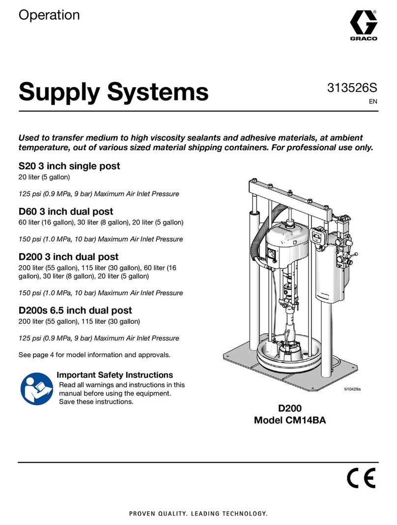
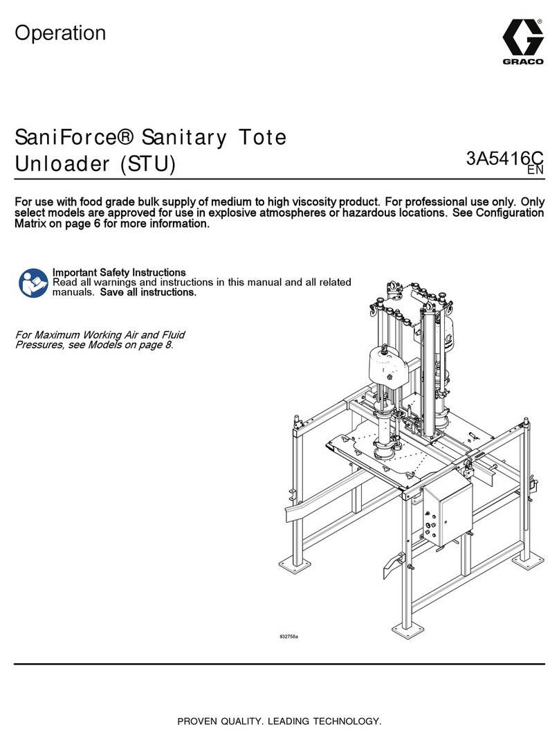
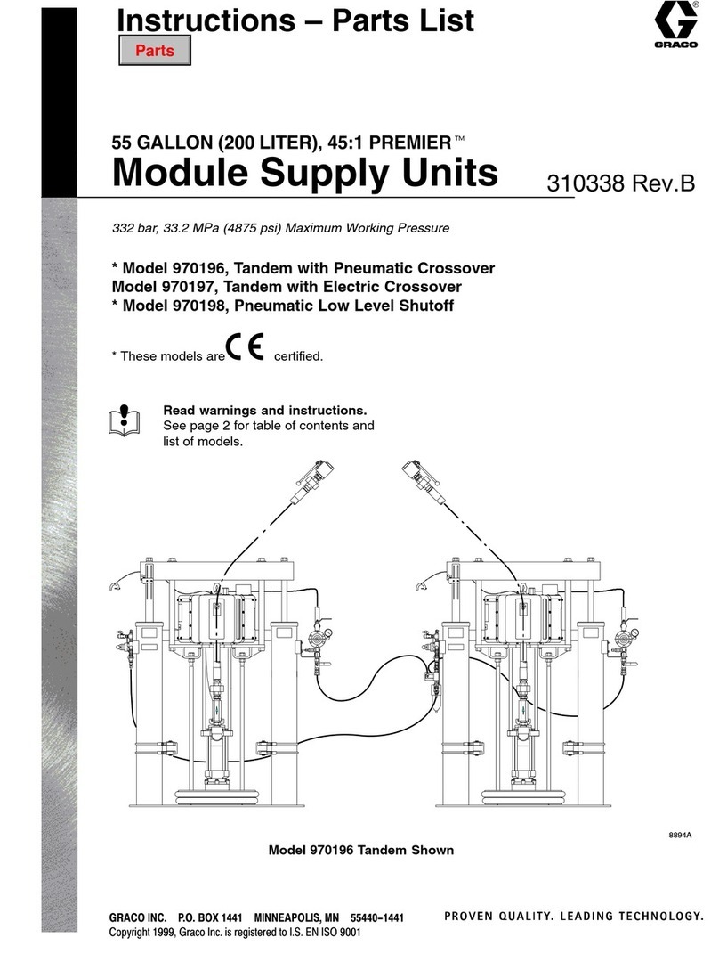
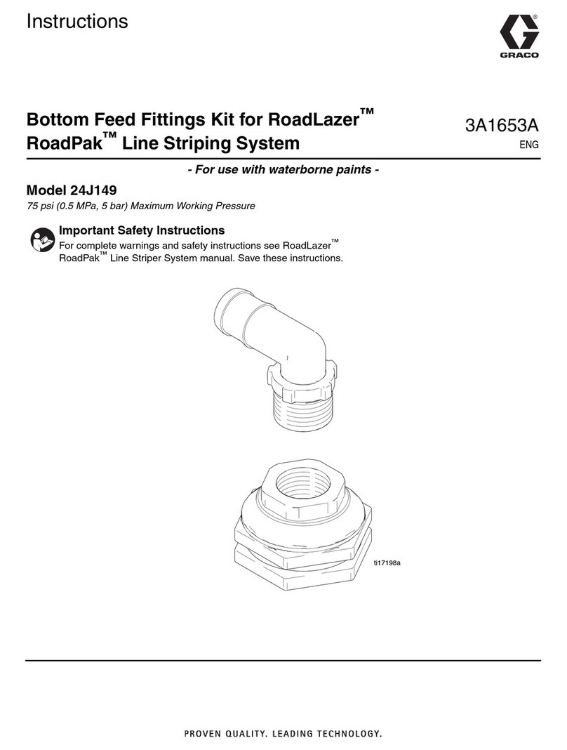
Graco 236-931 Operation manual

308–288
Rev. B
Supersedes A
INSTRUCTIONS-PARTS
LIST
INSTRUCTIONS
This
manual contains important
warnings and information.
READ AND KEEP FOR REFERENCE.
Plural
Component Mix Manifold
For Proportional Mixing of Plural Component Coatings
3000 psi (207 bar) Maximum Fluid Working Pressure
100 psi (7 bar) Maximum Air Input Pressure
Model
236–931
01909A
GRACO INC. P.O. BOX 1441 MINNEAPOLIS, MN 55440–1441

COPYRIGHT 1993, GRACO INC.

Table
of Contents
Warnings 2.
. . . . . . . . . . . . . . . . . . . . . . . . . . . . . . . . . . . . .
How
the Plural Component Mix Manifold W
orks 4.
. . .
Installation 6
. . . . . . . . . . . . . . . . . . . . . . . . . . . . . . . . . . . .
Operation 10
. . . . . . . . . . . . . . . . . . . . . . . . . . . . . . . . . . . .
Maintenance 13
. . . . . . . . . . . . . . . . . . . . . . . . . . . . . . . . . .
Troubleshooting 14
. . . . . . . . . . . . . . . . . . . . . . . . . . . . . . .
Service 16
. . . . . . . . . . . . . . . . . . . . . . . . . . . . . . . . . . . . . .
Parts
Drawings and Lists
Purge V
alves 19.
. . . . . . . . . . . . . . . . . . . . . . . . . . . . .
Dispense
V
alves 20.
. . . . . . . . . . . . . . . . . . . . . . . . . .
Manifold 22
. . . . . . . . . . . . . . . . . . . . . . . . . . . . . . . . . .
Accessories 24
. . . . . . . . . . . . . . . . . . . . . . . . . . . . . . . . . .
Technical
Data
26.
. . . . . . . . . . . . . . . . . . . . . . . . . . . . . . .
Dimensions 26
. . . . . . . . . . . . . . . . . . . . . . . . . . . . . . . . . . .
Warranty Back
Cover
.
. . . . . . . . . . . . . . . . . . . . . . . . . . . .
Graco
Phone Numbers
Back Cover
.
. . . . . . . . . . . . . . . .
Symbols
Warning Symbol
WARNING
This
symbol alerts you to the possibility of serious
injury or death if you do not follow the instructions.
Caution Symbol
CAUTION
This
symbol alerts you to the possibility of damage to
or destruction of equipment if you do not follow the
instructions.
WARNING
FIRE, EXPLOSION, AND ELECTRIC SHOCK HAZARD
Improper
grounding, poor air ventilation, open flames, or sparks can cause a hazardous condition and
result in fire or explosion and serious injury
.
D
Ground the equipment and the object being sprayed. See
Ground the System
on page 6.
D
Provide fresh air ventilation to avoid the buildup of flammable vapors from solvent or the fluid being
sprayed.
D
Extinguish all the open flames or pilot lights in the spray area.
D
Keep the spray area free of debris, including solvent, rags, and gasoline.
D
Do not turn on or of
f any light switch in the spray area while operating or if fumes are present.
D
Do not smoke in the spray area.
D
Do not operate a gasoline engine in the spray area.
D
If there is any static sparking while using the equipment,
stop spraying immediately
. Identify and
correct the problem.
D
Disconnect electrical power at the main switch before servicing the equipment.
TOXIC FLUID HAZARD
Hazardous
fluids or toxic fumes can cause serious injury or death if splashed in the eyes or on the
skin, swallowed, or inhaled.
D
Know the specific hazards of the fluid you are using. Read the fluid manufacturer
’
s warnings.
D
Store hazardous fluid in an approved container
. Dispose of hazardous fluid according to all local,
state and national guidelines.
DW
ear the appropriate protective clothing, gloves, eyewear
, and respirator
.

WARNING
INJECTION HAZARD
Spray
from the gun, hose leaks, or ruptured components can inject fluid into your body and cause
extremely serious injury
, including the need for amputation. Splashing fluid in the eyes or on the skin
can also cause serious injury
.
D
Fluid injected into the skin might look like just a cut, but
it is a serious injury
.
Get immediate medi
-
cal attention.
D
Always wear protective eyewear
.
D
Do not point the spray gun at anyone or at any part of the body
.
D
Do not put hand or fingers over the spray tip.
D
Do not stop or deflect fluid leaks with your hand, body
, glove, or rag.
D
Follow the
Pressure Relief Procedure
on page 10 whenever you: are instructed to relieve pres
-
sure; stop spraying; clean, check, or service the equipment; or install or clean the spray tip.
DT
ighten all the fluid connections before operating the equipment.
D
Check the hoses, tubes, and couplings daily
. Replace worn, damaged, or loose parts immediately
.
Permanently coupled hoses cannot be repaired; replace the entire hose.
INSTRUCTIONS
EQUIPMENT MISUSE HAZARD
Equipment
misuse can cause the equipment to rupture, malfunction, or start unexpectedly and result
in serious injury
.
D
This equipment is for professional use only
.
D
Read all instruction manuals, tags, and labels before operating the equipment.
D
Use the equipment only for its intended purpose. If you are uncertain about usage, call Graco, Chi
-
cago, T
echnical Assistance at 708–678–7200.
D
Do not alter or modify this equipment. Use only genuine Graco parts and accessories.
D
Check the equipment daily
. Repair or replace worn or damaged parts immediately
.
D
Do not exceed the maximum working pressure of the lowest rated system component. See the
instruction manuals of the individual system components for their maximum working pressures.
The manifold’s maximum fluid working pressure is 3000 psi (207 bar) and the maximum air input
pressure is 100 psi (7 bar).
D
Route the hoses away from the traffic areas, sharp edges, moving parts, and hot surfaces. Do not
expose Graco hoses to temperatures above 180
_F (82_
C) or below –40
_F (–40_C).
D
Do not use the hoses to pull the equipment.
D
Do not move pressurized equipment.
D
Use fluids or solvents that are compatible with the equipment wetted parts. See the
Technical
Data
section of all the equipment manuals. Read the fluid and solvent manufacturer
’
s warnings.
D
Comply with all applicable local, state and national fire, electrical and other safety regulations.
MOVING
P
ARTS HAZARD
Moving
parts, such as the fluid needle can pinch fingers. Keep clear of any moving parts when starting
or operating the equipment.
Some manifold parts are under compression. T
o avoid an eye injury
, wear protective eyewear when
servicing the equipment.

How the Plural Component Mix Manifold Works
Usage
The
standard Graco mix manifold can blend most two-
component epoxy or polyurethane paints. The mix
manifold is not for use with “quick-setting” paints
(those with a pot life of less than 15 minutes). For
information on handling quick-setting paints or abra
-
sive fluids, contact your Graco representative or Graco
T
echnical Assistance (see the back page).
Fluid Supply
The
system can be set up to mix components supplied
from pressure tanks or feed pumps. The materials can
be transferred from their original containers or from a
central paint recirculating line.
Operating Cycle
After
the desired ratio and other parameters are en
-
tered for the system, the operator energizes the elec
-
tronic controller
’
s MIX input. From that point on, nor
-
mal operation of the mix manifold is controlled by the
operation of the spray gun.
When the gun is triggered, the controller sends signals
to the solenoids to activate the solenoid valves. The
solenoid valves activate the manifold’s catalyst and
resin valves.
The two components (catalyst and resin) are intro
-
duced into the integrator chamber one at a time,
through separate fluid lines, check valves, and flow
meters. Their entry into the chamber is controlled by a
dispense valve for each component. The flow meters
monitor the exact fluid volumes being dispensed and
send electrical pulses to the controller
. The controller
monitors these pulses and signals the solenoids to turn
the dispense valves on or of
f accordingly (based on
the target volumes calculated by the controller).
The components are pre-mixed in the integrator
, then
given a homogeneous blending as they pass through a
static mixer tube. Output from the mixer tube to the
spray gun may be controlled by a fluid pressure regula
-
tor.
The two components continue to be alternately fed into
the mixing block as long as the gun is triggered. After
the trigger is released, if the gun is not triggered again
within four minutes, the system will go to an idle mode,
which closes of
f the mix manifold. When the gun is
triggered again, the system will continue the process
where it left of
f. Operation can be stopped at any time
by energizing the ST
ANDBY input or shutting of
f the
main power switch.
The following is a typical ratio cycle:
D
First, the Component A (resin) dispense valve
opens, and the fluid begins to flow into the integra
-
tor chamber
. When the correct quantity has been
dispensed (based on the calculated target value),
the component A dispense valve closes. See
Fig. 1.
D
Next, the Component B (catalyst) dispense valve
opens. The fluid begins to flow into the integrator
chamber and is lined up proportionately with the
previously-dispensed Component A sample. The B
dispense valve closes when the target volume for
Component B has been reached. See Fig. 2.
D
The process repeats itself as the spray gun is
triggered.

Functional Diagram – Component A (Resin) Dispense
01855B
Fig.
1
KEY
A Component
A (Resin) Supply Line
B
Fluid Filter
, 100 mesh minimum
C
Check V
alve
D
Flow Meter
E
Component A (Resin) Dispense V
alve
F
Air Purge V
alve
G
Fluid Shut-of
f V
alve
H
Ratio Check V
alve
J
Component B (Catalyst) Supply Line
K
Component B (Catalyst) Dispense V
alve
L
Solvent Purge V
alve
M Integrator
N
Static Mixer
P
Fluid Supply to Gun
ABCD E F
G
H
JKL
M
N
P
Functional Diagram – Component B (Catalyst) Dispense
01856B
Fig.
2
AEF JBCDK
L
G
H
M
N
P
KEY
A Component
A (Resin) Supply Line
B
Fluid Filter
, 100 mesh minimum
C
Check V
alve
D
Flow Meter
E
Component A (Resin) Dispense V
alve
F
Air Purge V
alve
G
Fluid Shut-of
f V
alve
H
Ratio Check V
alve
J
Component B (Catalyst) Supply Line
K
Component B (Catalyst) Dispense V
alve
L
Solvent Purge V
alve
M Integrator
N
Static Mixer
P
Fluid Supply to Gun

Installation
WARNING
FLAMMABLE
OR T
OXIC
V
APOR HAZARD
Provide fresh air ventilation to avoid the
buildup of flammable or toxic vapors. Do
not operate the spray gun unless ventila
-
tion fans are operating. Follow all nation
-
al, state, and local codes regarding air
exhaust velocity requirements.
NOTE:
D
Have the system binder (a collection of manuals
and diagrams in a three-ring binder
, supplied with
the system by Graco) available during installation.
D
Reference numbers and letters in parentheses in
this manual’
s text refer to the numbers and letters
in the illustrations.
D
Be sure all accessories are adequately sized and
pressure-rated to meet the system’s requirements.
D
Connect the fluid and air supply lines as instructed
in this manual and the system binder
.
The following instructions generally presume a stan
-
dard system using pressure tanks to supply the paint
components and solvent. See also
Optional Fluid
Supplies
, below
, for possible variations and their
ef
fect on the instructions.
Fluid Supply
The
following installation and operation instructions
generally presume a standard system, using pressure
tanks to supply the paint components and solvent.
The Optional Fluid Supplies
listed below are two
possible variations and their effect on the instructions.
Optional Fluid Supplies
NOTE:
The fluid supply must be free of pressure
spikes, which are commonly caused by a pump stroke
changeover
. If necessary
, install pressure regulators
or a surge tank on the fluid inlets to the mix manifold,
to reduce the fluid supply pressure. Contact Graco for
information on fluid pressure regulators.
Supplying Fluid Through Circulating Lines
If there is a central paint recirculating line in your shop,
the mix manifold can be connected to it instead of to
pressure tanks. Other than references to the pressure
tanks, operation is the same as described in this man
-
ual.
For maintenance and safety
, you must install a ball
valve between each supply line and the mix manifold.
Supplying Fluid Through Pail or Drum Pumps
Instead of pressure tanks, the mix manifold can be
supplied by pail or drum pumps. Operation is the
same, other than references to the pressure tanks.
Ground the System
(See Fig. 3)
WARNING
FIRE,
EXPLOSION, AND ELECTRIC
SHOCK HAZARD
T
o reduce the risk of fire, explosion, or
electric shock:
D
The mix manifold must be electrically
connected to a true earth ground; the
ground in the electrical system is not
sufficient.
D
All wires used for grounding must be
10 gauge minimum.
D
Refer to your local code for the requirements for
a “true earth ground” in your area.
D
Also read and follow the warnings on page 2.
NOTE:
A ground wire and clamp, part no 222–01
1, are
available from Graco.
Plural Component Mix Manifold
The mix manifold must be electrically connected to the
same true earth ground point as the controller enclo
-
sure. Dif
ferent ground points may cause current to flow
through the meter cables, causing incorrect signals.
The ground wire can be connected to the mix manifold
or to the mix manifold mounting surface if there is
electrical continuity between the mounting surface and
the mix manifold.
PrecisionMix System: Solenoid Enclosure
Connect a ground wire from the solenoid enclosure’
s
grounding lug to the same point as the mix manifold
mounting surface’
s ground wire.
Controller
Ground the controller as instructed in the controller
manual. The controller enclosure and the mix manifold
must be connected to the same true earth grounding
point.

Installation
Check the Resistance
WARNING
FIRE,
EXPLOSION, AND ELECTRIC
SHOCK HAZARD
T
o reduce the risk of fire, explosion, or
electric shock the resistance between
the system components and true earth
ground must be less than 25 ohms.
Have a qualified electrician check the resistance be
-
tween each system component and the true earth
ground. The resistance must be less than 25 ohms. If
the resistance is greater than 25 ohms, a dif
ferent
ground site may be required. Do not operate the sys
-
tem until the problem is corrected.
02810A














Controller
Enclosure
Solenoid Enclosure’s Grounding Lug
Solenoid Enclosure
Precision Mix:
Solenoid Enclosure
Grounding Wire; must connect to the
mix manifold mounting surface at the
same point as the mounting
surface ground wire
Flow Meter Cable
Ground Wire connection point for the
solenoid enclosure’s grounding wire
and mix manifold‘s mounting surface
grounding wire
Mix Manifold Ground Wire; must be
connected to same true earth ground
as the controller enclosure is
connected to
T
rue Earth Ground; check your local
code for requirements
Controller Enclosure Grounding Wire;
must be connected to same true earth
ground as the manifold mounting
surface is connected to
Controller Enclosure’
s Grounding Lug
Controller Grounding Wire
(green-yellow wire)
Controller
NOTE:
If mix manifold cannot be
grounded
by connecting a ground wire
to
the mounting surface ,
as shown here, connect ground wire
between
mix manifold metal fitting
and
true
earth ground









KEY


Fig.
3
Typical
PrecisionMix system shown




9
9

Installation
Fig
4
R1
R2
A1
A2
KEY
A1Air
Purge OFF Air Pilot Line
A2
Air Purge ON Air Pilot Line
A3
Air Purge Inlet
C1
Catalyst OFF Air Pilot Line
C2
Catalyst ON Air Pilot Line
D
Flow Meter
(Model PPM 3100 shown)
D1
Fluid Line from Flow Meter
H1
Ratio Check Fluid Line
J
Component B (Catalyst) Supply Line
P
Fluid Line to Spray Device
Q
Component A (Resin) Supply Line
R1Resin
OFF Air Pilot Line
R2
Resin ON Air Pilot Line
R3“W
eep Hole” or lubricator inlet
(optional)
R4
Dump V
alve Outlet
(optional)
S1
Solvent Purge OFF Air Pilot Line
S2
Solvent Purge ON Air Pilot Line
S3
Solvent Purge Inlet
Y
Grounding Clamp and Wire
C1
C2
S1
S2
J
D
D1
S3
H1
P
R4
R3
01910A
D1
A3
Q
Y
DISPENSE
V
ALVE
PURGE V
ALVE
OFF
ON
OFF
ON
R1
or C
1
R2
or C
2
D1
R3A3
or S
3
A2
or S
2
A1
or S
1
01912A 01914A
Typical
PrecisionMix
system shown

Installation
Connect the Fluid Supply Lines
NOTES:
DFilter
the paint and solvent with a 100 mesh or
better fluid filter
.
D
Be sure all fluid hoses are properly sized for your
system. Use only grounded hoses.
D
Some systems may require an optional fluid pres
-
sure regulator and gauge on the manifold static
mixer outlet to control fluid pressure to the gun.
Refer to the system binder
.
D
Refer to Fig. 4 and the system binder to connect
the fluid lines.
1.
Connect the Component A (resin) supply line (Q).
2. Connect
the Component B (catalyst) supply line (J).
3. Connect
the solvent supply line to the solvent purge
valve
inlet (S
3).
4. To
automatically lubricate the
dispense valves pack
-
ings, connect a lubricator to the top inlet (R3) of the
dispense
valves fluid housings.
Connect the Air Supply Hoses and Air
Pilot Lines
NOTES:
DThe
air supply must be filtered to 10 micron or
better or the air solenoids will clog frequently
.
DT
o avoid contaminating your paint products, be sure
the air supply is free of oil and water
.
D
The mix manifold requires a compressed air supply
pressure of 60 to 80 psi (4.2 to 6 bar), with most
applications using around 80 psi (6 bar).
D
Be sure all air supply hoses are properly sized for
your system. Use only grounded air hoses.
D
Refer to Fig. 4 and the system binder to connect
the air pilot lines.
1. Connect the air supply hoses to the air inlet of the
resin, catalyst, and solvent supply tanks if pressure
tanks are used. Include a regulator and shut-of f
valve
in each line.
2. Connect
the air pilot
lines between the air solenoids
and
the mix manifold. The air pilot lines must be less
than
6 feet (1.83 meters) long.
3. Pressurize
the system with air
, and check for leaks at
all connections. Relieve the air pressure after the
test.
Purge the Mixing System Before Using It
The
mix manifold was tested with lightweight oil at the
factory
. Before operating for the first time, thoroughly
purge the system with solvent to prevent contamina
-
tion of your fluids.
10308-288
Operation
NOTE:
The following instructions presume a standard
system; with pressure supply tanks for the paint and
solvent. Also see
Optional Fluid Supplies
on page
6 for possible variations and their ef
fect on the in
-
structions.
Pressure Relief Procedure
WARNING
INJECTION
HAZARD
The system pressure must be manually
relieved to prevent the system from
starting or spraying accidentally
. Fluid
under high pressure can be injected through the
skin and cause serious injury
. T
o reduce the risk of
an injury from injection, splashing fluid, or moving
parts, follow the
Pressure Relief Procedure
whenever you:
D
are instructed to relieve the pressure,
D
stop spraying,
D
check or service any of the system equipment,
D
install or clean the spray tip.
1.
Set the operator switch to ST
ANDBY.
2.
Relieve fluid and air pressure at the component
and solvent feed pumps or pressure pots, as
explained in their separate instruction manuals.
3.
Set the operator switch to MIX.
4.
Hold a metal part of the spray gun firmly to the
side of a grounded metal pail, and trigger the gun
to relieve fluid pressure.
5.
Set the operator switch to ST
ANDBY.
NOTE:
Always disconnect all power to the mix man
-
ifold before cleaning or servicing it.
Plural Component Mix Manifold Controls
(See Fig. 5)
CAUTION
To
avoid damaging the mix manifold valves, do not
use a wrench to tighten or loosen the adjustment
knobs.
NOTE:
D
In the following instructions, to “open” the valves,
turn their knobs
out
. T
o “close” the valves, turn their
knobs
in
. Fully close the valves (turn the knobs all
the way in) before beginning to adjust them.
DY
ou may want to put a piece of tape on the knobs
after they are properly set to discourage anyone
from changing the setting.
Dispense V
alve Knobs (A)
Use to adjust the resin and catalyst dispense valve
openings, limiting the maximum fluid flow rate into the
mixing block and minimizing valve response time.
NOTE:
This setting is of minimal importance when the
spray gun controls the process, except that the valves
must be open enough to allow adequate fluid flow
. For
most applications, set the knobs 2/3 of a turn open.
Purge V
alve Knobs (B)
Use to adjust the air and solvent purge valve openings,
limiting the flow rate into the mixing block. For most
applications, set the knobs 1 turn open.
Fluid Shut-Off Knobs (C)
Use to close the fluid ports from the volume counters
to the integrator during a ratio check or meter calibra
-
tion. The knobs should be fully open (turned all the
way out) during normal RUN/MIX mode of operation.
Ratio Check V
alve Knobs (D)
Use to measure the amount of resin and catalyst
component flowing to the mixing block (volume ratio).
These knobs should not be opened unless the fluid
shut-of
f knobs are closed.
NOTE:
The ratio check valves should be purged with
solvent immediately after being used.
308-28811
Operation
Purging the Mixing System
WARNING
INJECTION
HAZARD
T
o reduce the risk of a serious injury
from injection or splashing fluid:
D
Follow the
Pressure Relief Proce
-
dure
on page 10 whenever you are
instructed to relieve the pressure.
D
If you are using a high pressure gun*, remove
the spray tip before purging. Relieve pressure
before removing the spray tip.
DW
ear protective eyewear
.
D
Use the lowest possible fluid pressure when
purging.
WARNING
FIRE AND EXPLOSION HAZARD
T
o reduce the risk of fire, explosion and
serious injury when purging the mix
manifold, be sure the entire system and
flushing pails are properly grounded.
Follow the instructions in your gun man
-
ual to ground your gun while purging.
Follow the purging procedure in the controller manual.
Purge the system at the following times:
D
During initial startup
D
At the end of each workday
D
Before any break longer than the pot life of the fluid
D
Before servicing the system if possible or after
servicing if production will not resume right away
.
Solvent purges the right-hand (Component B/catalyst)
side of the mixing block and the inner tube of the inte
-
grator
. Air purges the left-hand (Component
A/resin)
side of the mixing block and the outer tube of the inte
-
grator.
Note for PrecisionMix System:
Solvent may be used
to purge both sides of the mixing block, but this will
result in longer purge sequences and high solvent
usage. Call Graco Chicago Customer Service at
708–678–7200 before choosing this option.
Fig. 5
A
KEY
A Dispense
V
alve Knobs
B
Purge V
alve Knobs
C
Fluid Shut-of
f Knobs
D
Ratio Check V
alve Knobs
B
D
01909A
C
*
A gun is considered
high pressure
when its maximum working pressure is 900 psi [62 bar] or greater
.
Airless
spray guns and
air-assisted airless
spray guns are high pressure guns.
Air spray
guns are low pressure guns.
12308-288
Operation
Setting the Fluid Supply Pressure
Turn
on the air supply and recharge the paint and
solvent tanks with air
. Adjust the air pressure to:
Solvent
– 70 psi (5 bar).
Resin and Catalyst
– 30 to 70 psi (2 to 5 bar).
Fluid pressures should be equal unless one compo
-
nent is more viscous, in which case the more viscous
component could require a higher pressure setting.
Adjust the pressures until the fluid flow rate at the gun
is the same for both the Component A and B dispense.
Starting Production
WARNING
INJECTION
HAZARD
T
o reduce the risk of a serious injury
from accidental spray from the gun,
splashing fluid, or moving parts, follow
the
Pressure Relief Procedure
on page 10 when
-
ever you:
D
are instructed to relieve the pressure,
D
stop spraying,
D
check or service any of the system equipment,
D
install or clean the spray tip.
NOTE:
D
The operation of the manifold is dependant on the
operation of the controller and the controller set
-
tings. See the controller manual for complete start
-
up, ratio check, purging, and production proce
-
dures.
D
When you first start up the system after it has been
shut down for a period of time, the relays, sole
-
noids, and valves for Components A and B will
cycle rapidly until system pressure is built back up.
This is normal.
1.
Check that the fluid supplies for the Component A,
Component B, and solvent are filled.
2.
Check that fluid valves are turned on and the fluid
pressure to the mix manifold is properly set.
3.
Check that the air pressure to the solenoids is
properly set. Most applications require about 80
psi (6 bar) pressure. T
o operate properly
, do not go
below 75 psi (5.2 bar) or exceed 95 psi (6.6 bar)
pressure.
4.
Check that the mix manifold fluid shut-of
f knobs,
dispense valve knobs, and purge valve knobs are
set properly
. Start with the settings recommended
in
Plural Component Mix Manifold Controls
on
page 10, then adjust the valves as needed.
5.
Follow the operating instructions for your control
-
ler.
During Production:
D
Make sure that all air is removed from the fluid lines
of the system.
D
If the fluid output is too low or too high, adjust the
fluid pressure with the fluid supply pressure regula
-
tors.
CAUTION
Do not use the first 4 to 5 oz. (120 to 150 ml) of
material from the system, as it may not be thor
-
oughly mixed due to alarms while loading material
into the system.
D
Check the fluid supply pressure regulators. The
fluid flow rate at the spray gun should be the same
regardless of whether the Component A or B
dispense valves are open. The pressure adjust
-
ments of each component will vary with each
components viscosity
. In general, start with the
same feed pressures for Component A and B.
D
Check or reset the air regulator in the atomizing air
line.
308-28813
Maintenance
Daily Maintenance
DPurge
the mixing system at the end of production.
D
Check the fluid supplies for the Component A,
Component B, and solvent and refill them as nec
-
essary.
D
Inspect the manifold and other fluid line compo
-
nents for fluid leaks.
D
Make sure the meter cables and air pilot lines are
securely connected.
Weekly Maintenance
DDisconnect
the integrator assembly
. Clean and
inspect it, and ensure that the small distributor
holes in the integrator tube (6) are all open. See
Fig. 6. The integrator may need cleaning more or
less frequently
, depending on the fluid being mixed.
D
Clean and inspect the fluid and air filters.
D
Adjust packing nuts on the dispense valves and
purge valves.
Preventive Maintenance
At
least once a year
, take apart the mix manifold,
which includes the mixing block, dispense valves,
purge valves, and ratio check valves. Clean and in
-
spect them, and replace all o-rings and v-packings.
Repair kits are available from Graco. See the
Service
section.
Fig. 6
KEY
6 Integrator
T
ube
7
Integrator Housing
6
7
01911B
14308-288
Troubleshooting
WARNING
INJECTION
HAZARD
T
o reduce the risk of a serious injury
from accidental spray from the gun,
splashing fluid, or moving parts, follow
the
Pressure Relief Procedure
on page 10 before
checking or servicing the system and whenever
you are instructed to relieve the pressure.
WARNING
EQUIPMENT MISUSE HAZARD
T
o reduce the risk of serious injury
, including elec
-
tric shock, the equipment must only be serviced by
trained, qualified personnel.
CAUTION
T
o avoid damaging the mix manifold valves, do not
use a wrench to tighten or loosen the adjustment
knobs.
NOTE:
Have the system binder (collection of manuals
and diagrams in a three-ring binder
, supplied with the
system by Graco) available before you begin trouble
-
shooting.
An operational problem can be caused by a problem
with the meters, controller
, solenoid valves, as well as
the manifold.
1.
Check the system for any visible faults or errors to
help isolate the problem:
a.
Check that all of the air and fluid tubes, hoses,
and electrical cables are properly connected.
b.
Check that the system valves and controls are
properly set for operation.
c.
Check that the fluid supply
, solenoids, and
spray gun have suf
ficient air pressure.
d.
Check the fluid supplies for the Component A,
Component B, and solvent and refill them as
necessary.
2.
If there is a fluid flow problem, refer to the
Func-
tional Diagrams on page 5 to see how the fluid
should flow through the manifold.
3.
If there is a process control problem, refer to the
controller manual.
Common Causes for Mixing Problems
DThe
flow rate is too high
D
Highly unbalanced pressures from the fluid supply
system
D
Slow actuation of the resin or catalyst valves
D
System Leaks
Checking for Unbalanced Pressures
1.
Check the catalyst and resin pressures.
2.
If the pressures are not about equal,
adjust both
fluid supply pressures with the fluid regulators, un
-
til the pressures are about the same.
3.
If the pressures are already about equal,
verify
that the resin and catalyst valves are operating
properly.
Checking the Actuation of the Valves
Manually operate the valves by actuating the sole
-
noids. The valves should snap open and shut quickly
.
If the valves move slowly
, it could be caused by:
D
air pressure to the valve actuators is too low
,
D
an interruption in the valve actuating air caused by
dirt or water in the air
,
D
something restricting the solenoid or tubing,
D
the packings on the dispense valves are too tight or
they need lubrication (see
Service
section),
D
air piston o-rings and packings are not lubricated
(see
Service
section),
D
a dispense valve knob is turned out too far
. See
Plural Component Mix Manifold Controls
on
page 10, for recommended settings.
308-28815
Notes
16308-288
Service
CAUTION
Purge
the mix manifold with solvent after servicing to
remove any excess grease that is used for lubricat
-
ing parts.
Tools Needed
DSet
of metric open-end wrenches
D
Set of metric hex key wrenches
DV
arious retaining ring pliers
D
Flat-blade screwdrivers.
D
Dielectric grease (Graco part no. 217–1
15)
Disassembling the Dispense Valves
WARNING
INJECTION
HAZARD
T
o reduce the risk of a serious injury
from accidental spray from the gun,
splashing fluid, or moving parts, follow
the
Pressure Relief Procedure
on page 10 before
checking or servicing the system and whenever
you are instructed to relieve the pressure.
To remove the complete dispense valve from the
mixing block:
(See Fig. 7)
1.
Disconnect the fluid line (B) from the fluid housing
(128).
2.
Disconnect the two air lines (A).
3.
Loosen the two cap screws (127) until the dis
-
pense valve is free from the mix manifold.
4.
Carefully remove the dispense valve. The valve
seat (132) and bottom o-ring (131) may fall away
.
See Fig. 8.
T
o remove just the air cylinders (1
1
1, 1
14):
(See Fig. 7 and
Fig. 8)
1.
Disconnect the two air lines (A).
2.
Unscrew the dispense valve knob (103) far enough
for the screws (101, 102) to clear it.
3.
Remove the two screws (101) that go into the
connecting rods (126). Do not remove the two
screws (102) that are secured by cap nuts (1
15).
4.
With a hex wrench or similar tool, unscrew the
packing nut (120).
5.
Pull of
f the air cylinders (1
1
1, 1
14); this is a snug
fit.
T
o disassemble the top air cylinder (1
11):
WARNING
MOVING P
ARTS HAZARD
The air cylinders (1
1
1, 1
14) of the valve
are spring-loaded, and parts may fly out
or spring apart when the valve is disas
-
sembled. T
o reduce the risk of an eye injury
, wear
protective eyewear and follow the procedure below
.
(See Fig. 7 and Fig. 8
)
NOTE:
Repair Kit 948–591 is available to repair the
dispense valves. Order one kit for each valve. The
repair parts in the kit are marked with an asterisk (*) in
Fig. 8.
1.
Remove the top air cylinder (1
1
1); see previous
procedure.
2.
Unscrew the dispense valve knob (103).
Fig. 7
103
A
B
126
128
120
115
127
101
111
114
01912A
102
308-28817
Service
3. Slowly
remove the two screws (102) secured by
cap nuts (1
15), while holding the cylinder cap (104)
down.
Be careful, the air cylinders (1
1
1, 1
14) are under
compression and will spring apart and the detent
pin (105) will spring out from the cylinder cap
(104). Slowly let up on the cap to release the
spring compression.
4.
Remove the top retaining ring (108) from the
piston rod (1
18).
5.
Pull the piston rod (1
18) down and hook it under
the top piston (109) with a hex wrench or similar
tool.
6.
Remove the remaining retaining rings (108) to
complete the disassembly of the air cylinders.
7.
Clean and inspect all parts. Inspect the o-rings
(1
10, 112, 113, 1
16) on the pistons (109) and
piston rod (1
18). Replace parts as necessary
.
Lightly lubricate the o-rings with dielectric grease.
Assemble parts in reverse order of disassembly
.
When
reassembling,
be sure the two air connection
ports will be facing the outside of the machine. Set the
knob (103) 2/3 of a turn open from fully closed.
To disassemble the fluid housing (128):
(See Fig. 7 and Fig. 8
)
1.
Remove the top air cylinder (1
1
1); see previous
page.
2.
Remove the glands (122, 123, 124) and v-pack
-
ings (121) from the fluid housing (128).
3.
Clean and inspect all parts. Inspect the fluid
needle (125), seat (132), and o-rings (131) for
wear
. If only one side of the seat is worn, the seat
can be reversed and reused.
4.
Replace parts as necessary
. Lightly lubricate the
packings with dielectric grease. Assemble parts in
reverse order of disassembly
.
5.
Adjust the packing nut (120).
101
103
102
104
105
106
107
108
109
*110
108
111
*112
*113
108
109
*110
108
114
*112
115
132 131*
128
126
125*
127
124*
121*
123*
121*
120
119
118
116*
122*
Fig. 8
Lips
face down
Lightly lubricate with
dielectric grease
Seat is reversible
SER
VICE NOTES:
01913A
133














130
18308-288
Service
Disassembling the Purge Valves
WARNING
INJECTION
HAZARD
T
o reduce the risk of a serious injury
from accidental spray from the gun,
splashing fluid, or moving parts, follow
the
Pressure Relief Procedure
on page 10 before
checking or servicing the system and whenever
you are instructed to relieve the pressure.
To
remove the complete purge valve from the
mixing
block and mounting plate:
(See Fig. 9)
1.
Disconnect the air line connections (A).
2.
Remove the two screws (52).
T
o disassemble the purge valve:
(See Fig. 9 and the
Parts Drawing
on page 19)
WARNING
MOVING P
ARTS HAZARD
The air cylinders (63, 70) of the valve
are spring-loaded, and parts may fly out
or spring apart when the valve is disas
-
sembled. T
o reduce the risk of an eye injury
, wear
protective eyewear and follow the procedure below
.
NOTE:
Repair Kit 237–948 is available to repair the
purge valves. Order one kit for each valve. See the
parts list on page 19.
1.
Hold the piston rod (64) with a hex wrench or
similar tool, and unscrew the coupling (58).
2.
Slowly remove the four screws (72), while holding
the top air cylinder (70) down.
Be careful, the air cylinders (63, 70) are under
compression and will spring apart.
Slowly let up on the top air cylinder (70) to release
the spring compression.
3.
Inspect the o-rings (62, 66, 69, 71) on the piston
(65) and piston rod (64). See the
Parts Drawing
,
page 19.
4.
Remove the packing (56) from the fluid housing
(54).
5.
Clean and inspect all parts. Inspect the fluid
needle (59) and seat (79) for wear
. If only one side
of the seat is worn, the seat can be reversed and
reused.
6.
Replace parts as necessary
. Lightly lubricate the
packings with dielectric grease. Assemble parts in
reverse order of disassembly
.
7.
Adjust the packing nut (57).
When
reassembling,
be sure the two air connection
openings are on the side of the valve, facing the
outside
of the machine. When connecting the purge
valve to the mix block, it may be helpful to open the
valve pneumatically
.
58
Fig. 9
52
64
A
70
63
01914A
57
72
308-28819
Purge
V
alve Parts
Part No. 236–929, Purge Valve
Ref.
No. Part
No.
Description Qty.
51 111–119 SCREW
, socket head;
M4 x 0.7 x 25 mm
2
52 111–120 SCREW
, socket head;
M5 x 0.8 x 35 mm
2
53*{111–457
O-RING,
r1
54{190–442
HOUSING, fluid
(see NOTE, below)
1
55 111–123
GLAND, female
1
56*{111–124 P
ACKING, fluid
1
57 189–904 NUT
, packing
1
58 190–054
COUPLING, valve
1
59*{190–441
NEEDLE, fluid (see NOTE, below)
1
60 190–037
HOUSING, valve
1
62*{156–454
O-RING, Buna–N
1
63 190–036 VAL
VE CYLINDER
1
64 111–132
ROD, piston
1
65 111–133 PIST
ON, valve
1
66*{104–093
O-RING, Buna–N
1
67 111–135 SPRING 1
68 112–850 SCREW
; M5 x .8 x 8.0 mm
1
69*{111–137
O-RING, Buna–N
1
Ref.
No.
Part No.
Description Qty.
70 190–038
AIR CYLINDER
1
71*{111–139
O-RING, Buna–N
1
72 111–140 SCREW
, socket head;
M4 x 0.7 x 70 mm
4
73 111–141
KNOB, adjustment
1
75 112–676
SPRING, compression
1
76 190–046
BUSHING, detent pin
1
77 112–658
PIN, detent
1
78*{111–516
O-RING, CV75
1
79*{190–609 SEAT
, needle
1
* These
parts are included in Repair Kit 237–948, which
may be purchased separately
.
{
These parts are included in Conversion Kit 238–242,
which may be purchased separately
.
NOTE:
Conversion Kit 238–242 is needed when converting
the purge valve to the replaceable seating configuration. The
needle (item 59) and housing (item 54) from the previous
purge valve assembly
, part no. 224–064, are not compatible
with the new configuration.
51
53*{
54{
52
5556*{
57 58
59*{
60
62*{63
64
65
66*{
67
68
69*{
70
71*{
72 73
01915A
78*{
79*{
75
77
76
Lightly
lubricate with
dielectric grease
Seat is reversible
SER
VICE NOTES:







PTFE

Dispense
V
alve Parts
101
103
102
104
105
106
107
108
109
*110
108
111
*112
*113
108
109
*110
108
114
*112
115
132 131*
128
126
125*
127
124*
121*
123*
121*
120
119
118
118a
116*
122*
01913A
133
130

Other Graco Industrial Equipment manuals

Graco C27130 Operation manual

Graco

Graco C27130 Operation manual

Graco D60 Instruction Manual

Graco

Graco D60 Instruction Manual

Graco Ex35 User manual

Graco

Graco Ex35 User manual

Graco 918478 Operation manual

Graco

Graco 918478 Operation manual

Graco 918468 Datasheet

Graco

Graco 918468 Datasheet

Graco 25M777 User manual

Graco

Graco 25M777 User manual

Graco 224667 Operation manual

Graco

Graco 224667 Operation manual

Graco InvisiPac GS35 Plug-Free Operation manual

Graco

Graco InvisiPac GS35 Plug-Free Operation manual

Graco G-Flex 1500 Use and care manual

Graco

Graco G-Flex 1500 Use and care manual

Graco InvisiPac GS35 Plug-Free Operation manual

Graco

Graco InvisiPac GS35 Plug-Free Operation manual

Graco 25C528 Parts list manual

Graco

Graco 25C528 Parts list manual

Graco G3 Series User manual

Graco

Graco G3 Series User manual

Graco ThermoLazer 200TC Operating instructions

Graco

Graco ThermoLazer 200TC Operating instructions

Graco 239802 Operation manual

Graco

Graco 239802 Operation manual

Graco Therm-O-Flow 200 Operation manual

Graco

Graco Therm-O-Flow 200 Operation manual

Graco SERIES F User manual

Graco

Graco SERIES F User manual

Graco 15H877 User manual

Graco

Graco 15H877 User manual

Graco Reactor 2 E-30 Instruction Manual

Graco

Graco Reactor 2 E-30 Instruction Manual

Graco 24A431 User manual

Graco

Graco 24A431 User manual

Graco 25C453 Parts list manual

Graco

Graco 25C453 Parts list manual

Graco Pulse 25T462 User manual

Graco

Graco Pulse 25T462 User manual

Graco XM 255684 User manual

Graco

Graco XM 255684 User manual

Graco TI12552a User manual

Graco

Graco TI12552a User manual

Graco 260405 User manual

Graco

Graco 260405 User manual

Popular Industrial Equipment manuals by other brands

ABB BEF 185H/OE S A250 operating instructions

ABB

ABB BEF 185H/OE S A250 operating instructions

Nord Drivesystems SK 510P manual

Nord Drivesystems

Nord Drivesystems SK 510P manual

Fein RSG Ex 1500 A Series manual

Fein

Fein RSG Ex 1500 A Series manual

ABB XAC25200 Operation manual

ABB

ABB XAC25200 Operation manual

Yost Vises 10904 manual

Yost Vises

Yost Vises 10904 manual

Sagola 6110 Inox instruction manual

Sagola

Sagola 6110 Inox instruction manual

Bender MRCDB300 Series quick start guide

Bender

Bender MRCDB300 Series quick start guide

Greenbroz 215 CannaGin user manual

Greenbroz

Greenbroz 215 CannaGin user manual

Dell PowerVault 124T LTO-3 user guide

Dell

Dell PowerVault 124T LTO-3 user guide

Simplex 4604-9201 Installation and configuration instructions

Simplex

Simplex 4604-9201 Installation and configuration instructions

DEPURECO miniAIR Series Use and maintenance manual

DEPURECO

DEPURECO miniAIR Series Use and maintenance manual

Schmalz SNG-Y Series Service instructions

Schmalz

Schmalz SNG-Y Series Service instructions

Bentone BFG 1-2 H3 Installation and maintenance  instruction

Bentone

Bentone BFG 1-2 H3 Installation and maintenance instruction

Mayr EAS-dutytorque 404 400 Series Installation and operational instructions

Mayr

Mayr EAS-dutytorque 404 400 Series Installation and operational instructions

Eaton NZM1-XBR Instruction leaflet

Eaton

Eaton NZM1-XBR Instruction leaflet

Rockwell Automation Allen-Bradley 1606-XLSREDS40HE Reference manual

Rockwell Automation

Rockwell Automation Allen-Bradley 1606-XLSREDS40HE Reference manual

GHIELMETTI GKV 10x40 621 SK R K Operation manual

GHIELMETTI

GHIELMETTI GKV 10x40 621 SK R K Operation manual

Spartan Equipment Mini Pick-Up Broom Operator's manual

Spartan Equipment

Spartan Equipment Mini Pick-Up Broom Operator's manual

manuals.online logo
manuals.online logoBrands
  • About & Mission
  • Contact us
  • Privacy Policy
  • Terms and Conditions

Copyright 2025 Manuals.Online. All Rights Reserved.