manuals.online logo
Brands
  1. Home
  2. •
  3. Brands
  4. •
  5. Allegion
  6. •
  7. Door Lock
  8. •
  9. Allegion FALCON 25-V User manual

Allegion FALCON 25-V User manual

*640008-00*
640008-00
2
1
40 ¹⁄₄" (102 cm) from finished floor
102 cm desde el piso terminado
102 cm à partir du plancher fini
RHR
RHR LHR
If sexbolts are in box, see Sexbolt Preparation on back page
Si los pernos macho-hembra se encuentran en la caja,
consulte preparación de pernos macho-hembra en la página posterior
Si les colonnettes sont dans la boîte, voir la préparation
de colonnettes au verso de la page
!
Draw Exit Device Centerline ( )
Sacar línea central del dispositivo
de salida de misión ( )
Tracer l'axe du dispositif ( )
#10-24
Use to lock down pushbar
Utilícela para asegurar hacia abajo
la barra de empuje
Utilisé pour verrouiller la barre antipanique
Dogging Key Llave del trinquete Œillet vissé
2"
(51 mm)
*Double door 25-V & 25-V only
*Puerta doble solamente 25-V y 25-V
*Porte double 25-V et 25-V seulement
*3¹⁄₂"
*1³⁄₄"
4" +
2³⁄₄"
Surface Vertical Rod Exit Device
Dispositivo de salida con varilla vertical en la supercie
Appareil de sortie de la tige verticale de surface
25-V & F-25-V
Installation Instructions
Instrucciones de Instalacion
Notice d’Installation
Servicio al cliente
1-877-671-7011 www.allegion.com
Customer Service
Service à la clientèle
© Allegion 2014
Printed in U.S.A.
640008-00 Rev. 01/14-a
7
Mark Door Using Paper Templates On Back Cover
Marque la puerta utilizando las plantillas de papel
en la cubierta posterior
Marquer la porte en utilisant les gabarits de papier
au verso du couvercle
8
Flush With Jamb
Alinee con la Jamba
À niveau avec le montant
Flush With Floor
Alinee con el piso
À niveau avec le plancher
B
A
F-25-V
#25
#10-24
₈⁄¹ )mm52(”1X)mm3("
UOORO
25-V
3
Plastic
Template
La Plantilla
Plástica
Le Gabarit
en Plastique
Mark 5 Holes
Marque 5 Agujeros
Marquer 5 Trous
RHR
LHR
4
RHR
LHR
Cut 2" Hole
Corte un orificio de 51 mm
Couper un orifice de 51 mm
If Installing Trim,
Go To Trim Instructions
Si instala una moldura vaya
a las instrucciones de moldura
Pour l'installation d'une
garniture, Voir les
« Instructions de garniture »
5
Trim
Moldura
Garniture
6
F-25-V
#25
#10-24
25-V
¹⁄₈" (3 mm) X 1" (25 mm)
OR O OU
Prepare 4 Holes
Prepare 4 orificios
Préparer 4 orifices
Device side only
Solamente de lado dispositivo
Seulement de côté de appareil
11
10
9
If Necessary, Cut Device
Si es necesario, corte el dispositivo
Couper le dispositif si nécessaire
12
Thru-bolting Trim
Moldura apernada
Vissage transversal
de garniture
Surface Mount
Montaje en la superficie
Montage en surface
25-V
F-25-V
If Necessary, Reverse Handing
Si es necesario, invierta la operación
Inverser l'assemblage si nécessaire
LHR
RHR
Always toward bottom
Siempre hacia la parte inferior
Toujours vers le bas
#25
#10-24
₈⁄¹ )mm52(”1X)mm3("
UOORO
Cover Plate Flush
Alinee la placa de la cubierta
Plaque-couvercle encastrée
EL/EA
Minimum / Minimo
5¹⁄₄"
(133 mm) 7¹⁄₂"
(191 mm)
Door Puerta Porte
1¹⁄₂" (38 mm)
Recommended
Recomendado
Recommandé
Jamb Jamba Montant
Jamb Jamba Montant
Wood/Madera/Bois
Metal/Metal/Métal
15
16
18
OR O OU
OR O OU
17
13
14
ab
c
#25
#10-24
¹⁄₈" (3 mm) x 1" (25 mm)
#25 #10-24
¹⁄₈" (3 mm)
25-V
OR O OU
F-25-V
1" (25 mm) deep/
produndidad/profundeur
OR O OU
25-V
F-25-V
25-V
F-25-V
25-V
F-25-V
Wood/Madera/Bois
Metal/Metal/Métal
25-V
F-25-V
Centered
Centré
Centrada
20
22
19
23
21
LBR 30
Bend
Flexionar
Plier
a
b
c
6' 8"
7' 0"
7' 2"
7' 6"
7' 10"
8' 0"
8' 6"
8' 10"
9' 0"
9' 6"
9' 10"
10' 0"
–
1'
1'
1'
1'
2'
2'
2'
3'
3'
3'
–
4"
10"
6"
2"
6"
2"
–
6"
2"
–
–
–
¹⁄₈"
3mm
⁷⁄₁₆”
Test Top Latch Function
Prueba de la función del seguro en la parte superior
Vérifier le fonctionnement du verrou supérieur
Latchbolt should remain retracted when
pushbar is released
El perno del seguro debe permanecer
retraído cuando
Le pêne demi-tour doit demeurer
rétracté lorsque
aUntil latch is fully extended
Extender completamente
Plein déploiement
bUntil adjustment screw
fits into slot
Hasta que el tornillo
gire en la ranura
Jusqu'à ce que la vis
pénètre dans la fente
a
b
Drill New Hole, if Necessary
Perforar un Orificio Nuevo, si es Necesario
Percer un Nouvel Orifice si Nécessaire
Prepare Top Rod Length
Preparar la Longitud de la Barra en la Parte Superior
Préparer la Longueur de la Tige Supérieure
Height
Altura
Hauteur
Extension Required
Extensión que se Requiere
Longueur Nécessaire
*Rod Cut Required
*La barra Requiere Corte
*Coupe de Tige Nécessaire
*Do not cut threaded end of top rod
*No Cortar el Etremo Roscado de la Barra Superior
*Ne pas Couper L'embout Fileté de la Tige Supérieure
With Door Closed
Con la puerta cerrada
Porte fermée
With Door Open
Con la puerta abierta
Porte ouverte
Clears Floor
& Strike
Despeje el piso
y cerrojo
Dégagé du
plancher
et du
montant
29
25
27
28
OR O OU
26
24
#25 #10-24
¹⁄₈" (3 mm) 1" (25 mm) deep/
produndidad/profundeur
OR O OU
25-V
F-25-V
25-V
F-25-V
Centered
Centré
Centrada
30
b
aPosition pushbar guide
Posicione la guía de
la barra de empuje
Guide de positionnement
de la barre antipanique
Install cover
Instale la cubierta
Installer le couvercle
Device
dispositivo
dispositif
Top Latch
Seguro superior
Haut de verrouillage
Bottom Bracket
Eje de pedalier
Bas verrou
A
⁵⁄₁₆"
(8 mm)
1¹⁄₂
"
(38 mm)
1³⁄₄"
(44 mm)
2¹⁄₂"
(64 mm)
⁹⁄₁₆"
(14 mm)
Top Strike
Cerrojo en
la parte superior
Gâche supérieure
Top Latch
Seguro en la parte superior
Verrou supérieur
FOLD PLEGAR PLIER
1¹⁄₁₆"
(27 mm)
1¹⁄₄"
(32 mm)
¹⁄₂"
(13 mm)
Bottom Bracket
Ménsula en la parte inferior
Support inférieur
FOLD PLEGAR PLIER
B
¹⁄₄"
(6 mm)
hole
orificio
orifice
through
completo
par
Sexbolt
Preparation
Perno macho-hembra
Preparación
Colonnette
Préparation
!
If sexbolts are in box, install them at steps 6, 8, & 13 per
preparation shown below
Si los pernos macho-hembra se encuentran en la caja,
instálelos en los pasos 6, 8 y 13 conforme a la preparación
como se muestra a continuación
Si les colonnettes sont dans la boîte, installez-les aux étapes
6, 8 et 13 selon la préparation illustrée ci-dessous
Wood/Madera/Bois
Metal/Metal/Métal OR
O
OU
¹³⁄₃₂"
(10 mm)
hole
orificio
orifice
¹³⁄₃₂"
(10 mm)
⁵⁄₈"
(16 mm)
⁵⁄₈"
(16 mm)
¹⁄₄"
(6 mm)
hole
orificio
orifice
through
completo
par
Wood/Madera/Bois
Metal/Metal/Métal OR
O
OU
³⁄₈"
(10 mm)
hole
orificio
orifice
³⁄₈"
(10 mm)
¹⁄₂"
(13 mm)
¹⁄₂"
(13 mm)
If installing LBR device,
do not use template “B”
Si instala el
dispositivo LBR,
No utilice la plantilla "B"
Pour l'installation d'un
dispositif LBR, ne pas utiliser
le gabarit « B »
!
Floor Cavity
Cavidad en el piso
Encoche de plancher
⁹⁄₃₂"
(7 mm)
¹⁄₄" (6 mm)
X 4
1³⁄₈"
(35 mm)
¹⁵⁄₁₆"
(24 mm)
1¹⁄₈"
(29 mm)
1³⁄₁₆"
(30 mm)
¹⁵⁄₁₆"
(24 mm)
Deep
Profundidad
Profondeur

This manual suits for next models

1

Other Allegion Door Lock manuals

Allegion NORMBAU Manual

Allegion

Allegion NORMBAU Manual

Allegion Falcon K12 User manual

Allegion

Allegion Falcon K12 User manual

Allegion MA12 User manual

Allegion

Allegion MA12 User manual

Allegion Milre MI-260S User manual

Allegion

Allegion Milre MI-260S User manual
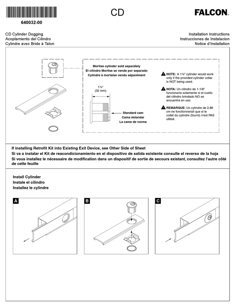
Allegion Falcon CD User manual

Allegion

Allegion Falcon CD User manual

Allegion SD9 User manual

Allegion

Allegion SD9 User manual

Allegion Schlage Control User manual

Allegion

Allegion Schlage Control User manual
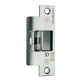
Allegion LOCKNETICS NC450 Series User manual
Allegion

Allegion LOCKNETICS NC450 Series User manual

Allegion Schlage B-Series User manual

Allegion

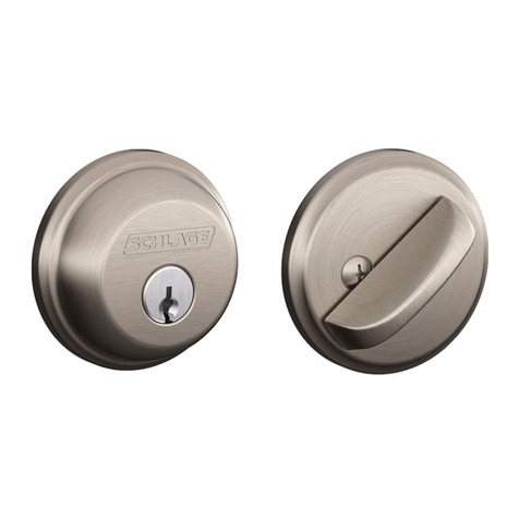
Allegion Schlage B-Series User manual
Allegion SCHLAGE 7000 SERIES User manual
Allegion

Allegion SCHLAGE 7000 SERIES User manual

Allegion SIMONS VOSS SmartHandle AX User manual
Allegion

Allegion SIMONS VOSS SmartHandle AX User manual

Allegion Schlage Custom FCT93 User manual
Allegion

Allegion Schlage Custom FCT93 User manual

Allegion Falcon MA Series User manual

Allegion

Allegion Falcon MA Series User manual
Allegion Falcon D261F User manual

Allegion

Allegion Falcon D261F User manual

Allegion Simons Voss Scandinavian Oval User manual

Allegion

Allegion Simons Voss Scandinavian Oval User manual

Allegion Milre MI-5650 User manual

Allegion

Allegion Milre MI-5650 User manual

Allegion Schlage F Series User manual

Allegion

Allegion Schlage F Series User manual

Allegion 880DT User manual

Allegion

Allegion 880DT User manual
Allegion Schlage L-Series User manual

Allegion

Allegion Schlage L-Series User manual
Allegion SimonsVoss PegaSys 2.1 User manual

Allegion

Allegion SimonsVoss PegaSys 2.1 User manual

Allegion Milre MI-5600 User manual

Allegion

Allegion Milre MI-5600 User manual

Allegion GAINSBOROUGH Austral Lock SD7 User manual

Allegion

Allegion GAINSBOROUGH Austral Lock SD7 User manual

Allegion Milre MI-480S User manual

Allegion

Allegion Milre MI-480S User manual

Allegion Falcon 25-C User manual

Allegion

Allegion Falcon 25-C User manual

Popular Door Lock manuals by other brands

danalock V3 BT HK SCANDI manual

danalock

danalock V3 BT HK SCANDI manual

CEStronics Omega Flex quick guide

CEStronics

CEStronics Omega Flex quick guide

Von Duprin 33 installation instructions

Von Duprin

Von Duprin 33 installation instructions

Philips EasyKey Alpha Series user manual

Philips

Philips EasyKey Alpha Series user manual

ZKTeco ML200 Series installation guide

ZKTeco

ZKTeco ML200 Series installation guide

Häfele PP8100 installation guide

Häfele

Häfele PP8100 installation guide

SECO-LARM SD-995C-LE25 manual

SECO-LARM

SECO-LARM SD-995C-LE25 manual

Häfele EFL 30 operating instructions

Häfele

Häfele EFL 30 operating instructions

Assa Abloy Connect 310 installation instructions

Assa Abloy

Assa Abloy Connect 310 installation instructions

Philips DDL193LAFCG/97 user manual

Philips

Philips DDL193LAFCG/97 user manual

Dormakaba Confidant RFID installation instructions

Dormakaba

Dormakaba Confidant RFID installation instructions

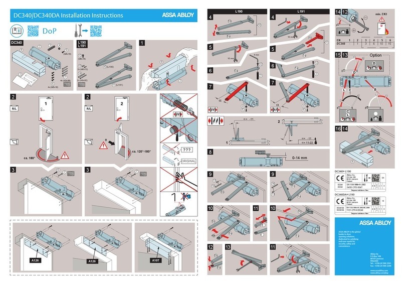
Assa Abloy DC340 installation instructions

Assa Abloy

Assa Abloy DC340 installation instructions

Samsung SHP-R80 user manual

Samsung

Samsung SHP-R80 user manual

Assa Abloy Corbin Russwin ED3400 Series installation instructions
Assa Abloy

Assa Abloy Corbin Russwin ED3400 Series installation instructions

Amplicom RingFlash 250 operating instructions
Amplicom

Amplicom RingFlash 250 operating instructions

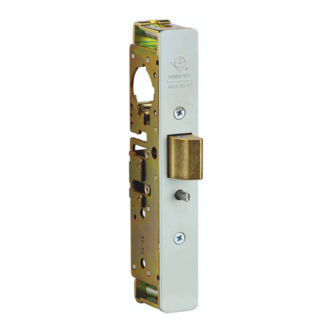
Assa Abloy ADAMS RITE 4300 Series installation instructions

Assa Abloy

Assa Abloy ADAMS RITE 4300 Series installation instructions

BANKSTON Escutcheon installation instructions

BANKSTON

BANKSTON Escutcheon installation instructions

Schlage CO-Series Service manual

Schlage

Schlage CO-Series Service manual

manuals.online logo
manuals.online logoBrands
  • About & Mission
  • Contact us
  • Privacy Policy
  • Terms and Conditions

Copyright 2025 Manuals.Online. All Rights Reserved.