Allegro ASEK-1363-40-41-T-KIT User manual

8 March, 2016
ASEK-20KT-T-KIT Page 1of 2
ASEK-1363-40-41-T-KIT Quick Guide
The ASEK-1363-40-41-T-KIT as described below is for the purpose of evaluating
certain Allegro devices in the KT package with an ASEK20.
At the time of release, this board supports A1340, A1341 and A1363 KT devices.
Note: This board does not support A1367.
ASEK-1363-40-41-T-KIT Bill of Materials
ASEK-20 Kit (Part # 85-0540-600)
oASEK-20 Chassis with main Motherboard inside (85-0540-004)
oUSB Communications Cable
oDC Power Supply/Cable with AC Outlet Adapters
oProto Board ( Part # 85-0540-103)
oRibbon Cable (Part # 85-0540-300)
ASEK-1363-40-41-T:
oASEK-20 4 Lead KT Daughterboard(Part #: 85-0614-003 Rev2)
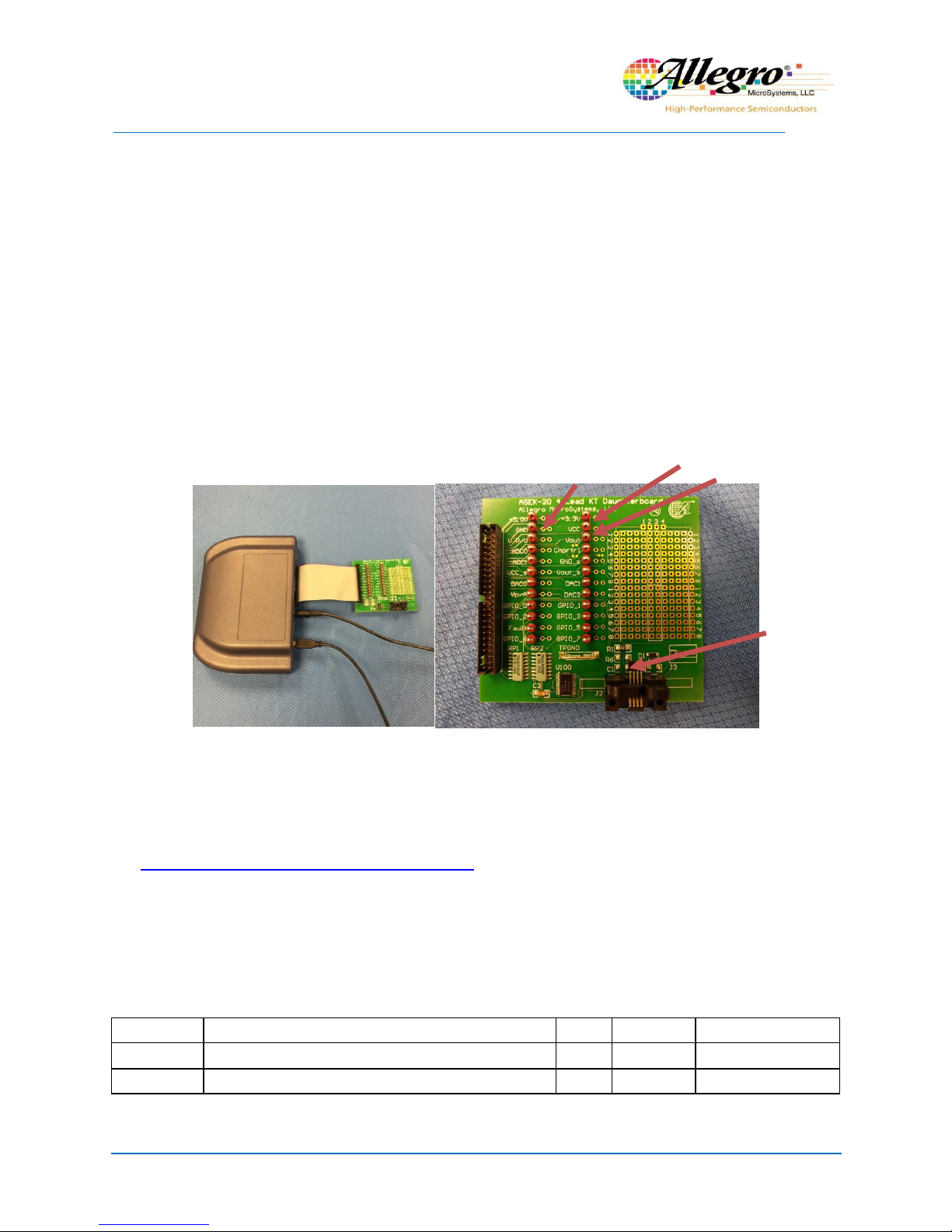
Figure 1. ASEK-20-T-KIT
Figure 2. ASEK-20 4 Lead KT Daughterboard
8 March, 2016
ASEK-20KT-T-KIT Page 2of 2
Instructions for Configuring ASEK-1363-40-41-T-KIT
1. Connect one end of the USB communications cable to a personalcomputer
2. Connect the other end of the USB communications cable to the “USB” port on the ASEK-20
chassis.
3. Connect the ribbon cable to the J2 connector on the daughterboard (85-0614-003)
4. Connect the other end of the ribboncable to the “Device Connection” port on the ASEK-20
chassis
5. Connect the DC Power Supply/Cable to the 5Vport on the ASEK-20 chassis
6. Plug in the DCPower Supplyto a 110V/220AC60/50Hzoutlet with the proper adapter
7. Place your KT device in daughter board socket.
8. If device cannot be evaluated directly in the daughterboard socket,customer can construct a
wiring harness to interfacethe daughterboard. Necessary test points areindicatedbelow.
Figure 3. Setup of ASEK-1363-40-41-T-KIT
Software for ASEK-1363-40-41-T-KIT
In order to download the software for your specificAllegro KT Package device, register at
the software portal below:
https://registration.allegromicro.com/login
Allegro Sample Devices
This kit does not include sample devices.
Revision History Table
Revision
Change Description
Res.
Page(s)
Date
-
Original release
WB
All
1/20/2016
1.0
Added ASEK20 documentation
WB
All
3/8/2016
Pin 1 location
Vcc
Device Output
Device GND
Table of contents
Other Allegro Motherboard manuals


Popular Motherboard manuals by other brands


Biostar
Biostar A770 A2G PLUS - BIOS Setup manual

National Semiconductor
National Semiconductor ADC08200 instruction manual

IWILL
IWILL WO2 Quick installation

Biostar
Biostar A740G M2L PLUS - BIOS 2 manual

Erone
Erone SEL2641R433-P4 Use and installation manual

Texas Instruments
Texas Instruments AN-2150 LM3450A user guide