Allegro ASEK-02-T-KIT Quick start guide


ii
Copyright ©Allegro® MicroSystems, Inc., 2007. All rights reserved under copyright laws of the United States and other countries.
The following are trademarks or registered trademarks of Allegro MicroSystems (Allegro).
Microsoft® and Windows® are registered trademarks of the Microsoft Corporation.
IBM® is a registered trademark of the IBM Corporation.
Adobe® and Adobe Acrobat® are registered trademarks of Adobe Systems Incorporated.
All product names listed are trademarks of their respective manufacturers. Company names listed are trademarks or trade names of
their respective companies.
The material in this manual and any other documentation, electronic or hardcopy, that are provided with the software and hardware
described by this manual, is for informational purposes only and is subject to change, without notice. Allegro assumes no responsibil-
ity for any error or for consequential damages that may result from the use or misinterpretation of any of the procedures in this man-
ual.
The software described by this manual is provided under license and on an as is basis. No warranty of merchantability or fitness of
use for operation on any particular device, test system, or computer system is expressed or implied for the software or hardware
described in this manual. Liability is limited to the purchase price of the product. The software may be installed on more than one
computer owned by the licensee, but is not for resale or distribution, or for use with any product other than the Allegro ASEK Board
and Calibration Board described in this manual. The software and hardware are for use in programming of devices manufactured by
Allegro, or for calibrating the ASEK Board.
Allegro®
Downloaded from Arrow.com.Downloaded from Arrow.com.
Allegro® Sensor Evaluation Kit Technical Guide | ASEK2-UG iii
Quick Start
Before using the ASEK, Allegro recommends that you read and understand this entire document.
However, in most cases, basic configuration can be done very quickly so that you can start to
familiarize yourself with the ASEK. The basic steps are described in this section. The configura-
tions described are for operating the ASEK in a direct connection to a personal computer that has
an Internet Web browser installed.
To set up the ASEK, perform the following steps:
1Connect the ASEK Main Board module to the computer using either a standard Ethernet
crossover cable, or a separately-powered Ethernet hub and two standard Ethernet LAN cables
(the computer may be powered-on at any time).
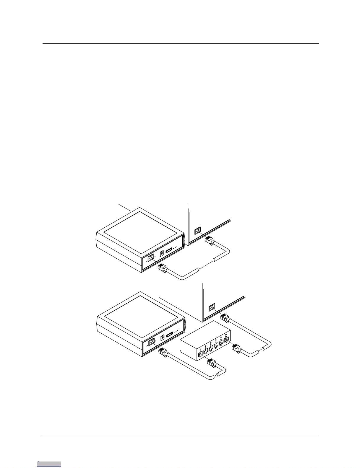
Figure QS-1 Connecting the computer
Direct connection options: Ethernet crossover cable (above), or Ethernet hub and two standard cables (below).
ASEK Main Board
Module
Personal computer
Ethernet
Crossover Cable
ASEK Main Board
Module
Personal computer
Ethernet
Hub
(2) Ethernet LAN
Standard Cable
Downloaded from Arrow.com.Downloaded from Arrow.com.Downloaded from Arrow.com.

Quick Start |
iv ASEK2-UG | Allegro® Sensor Evaluation Kit Technical Guide
2Solder the device-under-test (DUT) socket to the appropriate ASEK interface board, and
connect the ribbon cable between the interface board and the ASEK Main Board module
(Figure QS-2). (DUT connection without interface board is described later in this document.)
3CAUTION: ONLY USE the power supply included in the ASEK. Select a regional power plug
appropriate for the test facility, and swap it into the transformer body.Then connect the mini
plug to the ASEK module and connect the wall plug to the facility power mains.(Figure QS-3)
The ASEK powers-on immediately. Allow 30 seconds for the firmware to load.
4Open the Internet Web browser on the computer, and navigate to http://192.1.2.3. The ASEK
software opens as a Web page.
5Insert the DUT into the socket and use the ASEK software to perform demonstrations.
Figure QS-2 Connecting ribbon cable
For data transfer between ASEK Main Board module and an interface board with DUT socket.
Figure QS-3 Connecting power supply
Powers ASEK Main Board module, peripheral PCBs and a DUT for demonstration.
ASEK Main Board
Module
ASEK Interface Board
Connecting ribbon cable
to interface board
Mounting DUT
socket
Connecting ribbon cable to
ASEK Main Board module
ASEK Main Board
Module
Connect to power mains
Installing regional
power plug
Connecting power mini plug to
ASEK Main Board module
Insert DUT for
demonstration
Downloaded from Arrow.com.Downloaded from Arrow.com.Downloaded from Arrow.com.Downloaded from Arrow.com.

Allegro® Sensor Evaluation Kit Technical Guide v
Quick Start . . . . . . . . . . . . . . . . . . . . . . . . . . . . . . . . . . . . . . . . . . . . . . . . . . . . . iii
Using This Manual
Compatibilities . . . . . . . . . . . . . . . . . . . . . . . . . . . . . . . . . . . . . . . . . . . . . . . . . . . . . . . . . . . . . . . . . . . 2
Outline . . . . . . . . . . . . . . . . . . . . . . . . . . . . . . . . . . . . . . . . . . . . . . . . . . . . . . . . . . . . . . . . . . . . . . . . . 2
Audience . . . . . . . . . . . . . . . . . . . . . . . . . . . . . . . . . . . . . . . . . . . . . . . . . . . . . . . . . . . . . . . . . . . . . . . 3
Assumptions. . . . . . . . . . . . . . . . . . . . . . . . . . . . . . . . . . . . . . . . . . . . . . . . . . . . . . . . . . . . . . . . . . . . . 3
Relationship to Other Documents . . . . . . . . . . . . . . . . . . . . . . . . . . . . . . . . . . . . . . . . . . . . . . . . . . . . 3
Using PDF Hyperlinks . . . . . . . . . . . . . . . . . . . . . . . . . . . . . . . . . . . . . . . . . . . . . . . . . . . . . . . . . . . . . 3
Document Conventions . . . . . . . . . . . . . . . . . . . . . . . . . . . . . . . . . . . . . . . . . . . . . . . . . . . . . . . . . . . . 4
Getting Help. . . . . . . . . . . . . . . . . . . . . . . . . . . . . . . . . . . . . . . . . . . . . . . . . . . . . . . . . . . . . . . . . . . . . 4
1. Introduction
Applications . . . . . . . . . . . . . . . . . . . . . . . . . . . . . . . . . . . . . . . . . . . . . . . . . . . . . . . . . . . . . . . . . . .1 - 1
ASEK Software . . . . . . . . . . . . . . . . . . . . . . . . . . . . . . . . . . . . . . . . . . . . . . . . . . . . . . . . . . . . . . . .1 - 1
ASEK Hardware. . . . . . . . . . . . . . . . . . . . . . . . . . . . . . . . . . . . . . . . . . . . . . . . . . . . . . . . . . . . . . . .1 - 2
Allegro Kit Contents . . . . . . . . . . . . . . . . . . . . . . . . . . . . . . . . . . . . . . . . . . . . . . . . . . . . . . . . . . . . .1 - 2
System Requirements . . . . . . . . . . . . . . . . . . . . . . . . . . . . . . . . . . . . . . . . . . . . . . . . . . . . . . . . . . .1 - 6
Network Connections . . . . . . . . . . . . . . . . . . . . . . . . . . . . . . . . . . . . . . . . . . . . . . . . . . . . . . . .1 - 6
Work Area . . . . . . . . . . . . . . . . . . . . . . . . . . . . . . . . . . . . . . . . . . . . . . . . . . . . . . . . . . . . . . . . .1 - 6
User-Provided Equipment . . . . . . . . . . . . . . . . . . . . . . . . . . . . . . . . . . . . . . . . . . . . . . . . . . . .1 - 7
Safety. . . . . . . . . . . . . . . . . . . . . . . . . . . . . . . . . . . . . . . . . . . . . . . . . . . . . . . . . . . . . . . . . . . . . . . .1 - 9
2. Network Configuration
Using the Default IP Address. . . . . . . . . . . . . . . . . . . . . . . . . . . . . . . . . . . . . . . . . . . . . . . . . . . . . .2 - 1
Changing the IP Address. . . . . . . . . . . . . . . . . . . . . . . . . . . . . . . . . . . . . . . . . . . . . . . . . . . . . . . . .2 - 2
Configuring Simultaneous LAN Connection. . . . . . . . . . . . . . . . . . . . . . . . . . . . . . . . . . . . . . . . . . .2 - 4
3. ASEK Hardware
ASEK Main Board Module . . . . . . . . . . . . . . . . . . . . . . . . . . . . . . . . . . . . . . . . . . . . . . . . . . . . . . . .3 - 1
Data Link Configuration . . . . . . . . . . . . . . . . . . . . . . . . . . . . . . . . . . . . . . . . . . . . . . . . . . . . . . . . . .3 - 2
Power Supply Configuration. . . . . . . . . . . . . . . . . . . . . . . . . . . . . . . . . . . . . . . . . . . . . . . . . . . . . . .3 - 3
ASEK Interface PCBs . . . . . . . . . . . . . . . . . . . . . . . . . . . . . . . . . . . . . . . . . . . . . . . . . . . . . . . . . . .3 - 5
Linear Device (Output Pin Programming) Interface PCB . . . . . . . . . . . . . . . . . . . . . . . . . . . . .3 - 5
Switch or Latch Device (Supply Pin Programming) Interface PCB . . . . . . . . . . . . . . . . . . . . .3 - 7
Contents
Downloaded from Arrow.com.Downloaded from Arrow.com.Downloaded from Arrow.com.Downloaded from Arrow.com.Downloaded from Arrow.com.

Contents
vi Allegro® Sensor Evaluation Kit Technical Guide
On-Board DUT Sockets . . . . . . . . . . . . . . . . . . . . . . . . . . . . . . . . . . . . . . . . . . . . . . . . . . . . . . . . . .3 - 9
Off-Board DUT Socket Connections . . . . . . . . . . . . . . . . . . . . . . . . . . . . . . . . . . . . . . . . . . . . . . .3 - 10
DUT Connection Without Interface PCBs . . . . . . . . . . . . . . . . . . . . . . . . . . . . . . . . . . . . . . . . . . .3 - 11
Force/Sense Connections . . . . . . . . . . . . . . . . . . . . . . . . . . . . . . . . . . . . . . . . . . . . . . . . . . . . . . .3 - 12
4. DUT Programming
Setting Up . . . . . . . . . . . . . . . . . . . . . . . . . . . . . . . . . . . . . . . . . . . . . . . . . . . . . . . . . . . . . . . . . . . .4 - 1
Setting up for Programming. . . . . . . . . . . . . . . . . . . . . . . . . . . . . . . . . . . . . . . . . . . . . . . . . . . . . . .4 - 2
Programming Standard Linear Devices. . . . . . . . . . . . . . . . . . . . . . . . . . . . . . . . . . . . . . . . . . . . . .4 - 3
Preparing the Board and DUT . . . . . . . . . . . . . . . . . . . . . . . . . . . . . . . . . . . . . . . . . . . . . . . . .4 - 3
Performing Test and Programming . . . . . . . . . . . . . . . . . . . . . . . . . . . . . . . . . . . . . . . . . . . . .4 - 3
Programming 137x Linear Devices . . . . . . . . . . . . . . . . . . . . . . . . . . . . . . . . . . . . . . . . . . . . . . . . .4 - 4
Preparing the Board and DUT . . . . . . . . . . . . . . . . . . . . . . . . . . . . . . . . . . . . . . . . . . . . . . . . .4 - 4
Performing Test and Programming . . . . . . . . . . . . . . . . . . . . . . . . . . . . . . . . . . . . . . . . . . . . .4 - 5
Programming Switch or Latch Devices . . . . . . . . . . . . . . . . . . . . . . . . . . . . . . . . . . . . . . . . . . . . . .4 - 7
Preparing the Board and DUT . . . . . . . . . . . . . . . . . . . . . . . . . . . . . . . . . . . . . . . . . . . . . . . . .4 - 7
Performing Test and Programming . . . . . . . . . . . . . . . . . . . . . . . . . . . . . . . . . . . . . . . . . . . . .4 - 7
Programming with the Desktop Utility . . . . . . . . . . . . . . . . . . . . . . . . . . . . . . . . . . . . . . . . . . . . . . .4 - 8
Preparing the Board and DUT . . . . . . . . . . . . . . . . . . . . . . . . . . . . . . . . . . . . . . . . . . . . . . . . .4 - 8
Preparing the Desktop Utility . . . . . . . . . . . . . . . . . . . . . . . . . . . . . . . . . . . . . . . . . . . . . . . . . .4 - 9
Performing Test and Programming . . . . . . . . . . . . . . . . . . . . . . . . . . . . . . . . . . . . . . . . . . . .4 - 12
Using the 136X Utility. . . . . . . . . . . . . . . . . . . . . . . . . . . . . . . . . . . . . . . . . . . . . . . . . . . . . . . . . . .4 - 13
Preparing the Board and DUT . . . . . . . . . . . . . . . . . . . . . . . . . . . . . . . . . . . . . . . . . . . . . . . .4 - 14
Preparing the 136X Utility . . . . . . . . . . . . . . . . . . . . . . . . . . . . . . . . . . . . . . . . . . . . . . . . . . . .4 - 14
Performing Test and Programming . . . . . . . . . . . . . . . . . . . . . . . . . . . . . . . . . . . . . . . . . . . .4 - 16
5. ASEK Main Board Calibration
When to Calibrate . . . . . . . . . . . . . . . . . . . . . . . . . . . . . . . . . . . . . . . . . . . . . . . . . . . . . . . . . . . . . .5 - 1
Performing Calibrations . . . . . . . . . . . . . . . . . . . . . . . . . . . . . . . . . . . . . . . . . . . . . . . . . . . . . . . . . .5 - 1
Preparing the ASEK . . . . . . . . . . . . . . . . . . . . . . . . . . . . . . . . . . . . . . . . . . . . . . . . . . . . . . . . .5 - 2
Downloaded from Arrow.com.Downloaded from Arrow.com.Downloaded from Arrow.com.Downloaded from Arrow.com.Downloaded from Arrow.com.Downloaded from Arrow.com.

1
Figure QS-1 Connecting the computer.....................................................................................................................QS-iii
Figure QS-2 Connecting ribbon cable ......................................................................................................................QS-iv
Figure QS-3 Connecting power supply.....................................................................................................................QS-iv
Figure 1-1 ASEK System Configuration ...................................................................................................................... 1-3
Figure 2-1 ASEK software interface, Main page.......................................................................................................... 2-3
Figure 2-2 ASEK software interface, IP address setting page..................................................................................... 2-4
Figure 3-1 ASEK Main Board module, rear view......................................................................................................... 3-2
Figure 3-2 Direct connection options........................................................................................................................... 3-3
Figure 3-3 ASEK Power supply set............................................................................................................................. 3-4
Figure 3-4 Changing power supply prongs.................................................................................................................. 3-4
Figure 3-5 Linear device, output-pin programming PCB (PN 85-0329-101) layout..................................................... 3-6
Figure 3-6 Linear device, output-pin programming PCB (PN 85-0329-101) basic schematic..................................... 3-6
Figure 3-7 Layout of C2, CBLOW, socket on linear device (output pin programming) interface board......................... 3-7
Figure 3-8 Bipolar switch or latch device, supply-pin programming PCB (PN 85-0329-102) layout............................ 3-8
Figure 3-9 Bipolar switch or latch device, supply-pin programming PCB (PN 85-0329-102) basic schematic............ 3-8
Figure 3-10 Pre-designed DUT socket mounting ........................................................................................................ 3-9
Figure 3-11 Jumping unused GND terminals on the VCC programming PCB.......................................................... 3-10
Figure 3-12 ASEK Main Board ribbon cable header pin-out...................................................................................... 3-11
Figure 4-1 ASEK Interface, page for programming standard linear devices ............................................................... 4-3
Figure 4-2 ASEK Interface, page for programming A137x style linear devices........................................................... 4-5
Figure 4-3 ASEK page for switch/latch programming.................................................................................................. 4-7
Figure 4-4 ASEK Interface, opening page for the Desktop Utility downloads.............................................................. 4-9
Figure 4-5 Security confirmation box for the Desktop Utility download ..................................................................... 4-10
Figure 4-6 ASEK Desktop Utility interface................................................................................................................. 4-11
Figure 4-7 ASEK 136X Utility interface...................................................................................................................... 4-15
Figure 5-1 Board Calibration Utility page..................................................................................................................... 5-2
Figures
Downloaded from Arrow.com.Downloaded from Arrow.com.Downloaded from Arrow.com.Downloaded from Arrow.com.Downloaded from Arrow.com.Downloaded from Arrow.com.Downloaded from Arrow.com.

Allegro® Sensor Evaluation Kit Technical Guide | ASEK2-UG 2
Using This Manual
This chapter introduces the purpose and use of this document. It also includes information on con-
tacting Allegro® MicroSystems (Allegro) support groups. Information in this document is subject to
change without notice. For additional information, contact your local Allegro field service represen-
tative or sales representative, as described in this chapter.
Compatibilities
This guide describes the use of the Allegro Sensor Evaluation Kit (ASEK) Version 2, and applies to
the following release levels:
• Allegro Sensor Evaluation Kit firmwareandhardware compatiblewiththe ASEK-02Main Board
revision 1
In addition to these releases, certain additional configuration files contain information on specific
devices and configurations that may be updated from time to time for compatibility with new prod-
ucts. For information on updated configuration files, contact your local Allegro field service repre-
sentative.
The ASEK is designed to operate only with the power supply transformer supplied in the kit. Do not
use with any other transformer.
The network interface operates on IEEE 802.3, 10/100Base-T Ethernet
The ASEK kit and contents are lead (Pb) free and RoHS compliant.
Outline
The following sections are presented:
• Chapter 1, Introduction, provides a reference for the applications covered, kit parts list, system
requirements, user-supplied parts specifications, system electrical characteristics, and safety
considerations.
• Chapter2,NetworkConfiguration, describestheprocedure forconfiguringthe ASEKtoconnect
to the operator computer via LAN or by direct connection.
• Chapter 3, ASEK Hardware, describes the ASEK board, power supply, and connections.
• Chapter 4, DUT Programming, describes procedures for using the various programming and
evaluation tools provided in the ASEK software.
• Chapter 5, ASEK Main Board Calibration, describes the use of the Calibration board.
Downloaded from Arrow.com.Downloaded from Arrow.com.Downloaded from Arrow.com.Downloaded from Arrow.com.Downloaded from Arrow.com.Downloaded from Arrow.com.Downloaded from Arrow.com.Downloaded from Arrow.com.

Using This Manual | Audience
3ASEK2-UG | Allegro® Sensor Evaluation Kit Technical Guide
Audience
This guide is intended for:
• Qualified technicians and engineers who are employees of companies that purchase of the cor-
responding Allegro products.
• Computer network administrators of companies who purchase the kit.
• Allegro field applications engineers.
• Allegro design, sales, and support staff
Assumptions
Users of this guide should have a working knowledge of the Microsoft Windows operating system
for using certain of the software modules, Hall effect sensor technology, electronic test and mea-
surement techniques, electrical power supply operation, and have a knowledge of the application
being designed.
Relationship to Other Documents
This document replaces all previous user guides for the Allegro Sensor Evaluation Kit, version 2.
The data in this manual constitutes the available documentation on the ASEK-02 kit. The kit is
intended to be used as is, and Allegro does not support modifications to the kit, other than those
specified in this document.
Using PDF Hyperlinks
When viewed online as an electronic book in PDF format, the cross-references in the text, such
as: see Figure 1-1, are active hyperlinks. To go to the cited figure, table, or section, click the link
text. To do so, position the arrow-shaped pointer over the hyperlink text, and when it changes to a
pointing hand , click to go to the target.
In addition to the links embedded in the text, the page numbers in the Table of Contents and list of
figures are hyperlinks. Click the page number to go to the cited page.
The Adobe Acrobat viewer also provides an interactive set of links in the Bookmarks tab in the
Navigation pane. The Navigation pane is displayed by default, but if it has been closed in the
instance that you are using, in the Acrobat main menu, click View > Navigation Tabs > Book-
marks, or press the F4 key.
CAUTION: Check for the latest version of this manual, on the Allegro On-line Store
website at www.allegromicro.com.
Downloaded from Arrow.com.Downloaded from Arrow.com.Downloaded from Arrow.com.Downloaded from Arrow.com.Downloaded from Arrow.com.Downloaded from Arrow.com.Downloaded from Arrow.com.Downloaded from Arrow.com.Downloaded from Arrow.com.
Using This Manual | Document Conventions
Allegro® Sensor Evaluation Kit Technical Guide | ASEK2-UG 4
Document Conventions
The following document conventions are used throughout the documentation set.
Getting Help
A PDF version of this manual is available on the Allegro On-line Store website.
For additional information on the ASEK system or to report problems, contact your local Allegro
field applications engineering office.
Convention Description
Bold text Literal text appearing in the interface of the software product
Monospace text Text that is entered or returned by the software
Italic text When describing data input, a variable data placeholder (the text is replaced with
appropriate text for entry); in other contexts, text to be considered literally
[text | text]Optional fields, with the pipe ( | ) character indicating to select one of the alternatives
given within the brackets
{text, text} Mandatory fields, with the comma (,) character indicating to select one or more
choices within the braces
Information about potential loss of data
Additional information of interest
Information about potential hazard to operator or equipment
Downloaded from Arrow.com.Downloaded from Arrow.com.Downloaded from Arrow.com.Downloaded from Arrow.com.Downloaded from Arrow.com.Downloaded from Arrow.com.Downloaded from Arrow.com.Downloaded from Arrow.com.Downloaded from Arrow.com.Downloaded from Arrow.com.

Using This Manual | Getting Help
5ASEK2-UG | Allegro® Sensor Evaluation Kit Technical Guide
Downloaded from Arrow.com.Downloaded from Arrow.com.Downloaded from Arrow.com.Downloaded from Arrow.com.Downloaded from Arrow.com.Downloaded from Arrow.com.Downloaded from Arrow.com.Downloaded from Arrow.com.Downloaded from Arrow.com.Downloaded from Arrow.com.Downloaded from Arrow.com.

Allegro® Sensor Evaluation Kit Technical Guide | ASEK2-UG 1 - 1
Chapter 1
Introduction
Welcome to the Allegro Sensor Evaluation Kit (ASEK). The ASEK boards, together with the Web-
based firmware application, provide a powerful and flexible system for evaluation and program-
ming of Allegro Hall-effect sensors. The kit includes a calibration board that provides a rapid and
repeatable method for calibrating the ASEK Main Board.
Applications
The ASEK system is intended for use with field-programmable Hall effect devices offered by sale
by Allegro. This includes the following types of devices:
• 2-, or 3- or 4-wire switches or latches that are programmed using the supply pin
• 3-wire linear sensors that are programmed using the output pin
The firmware for the kit includes configuration data for specific Allegro devices that are supported
at the time of release of the kit. From time to time, as additional devices become available, the
firmware may be updated to adapt to those devices, and made available in updated versions of
this kit. Contact your local Allegro field applications engineering office for details on supported
devices.
The kit is intended for use as:
• a benchtop engineering tool for evaluating individual Allegro sensor devices; it can be used to
characterize and understand the performance of the various types of sensor devices
• calibrating field-programmable Allegro devices in small volumes; the device is ideal for charac-
terizing the effects of the various register value increments and for understanding and develop-
ing procedures for programming code streams for use on production systems
Additional device development kits for other Allegro devices may be available on the Allegro web-
site, www.allegromicro.com, by following the On-line Store link.
ASEK Software
The programs required to access and operate the ASEK are pre-installed as firmware on the Main
Board of the ASEK. The firmware falls into the following categories:
• Main Application. One graphical interface provides access to all functions, and it opens auto-
matically upon accessing the IP address of the ASEK Main Board. These functions are sum-
marized in the following items.
CAUTION: The ASEK system is intended for low-volume engineering applications. It is not
intended to be used in volume production environments, other than for system
development purposes.
Downloaded from Arrow.com.Downloaded from Arrow.com.Downloaded from Arrow.com.Downloaded from Arrow.com.Downloaded from Arrow.com.Downloaded from Arrow.com.Downloaded from Arrow.com.Downloaded from Arrow.com.Downloaded from Arrow.com.Downloaded from Arrow.com.Downloaded from Arrow.com.Downloaded from Arrow.com.

Introduction | ASEK Hardware
1 - 2 ASEK2-UG | Allegro® Sensor Evaluation Kit Technical Guide
• Board Configuration Utility. This module allows a network system administrator to change the
LAN address of the ASEK Main Board.
• Board Calibration Utility. This module allows the operator to calibrate the ASEK Main Board.
• DeviceDemonstratormodules.Thesearesimplifiedinterfaceapplicationsusedtoevaluateand
program the device under test (DUT). There are three demonstrator modules: for switches (2-
or 3-wire), for standard linear devices, and for linear devices with additional programming
modes (the 137x family).
• Desktop Utility. This module allows the operator to perform hands-on benchtop and in situ sys-
tem evaluations of the behavior of various Allegro field-programmable devices. It includes:
– Desktop Utility. This module provides an interface to sending and receiving data
from the ASEK.
– 136X Utility. This module provides a specific interface for working with linear
devices in the A136x family.
– Configuration File. This contains information about particular devices, used with
the Desktop and 136X utilities.
ASEK Hardware
The kit hardware consists of a module housing the main controller and system interface printed cir-
cuit board (PCB) assembly, with peripheral PCB assemblies that serve as interfaces for mounting
or connecting to DUT sockets. Interconnect cables and a multiregional power supply are also pro-
vided. The general layout of the ASEK system is shown in Figure 1-1 on page 1-3.
Allegro Kit Contents
Before opening the ASEK package, ensure that the necessary support items are available, as
described in System Requirements, on page 1-6. At the minimum, an ESD-resistant pad should be
available for placing the contents as they are unpacked.
The ASEK Board kit comprises several circuit board assemblies, with supporting elements, identi-
fied in Table 1-1.
When the package is received, immediately compare its contents to Table 1-1. If there are any
missing or damaged items, contact your local Allegro field applications engineering office immedi-
ately.
Downloaded from Arrow.com.Downloaded from Arrow.com.Downloaded from Arrow.com.Downloaded from Arrow.com.Downloaded from Arrow.com.Downloaded from Arrow.com.Downloaded from Arrow.com.Downloaded from Arrow.com.Downloaded from Arrow.com.Downloaded from Arrow.com.Downloaded from Arrow.com.Downloaded from Arrow.com.Downloaded from Arrow.com.
Introduction | Allegro Kit Contents
Allegro® Sensor Evaluation Kit Technical Guide | ASEK2-UG 1 - 3
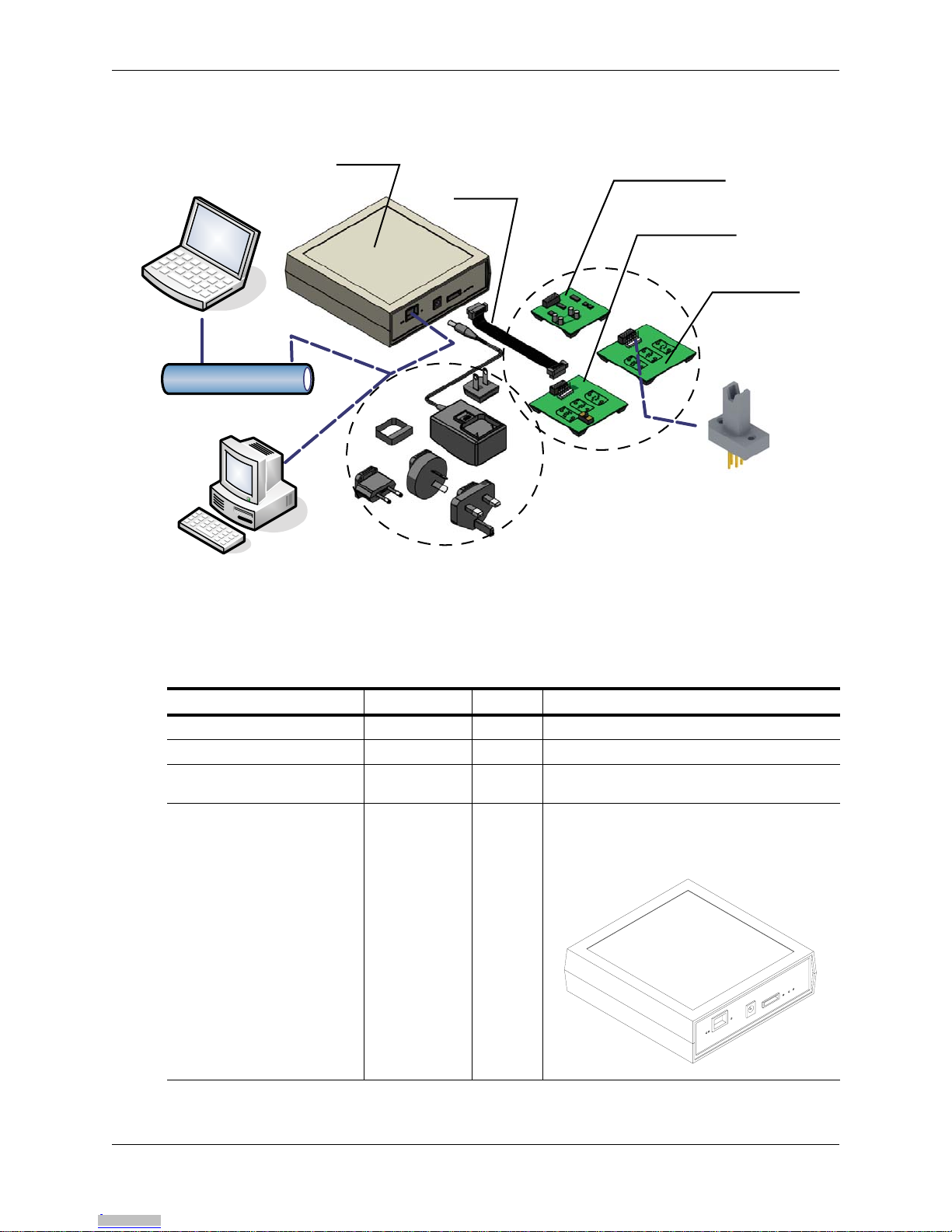
Figure 1-1 ASEK System Configuration
The system can operate over an Ethernet LAN or a direct-wired connection to the Main Board module by addressing the ASEK IP
address. The connection is compatible with common process control systems. A ribbon cable connection from the Main Board mod-
ule can be connected to either of the product interface boards or to the ASEK system calibration board.
Table 1-1 ASEK-02 Parts List
Item Part Number Quantity Description
Allegro Sensor Evaluation Kit ASEK-02 – Consisting of the components listed in this table
Application software N/A 1 Installed as firmware on the Main Board of the ASEK
Main Board module N/A 1 Primary demonstrator module consisting of the
following components
Protective Housing N/A 1
13 cm x 13 cm, 4 cm overall height approximately;
apertures for power supply socket, Ethernet socket,
peripheral interface cable socket; windows for power
and signal LEDs
Ethernet
Alternative operator
computer location
via Ethernet LAN
ASEK calibration
board assembly
ASEK ribbon cable for
connecting peripheral
PCBs individually
ASEK linear device
interface board
assembly
ASEK Main Board
module
ASEK power transformer
with regional adapters
Local operator
computer
location
ASEK switch/latch
device interface board
assembly
DUT sockets may be
soldered to PCBs or
remotely connected
Downloaded from Arrow.com.Downloaded from Arrow.com.Downloaded from Arrow.com.Downloaded from Arrow.com.Downloaded from Arrow.com.Downloaded from Arrow.com.Downloaded from Arrow.com.Downloaded from Arrow.com.Downloaded from Arrow.com.Downloaded from Arrow.com.Downloaded from Arrow.com.Downloaded from Arrow.com.Downloaded from Arrow.com.Downloaded from Arrow.com.

Introduction | Allegro Kit Contents
1 - 4 ASEK2-UG | Allegro® Sensor Evaluation Kit Technical Guide
Main Board 85-0329-001
Rev. 1
(Installed in
housing) 1
Main Board should only be operated inside of the
protective housing due to the heat generated by the
Ethernet interface board.
Firmware version is available using the ASEK
Desktop Utility.
Peripheral Connection
Ribbon cable 85-0329-300
(Installed on
housing) 1
10 cm length, with IDC male 14-pin ribbon cable
connector each end
Calibration Peripheral PCB 85-0329-100
Rev. 1
Calibration Board 1
5 cm x 5 cm, IDT female 14-pin ribbon cable header
(Molex 87831-1429), used for calibrating the ASEK
Main Board
Linear Device (Output Pin
Programmed) Demonstrator
Peripheral PCB
85-0329-101
Rev. 1
Socket Board 1
6.3 cm x 6.3 cm, IDT female 14-pin ribbon cable
header (Molex 87831-1429), 6-pin solid header
2.54 mm centers (Molex 22-11-2062), 3 device
socket areas; used for Allegro linear Hall devices
Table 1-1 ASEK-02 Parts List (Continued)
Item Part Number Quantity Description
Downloaded from Arrow.com.Downloaded from Arrow.com.Downloaded from Arrow.com.Downloaded from Arrow.com.Downloaded from Arrow.com.Downloaded from Arrow.com.Downloaded from Arrow.com.Downloaded from Arrow.com.Downloaded from Arrow.com.Downloaded from Arrow.com.Downloaded from Arrow.com.Downloaded from Arrow.com.Downloaded from Arrow.com.Downloaded from Arrow.com.Downloaded from Arrow.com.

Introduction | Allegro Kit Contents
Allegro® Sensor Evaluation Kit Technical Guide | ASEK2-UG 1 - 5
Switch Device (Supply Pin
Programmed) Demonstrator
Peripheral PCB
85-0329-102
Rev. 2
VCC
Programming
Socket Board
1
6.3 cm x 6.3 cm, IDT female 14-pin ribbon cable
header (Molex 87831-1429), 6-pin solid header
2.54 mm centers (Molex 22-11-2062), 3 DUT socket
areas; switch for programming pin selection; used for
Allegro switch or latch Hall devices
External DCPower Supply Module
(Wall-mount) 85-0329-400 1
6 cm x 4 cm, 4 cm overall height approximately;
5 VDC 1.2 A 5%, 90-264 VAC, 5.5 mm diameter
center positive, mini plug cable, 4 regional power
plug adapters, contact protective shroud
Table 1-1 ASEK-02 Parts List (Continued)
Item Part Number Quantity Description
Downloaded from Arrow.com.Downloaded from Arrow.com.Downloaded from Arrow.com.Downloaded from Arrow.com.Downloaded from Arrow.com.Downloaded from Arrow.com.Downloaded from Arrow.com.Downloaded from Arrow.com.Downloaded from Arrow.com.Downloaded from Arrow.com.Downloaded from Arrow.com.Downloaded from Arrow.com.Downloaded from Arrow.com.Downloaded from Arrow.com.Downloaded from Arrow.com.Downloaded from Arrow.com.

Introduction | System Requirements
1 - 6 ASEK2-UG | Allegro® Sensor Evaluation Kit Technical Guide
System Requirements
This kit includes hardware and software, and requires additional user-supplied equipment to oper-
ate properly.
Network Connections
The ASEK must be operated by a computer, but it is designed to allow the computer to be located
either at the test bench using a direct wired connection, or to be located remotely, connected by
Ethernet LAN. The ASEK includes an Ethernet port.
Although operation of the ASEK for device demonstrations can be performed either locally or via
LAN, changing of the IP address of the ASEK must be performed via direct connection (see
Changing the IP Address, on page 2-2).
For direct connection to the operator computer, the following alternatives can be used:
• A CAT5e 0.9 m Ethernet crossover cable between the ASEK and the operator computer.
• Ethernet standard LAN cable connected to a local separately-powered Ethernet hub, with a
second Ethernet cable connecting from the hub to the operator computer.
• For computers that do not have an Ethernet interface, either type of cable can be connected to
the computer by means of a wired USB Ethernet adapter.
• Wireless, serial port, and parallel port protocols are not supported.
Work Area
The work area should allow the printed circuit board assemblies, as well as the DUT (device under
test) to be protected from ESD (electrostatic discharge) at all times. Standard temperature and
humidity levels should be maintained to suppress ESD.
The boards should be placed on a level work surface, free of objects and obstructions. The sur-
face should be located at an ergonomic height.
The work area should allow the printed circuit board assemblies to be located as near as practica-
ble to each other. For data and power connections between the ASEK Main Board and the periph-
eral PCBs, the ASEK includes a ribbon cable that is approximately 10 cm in length. It is
recommended that the supplied cable always be used as the interface to the peripheral PCBs, and
for best results, it should not be extended in length.
Downloaded from Arrow.com.Downloaded from Arrow.com.Downloaded from Arrow.com.Downloaded from Arrow.com.Downloaded from Arrow.com.Downloaded from Arrow.com.Downloaded from Arrow.com.Downloaded from Arrow.com.Downloaded from Arrow.com.Downloaded from Arrow.com.Downloaded from Arrow.com.Downloaded from Arrow.com.Downloaded from Arrow.com.Downloaded from Arrow.com.Downloaded from Arrow.com.Downloaded from Arrow.com.Downloaded from Arrow.com.
Introduction | System Requirements
Allegro® Sensor Evaluation Kit Technical Guide | ASEK2-UG 1 - 7
User-Provided Equipment
Certain equipment and materials must be provided by the user. These are described in the follow-
ing tables.
Table 1-2 User-provided Equipment: Computer and Network Peripherals
Item Description
Computer
CPU and memory: processing is performed primarily on the ASEK Main
Board
Hard disk space: if the Desktop Utility is used, that requires under 100 kB
Interfaces: Ethernet port with RJ45 female connector, or USB 2.0 or
higher female port that can accommodate an Ethernet adapter
Computer monitor, color; 1024 x 768 pixels minimum recommended for
optimum viewing of user interface application
Mouse and keyboard
Operating system
Supports a graphical user interface
Web browser application installed
For use of the Desktop Utility module, Microsoft Windows and .NET
Framework 2.0 installed
LAN
Direct connection (required for changing IP address of ASEK):
Ethernet crossover cable, RJ45 male/male CAT5e, or
Separately-powered Ethernet hub connected between ASEK and
operator computer by 2 standard Ethernet connection cables
LAN connection:
IEEE 802.3, 10/100Base-T Ethernet LAN with standard Ethernet
connection cable
Table 1-3 User-provided Equipment: Programming Tasks
Item Description
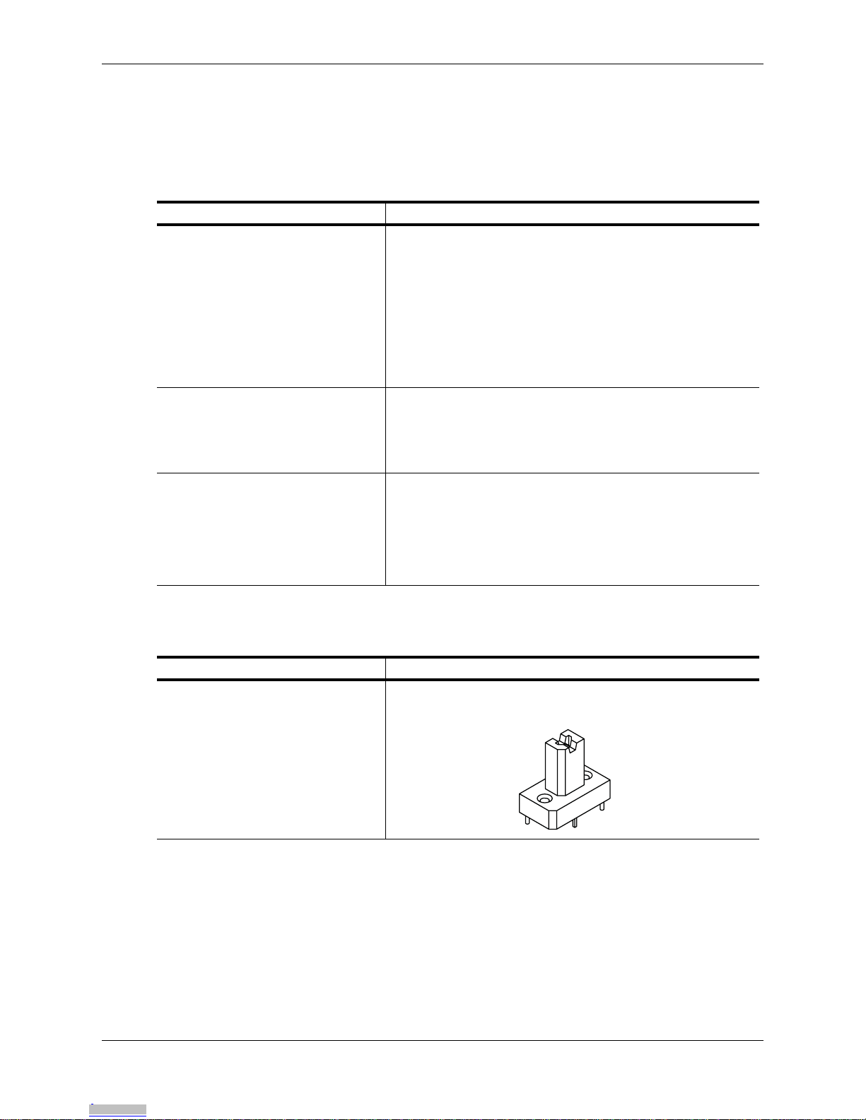
DUT sockets
DUT sockets for standard device package types are available directly
from Azimuth Electronics (www.azimuth-electronics.com). Otherwise, as
required by the package type of the Allegro DUT.
Downloaded from Arrow.com.Downloaded from Arrow.com.Downloaded from Arrow.com.Downloaded from Arrow.com.Downloaded from Arrow.com.Downloaded from Arrow.com.Downloaded from Arrow.com.Downloaded from Arrow.com.Downloaded from Arrow.com.Downloaded from Arrow.com.Downloaded from Arrow.com.Downloaded from Arrow.com.Downloaded from Arrow.com.Downloaded from Arrow.com.Downloaded from Arrow.com.Downloaded from Arrow.com.Downloaded from Arrow.com.Downloaded from Arrow.com.

Introduction | System Requirements
1 - 8 ASEK2-UG | Allegro® Sensor Evaluation Kit Technical Guide
Off-Board Connection
For connection from an ASEK interface PCB to a user-provided DUT
socket that is mounted off-board, connection to on-board Molex 6373
series 6-pin solid header (such as Molex 6471 series Crimp Terminal
Housing 22-01-2025, accepts Molex 4809 series Crimp Terminals 22-30
AWG, such as 85-50111), shielded cable with 4 to 8 conductors and length
as short as possible.
For direct connection from ASEK Main Board to a user-provided DUT
socket (without ASEK interface board), connection to on-board Molex
87833-1420 14-pin ribbon cable PCB header, 2 mm centers (such as
Molex 87568-1494 IDT cable-to-board receptacle).
Ethernet Crossover Cable
Used for IP address setting. 0.9 m or shorter, male RJ45 connectors both
ends; CAT5e crossover cable; compatible with Ethernet 10/100Base-T.
Soldering Equipment DUT sockets acquired from Azimuth Electronics are manually soldered
onto the peripheral PCBs. Additional filter components may be required to
be soldered to the PCBs for certain applications.
DUT bypass capacitor As required by application, see DUT datasheet for rating.
Recommended maximum rating of 0.1 µF to avoid creating instability in
ASEK system, and minimum 50 V.
Table 1-3 User-provided Equipment: Programming Tasks (Continued)
Downloaded from Arrow.com.Downloaded from Arrow.com.Downloaded from Arrow.com.Downloaded from Arrow.com.Downloaded from Arrow.com.Downloaded from Arrow.com.Downloaded from Arrow.com.Downloaded from Arrow.com.Downloaded from Arrow.com.Downloaded from Arrow.com.Downloaded from Arrow.com.Downloaded from Arrow.com.Downloaded from Arrow.com.Downloaded from Arrow.com.Downloaded from Arrow.com.Downloaded from Arrow.com.Downloaded from Arrow.com.Downloaded from Arrow.com.Downloaded from Arrow.com.

Introduction | Safety
Allegro® Sensor Evaluation Kit Technical Guide | ASEK2-UG 1 - 9
Safety
In order to prevent damage to the operator or to the kit or DUT, only qualified electronics techni-
cians or individuals with equivalent training should operate the product.
Follow the safety precautions required by local laws and regulations, and by the procedures of
your company.
The following specific warnings are not meant to be exclusive, or to limit the application of normal
safety precautions in any way:
DUT blowing capacitor
As required by application, see DUT datasheet for rating. Capacitor must
be capable of withstanding higher voltages required for blowing solid state
fuses internal to the DUTs while programming them.
This capacitor may be required to be inserted and removed at different
stages of programming, and a socket should be used. On the ASEK linear
DUT interface PCB, an optional socket is installed with 2.54 mm and 5.08
mm pitch holes, accepts capacitor leads 0.38 mm to 0.64 mm in diameter
and 2.54 mm to 3.71 mm in length (Aries series 0513 collet socket).
CAUTION: Only use the power supply provided with the ASEK. Do not substitute any
other power supply, or damage to the ASEK electronics may occur.
CAUTION: Always take precautions to avoid ESD before handling boards. This includes:
using ESD resistant clothing and gloves, and personal conductive straps, properly
connected to an earth ground. The work surface should be on an ESD-resistant pad, and
the operator should be standing or sitting on an ESD-resistant mat.
Table 1-3 User-provided Equipment: Programming Tasks (Continued)
Downloaded from Arrow.com.Downloaded from Arrow.com.Downloaded from Arrow.com.Downloaded from Arrow.com.Downloaded from Arrow.com.Downloaded from Arrow.com.Downloaded from Arrow.com.Downloaded from Arrow.com.Downloaded from Arrow.com.Downloaded from Arrow.com.Downloaded from Arrow.com.Downloaded from Arrow.com.Downloaded from Arrow.com.Downloaded from Arrow.com.Downloaded from Arrow.com.Downloaded from Arrow.com.Downloaded from Arrow.com.Downloaded from Arrow.com.Downloaded from Arrow.com.Downloaded from Arrow.com.
Table of contents
Other Allegro Motherboard manuals


Popular Motherboard manuals by other brands

ABACOM Technologies
ABACOM Technologies RX-AUDIO-24-D manual

MSD Ignition
MSD Ignition 7550 installation instructions

VIA Technologies
VIA Technologies K8T890 user manual

Asus
Asus ROG MAXIMUS Z690 FORMULA manual

ASROCK Rack
ASROCK Rack EP2C612D16-2L2T Quick installation guide

Lattice Semiconductor
Lattice Semiconductor USB3-GbE VIP I/O Board user guide

NXP Semiconductors
NXP Semiconductors S12ZVM-EWP quick start guide

Advantech
Advantech PCM-9579 Startup manual

TELink
TELink B91 quick start guide

Biostar
Biostar G965 MICRO 775 Setup manual

Connect Tech
Connect Tech Photon NVIDIA Jetson AI Camera Platform user guide

Sapphire Audio
Sapphire Audio PI-A9RX480 user manual


