manuals.online logo
Brands
  1. Home
  2. •
  3. Brands
  4. •
  5. ALLEN & HEATH
  6. •
  7. Mixer
  8. •
  9. ALLEN & HEATH XONE:V6 Operating and installation instructions

ALLEN & HEATH XONE:V6 Operating and installation instructions

Other ALLEN & HEATH Mixer manuals

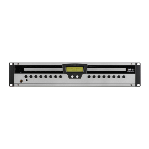
ALLEN & HEATH iDR Series User manual

ALLEN & HEATH

ALLEN & HEATH iDR Series User manual

ALLEN & HEATH XONE:96 User manual

ALLEN & HEATH

ALLEN & HEATH XONE:96 User manual

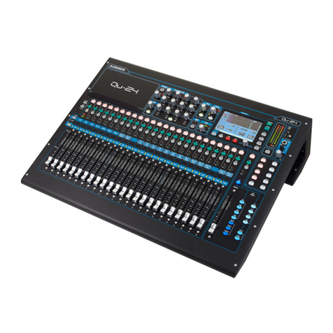
ALLEN & HEATH Qu-16 User instructions

ALLEN & HEATH

ALLEN & HEATH Qu-16 User instructions

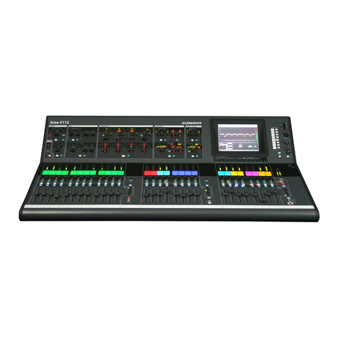
ALLEN & HEATH iLIVE User manual

ALLEN & HEATH

ALLEN & HEATH iLIVE User manual

ALLEN & HEATH GR1 User manual

ALLEN & HEATH

ALLEN & HEATH GR1 User manual

ALLEN & HEATH GR05 User manual

ALLEN & HEATH

ALLEN & HEATH GR05 User manual

ALLEN & HEATH ZED 12 FX User manual

ALLEN & HEATH

ALLEN & HEATH ZED 12 FX User manual

ALLEN & HEATH Xone: S2 User manual

ALLEN & HEATH

ALLEN & HEATH Xone: S2 User manual

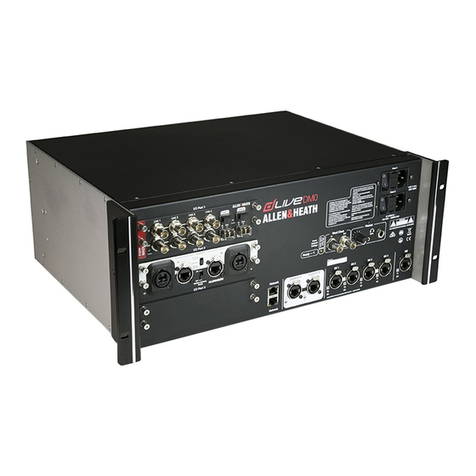
ALLEN & HEATH dLive DM0 MixRack User manual

ALLEN & HEATH

ALLEN & HEATH dLive DM0 MixRack User manual

ALLEN & HEATH iDR MixRack User manual

ALLEN & HEATH

ALLEN & HEATH iDR MixRack User manual

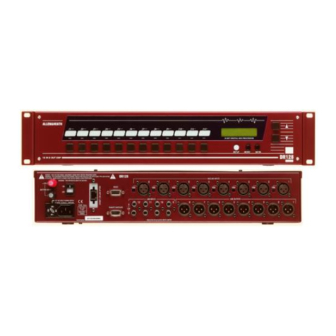
ALLEN & HEATH DR128 User manual

ALLEN & HEATH

ALLEN & HEATH DR128 User manual

ALLEN & HEATH iLIVE User manual

ALLEN & HEATH

ALLEN & HEATH iLIVE User manual

Popular Mixer manuals by other brands

Oster FPSTSM2710 instruction manual

Oster

Oster FPSTSM2710 instruction manual

Aviom A-16II user guide

Aviom

Aviom A-16II user guide

Varimixer V30K Spare part and operation manual

Varimixer

Varimixer V30K Spare part and operation manual

Kohler Stillness K-T954 installation guide

Kohler

Kohler Stillness K-T954 installation guide

Wolf Gourmet WGSM300 Use & care guide

Wolf Gourmet

Wolf Gourmet WGSM300 Use & care guide

Team International TEAM MS 17 operating instructions

Team International

Team International TEAM MS 17 operating instructions

MULTIQUIP Whiteman WM45E Operation and parts manual

MULTIQUIP

MULTIQUIP Whiteman WM45E Operation and parts manual

KitchenAid KSM7581BZ0 Instructions and recipes

KitchenAid

KitchenAid KSM7581BZ0 Instructions and recipes

Jay-Lor 5050 owner's manual

Jay-Lor

Jay-Lor 5050 owner's manual

privileg MJ-BL1051W user manual

privileg

privileg MJ-BL1051W user manual

Fakir CULINA CHEF user manual

Fakir

Fakir CULINA CHEF user manual

Termozeta Bellacucina Instruction booklet

Termozeta

Termozeta Bellacucina Instruction booklet

Thinky ARE-250 instruction manual

Thinky

Thinky ARE-250 instruction manual

Midas XL4 manual

Midas

Midas XL4 manual

bianco PURO 4 manual

bianco

bianco PURO 4 manual

better chef IM-815WC Use and care book

better chef

better chef IM-815WC Use and care book

Buffalo CP921 instruction manual

Buffalo

Buffalo CP921 instruction manual

ARX BarMIX owner's manual

ARX

ARX BarMIX owner's manual

manuals.online logo
manuals.online logoBrands
  • About & Mission
  • Contact us
  • Privacy Policy
  • Terms and Conditions

Copyright 2025 Manuals.Online. All Rights Reserved.

ALLEN&HEATH
WARNING – HIGH VOLTAGES
Power Supply Unit (PSU) work should only
be carried out by qualified personnel.
We recommend that you use an approved Allen Heath
service centre for all power supply work.
Please contact your local Allen Heath distributor for more details.
http://www.allen-heath.com/
SERVICE INFORMATION
Publication AP4976
2xonev6_ap4976_4.doc
Introduction
This publication provides technical information on servicing the Allen & Heath Xone:V6 rotary club mixer,
Xone:V6 EQ Isolator and Xone:V6 Crossfader modules. Included are internal layout drawings, block
diagrams and circuit schematics with board layouts. Whilst we believe this information to be reliable we
do not assume responsibility for inaccuracies. We also reserve the right to make changes in the interest of
further product development.
Additional Resources
Allen & Heath web site www.allen-heath.com Product information
Technical downloads
Distribution contacts
Companycontacts
Technical support [email protected] See web for local contact
Xone:V6 user guide AP4975 Operating instructions
Performance specification
User jumper link options
Meter bulb replacement
Xone:V6 options user guide AP5377 Operating instructions
Performance specification
All Valve option AP5295 Fitting instructions
Xone:V6 Service Information
Issue status: xonev6_ap4976_4.doc
Print date: 04 November 2004
Copyright © 2004 Allen & Heath. All rights reserved
Manufactured in the United Kingdom by Allen & Heath
Kernick Industrial Estate, Penryn, Cornwall, TR10 9LU, UK
http://www.allen-heath.com
xonev6_ap4976_4.doc 3
Servicing Precautions – General Notes
Service personnel: Service work should be carried out by technically qualified service personnel only.
Mains power is dangerous and can kill. Do not attempt to work on a linear or switched
mode power supply if you are not suitably qualified to do so. Do not attempt to repair
surface mount circuit assemblies unless you are suitably qualified and have the
necessary facilities to do so. Replacement circuit assemblies can be ordered.
Service facilities: Ensure a suitably sized work surface is available. Ensure this is clear of dirt, debris
and obstructions which may damage the equipment surfaces. Ensure adequate
lighting. Use the correct tools for the job and ensure they are in good working order.
Ensure all workshop safety requirements are adhered to.
Service information: Check that you have all the information you need before starting the service job. Refer
to the Allen & Heath web site or contact Allen & Heath technical support for details on
the latest information. Full technical information can be downloaded from the web site
Distributor Zone (password required).
Mains power: Connect the equipment to mains power only of the type described in the user guide
and marked on the rear panel. The power source must provide a good ground
connection. Ensure you always use an isolation transformer when working on any
mains power supply unit.
Mains cord and fuse: Use the correct power cord as supplied with the equipment. Do not remove or tamper
with the ground connection in the power cord. Heed the Important Mains Plug Wiring
Instructions printed in the user guide if it is necessary to rewire the mains cord.
Always replace the equipment mains fuse with the correct type and rating as
described in the user guide and marked on the equipment panel.
Opening the unit: Switch off and remove the mains power cord before opening the equipment. Ensure
all power supply covers and safety shields are in place before applying power with the
unit open for diagnostic fault finding.
Closing the unit: Before finishing, check the quality and accuracy of the service work carried out.
Remove any dirt or debris as this may cause equipment failure in the future. Ensure all
assemblies, harnesses and connectors are correctly aligned and plugged in. Ensure
that jumper settings and control configurations are correctly set according to the
requirements of the customer.
Testing the unit: Before operating the equipment, read and adhere to the Important Safety Instructions
printed in the user guide. Test that the service work has been successfully carried out.
Shipping the unit: Use adequate packing such as the original packaging or purpose designed flight case
if you need to ship the unit. To avoid injury to yourself or damage to the equipment
take care when lifting, moving or carrying the equipment.
Servicing Notes – Xone:V6
User maintenance: There are several user configurable jumper links inside. These are described in the
user guide together with instructions on how to change the default settings.
Technology: The Xone:V6 uses conventional thru-hole PCB technology with high grade discrete
transistor and valve audio circuits. It has an external hybrid linear, switched mode
power supply which should be serviced only by suitably qualified personnel.
Operation: The Xone:V6 is an audiophile rotary club mixer. To ensure optimum performance and
reliability it should be connected and operated as described in the user guide.
Fault finding: Refer to the system block diagram and circuit drawings to follow through the signal
path during fault diagnosis. Replace suspected faulty components only with those
specified by Allen & Heath. The use of lower grade alternatives may degrade the
performance. Ensure the RCA phono insert jumper links are pressed fully in if fitted. If
a fault with the power unit is found, make sure it has been positioned according to the
instructions in the user guide when installed. VU meter bulb replacement is described
in the user guide.
4xonev6_ap4976_4.doc
Contents Log
XONE:V62 – Historical Change Log ..........................xonev6_ap4976_4.pdf
Internal Layout drawing ............................................... xonev6_layout_1.pdf
........................................................................ xonev6_options_layout_1.pdf
Surface and Main Parts..................................................xonev6_parts_3.pdf
..........................................................................xonev6_options_parts_1.pdf
System Block Diagram ....................................xonev6_blockdiagram_2.pdf
Input PCB ............................................. xonev6_003-050_090_input_1.1.pdf
Master PCB ..................................................xonev6_003-051_master_2.pdf
Mic PCB.......................................................... xonev6_003-052_mic_1.1.pdf
Booth PCB..................................................... xonev6_003-053_booth_1.pdf
Phones PCB................................................xonev6_003-054_phones_1.pdf
Meter PCB ......................................................xonev6_003-055_meter_1.pdf
Valve PCB.....................................................xonev6_003-056_valve_1.1.pdf
Power Supply PCB........................................xonev6_003-057_power_2.pdf
All Valve Option PCB ........................xonev6_003-130_allvalveoption_1.pdf
Crossfader Option PCB ..................xonev6_options_003-154_xfader_2.pdf
EQ Isolator Option PCB ................... xonev6_options_003-156_eqiso_2.pdf
Engineering Change Notes ........................................... xonev6_ecns_1.pdf
PSU Uprating Technical Bulletin ......................xonev6_psu_uprating_1.pdf
xonev6_ap4976_4.doc 5
XONE:V6 – Historical Change Log
The following list identifies historical changes to the XONE:V6. The effective dates, serial
numbers and related change note documentation are included for reference to help identify
the correct issue circuit boards and components. Whilst we believe this information to be
reliable we do not assume responsibility for inaccuracies. We also reserve the right to make
changes in the interest of further product development.
Assembly Description
From Serial
Number Date Change Note
Number
003-051/057 Master PCB & Power PCB up-issues - 14/11/02 812
003-050 Input 1-4 PCB inductor replacement 047453 25/11/02 814
003-052 Mic PCB op-amp change 047939 06/01/03 821
003-047/048 Pot and jack grounding (crinkle
washers) 047939 09/01/03 827
003-057 PSU PCB - uprated bridge rectifier - 11/03/04 985
003-057 IEC Mains Filter with Nutserts - 29/03/04 998
003-
051/052/054
/154
Jack Socket - change of manufacturer
& part number - see parts diagram - 28/07/04 1054
xonev6_layout_1.doc Sheet 1 of 1
Product ............................ XONE:V6/100
........................................XONE:V6/110
........................................XONE:V6/120
........................................XONE:V6/220
........................................XONE:V6/240
DC Cable Assembly ................. 002-583
Pack Assembly......................... 003-045
Main Assembly ......................... 003-046
Panel Assembly Front .............. 003-047
Chassis Assembly .................... 003-048
PSU Assembly ......................... 003-049
Cue Switch Cable Assembly .... 003-089
Fader Assembly ....................... 003-109
VU Meter Assembly.................. 003-110
Input 1-4 PCB........................... 003-050
Input 5-6 PCB........................... 003-090
Master PCB .............................. 003-051
Mic PCB ................................... 003-052
Booth PCB................................ 003-053
Phones PCB............................. 003-054
Meter PCB................................ 003-055
Valve PCB ................................ 003-056
Power PCB............................... 003-057
All Valve Option PCB ............... 003-130
XONE:V6 FRONT
PHONES PCB
003-054
MIC PCB
003-052
INPUT 5-6 PCBs
003-090
VALVE PCB
003-056
INPUT 1-4 PCBs
003-050
METER PCB
003-055
MASTER PCB
003-051
BOOTH PCB
003-053
xonev6_options_layout_1.doc Sheet 1 of 1
Product ................... XONE:V6-XFADER
Crossfader Main Assembly ...... 003-153
Pack Assembly......................... 003-157
Crossfader PCB ....................... 003-154
Product ...................... XONE:V6-EQISO
EQ Isolator Main Assembly ...... 003-155
Pack Assembly......................... 003-157
EQ Isolator PCB ....................... 003-156
AL2159
CROSSFADER Front
003-154
CROSSFADER CUE PCB
FRONT PANEL
AI4222
003-154
AL3822
AL3822
EQ ISOLATOR Front FRONT PANEL
003-156
AG5383-2 PCB
AL3822 003-156
EQ ISOLATOR PCB
AL5494
AI4905 AI4964 AI4905
AL5494
AL5370 AL5370
A
L4907
AL3817
AI4964
003-154
xonev6_parts_3.doc Sheet 1 of 1
XONE:V6 Surface Parts
MAINS INPUT
V.AC
MAINS INPUT
FUSE
MADE IN ENGLAND BY ALLEN & HEATH LIMITED
S/No
250V
T
T2.5AL
M3
x
4 SCREW
A
B3852
+4dBuBOOTH MASTER OUT
ALLEN&HEATH PSU
ONLY USE CORRECT
INPUT
DC POWER
FOR UNBALANCED OPERATION USE JACK OUTPUTS
R
PHONES 2
L
WARNING!
DO NOT SHORT PIN 2 OR PIN 3 TO GROUND.
FOR BALANCED CONNECTION ONLY.
R
L
MIC INSERT
MIC TO BOOTH
MIC INPUT
CUE DC LINK
RECORD
L
-10dBV
GND
EXT CUE INPUT
-OUT - IN
1
XLR
+OUT
2
+IN
2
GND
TIP
RING
TIP +
RING -
LINE IN/OUT
1
INSERT
R
L
MASTER OUT
-2dBu
R
RING RETURN
TIP SEND MASTER
INSERT
&ALLEN HEATH
MADE IN ENGLAND BY ALLEN & HEATH LIMITED
WARNING - THIS APPARATUS M UST BE EARTHED. REFER TO USER GUIDE BEFORE CONNECTING SUPPLY.
TO REDUCE THE RISK OF FIRE OR ELECTRIC SHOCK DO NOT EXPOSE THIS APPARATUS TO RAIN OR MOISTURE.
RTNRTN
NO USER SERVICEABLE PARTS INSIDE. REFER SERVICING TO QUALIFIED SERVICE PERSONNEL.
SND
AVIS: RISQUE DE CHOC ELECTRIQUE - NE PAS OUVRIR
SND
RTN RTN RTNRTN
SND SND SND SND
R
LINE
A
LR
LINE
A
LR
A
L
A
PHONO/
LINE
L
A
PHONO/
LINE
RL
A
PHONO/
LINE
R
PHONO/
LINE
LR
SLIMLINE JACK SOCKET
A
L2048
PLASTIC JACK NUT AL8133
2BA TERMINAL POST
A
L8106
LATCHING SWITCH
A
L0162
FEMALE D-TYPE CONNECTOR AL2259
INCLUDING FIXINGS
STEREO JACK SOCKET & NUT
A
L5903
M9 CRINKLE WASHER AB5191
DUAL PHONO AL0577 FEMALE XLR
A
L4982 QUAD PHONO SOCKET
A
L4977
4
x
5/16 SCREW
A
B2810
7WAY SOCKET AL3893 M3
x
6 SCREW
A
B0072
M2.5
x
8 XLR SCREW AB5140
MALE XLR
A
L4983
10
18
3
63
0
10
610
18
3
63
0
10
610
18
3
63
0
10
610
18
3
63
0
10
610
18
3
63
0
10
610
18
3
63
0
10
6
CHANNEL 5
ON
INPUT 5
LINE A
LEVEL
60
OFF
HI-PASSHI-PASSHI-PASSHI-PASS
6
CHANNEL 1
1
Rotary Faders 010
45
2
3
CUE
ON
OFF
CHANNEL 3
CUE
5
11 99
CHANNEL 2
10
00
5
4
3
82
7
CUE
ON
OFF
4
6
8
7
2
3
ON
OFF
11 99
CHANNEL 4
10 010
CUE
4
6
8
7
2
3
ON
OFF
4
6
5
8
7
2
3
LINE
200
40
30Hz
60
100
LEVEL
PHONO
INPUT 1 INPUT 3
100
LEVELLEVEL
600Hz
400
500 40
30Hz
60
100
600Hz
500
400
40
30Hz
60
200
INPUT 2
LINE
PHONO PHONO
LEVEL
30Hz
400
500
600Hz
40
60
200
400
600Hz
40
500
100 200
INPUT 4
LINE PHONO LINE
HI-PASSHI-PASS 100Hz80Hz 120Hz
9
8
10
199
010
CHANNEL 6
010
6
5
82
73
CUE
6
5
4
8
7
CUE
ON
OFF
MASTER
MIC
10
1
0
2
4
3
6
5
9
8
ON
OFF
7
1
0
2
+6
MASTER EQ
-6
4
3
-15
1
10
9
82
BOOTH
011
+15
6
5
73
4
-6
5
7
+6
6
11
PHONES
0
1
2
10
9
MIX
CUE
4
3
56
7
8
RIGHT MIX LEVEL
10kHz
600Hz30Hz
500
400
100 200
40
30Hz
60
600Hz
400
500
200
100
LEVEL
LINE A
LINE B LINE B
INPUT 6
10kHz
+6-6 -15
2.5kHz
+15 -6 +6
LEFT MIX LEVEL
TONE
LF
CUE/MIX
HF
LARGE KNOB CAP
A
J5014
10KAx2 POT 003-109
M9 CRINKLE WASHER AB5191
M3
x
8 SCREW
A
B0073
MOMENTARY CHROMED SWITCH 003-089
MEDIUM KNOB CAP
A
J5015
18MM 250KCx4 POT AI4905
VU METER 003-110
S
PARE 12V METER B
U
LB
A
D
5
1
98
STEREO JACK SOCKET
A
L4749
NUT & WASHER
AB5240
SINGLE POLE SWITCH AL4907
CLEAR GREEN LED
A
E5146
CLEAR BLUE LED AE5147
CLEAR RED LED AE5145
18MM 20KBx2 POT
A
I4964
METER FACIA
A
A4866
LED WINDOW PLATE AA4990
LED PLATE AA4777
SMALL KNOB CAP AJ5016
9MM 20KAx2 POT AI4963
2-POLE SWITCH
A
L4906
M2.5x6 SCREW
A
B4979
CAUTION: FOR CONTINUED PROTECTION AGAINST RISK OF FIRE REPLACE FUSE
DO NOT OBST RUCT VENTILATION OPENINGS.
DO NOT OPEN. NO USE R SERVICEABLE PARTS INSIDE.
THIS APPARATUS MUST BE EARTHED BY THE POWER CORD.
ATTENTION: REMPLACER LE FUSIBLE AVEC UN DES MEMES CARACTERISTIQUES.
COUPER L' ALIMENTATION AVANT D E CHANGER LE FUSIBLE.
WITH SAME TYPE AN D RATING. DISC ONNECT SUPPLY BEFORE CHANGING FUSE.
HYBRID LINEAR PSU
HEATH
PIN 2. +30V 1A
PIN 4. A GND
PIN 5. D GND
PIN 3. A GND
PIN 1. +6.3V 2A
DC POWER
ALLEN&
CAUTION
WARNING: TOREDUCE THE RISK OF ELECTRICSHOCK
DO NOT EX POSE THIS APPARATU S TO RAIN OR MOISTURE.
AVIS: RISQUE DE CHOC ELECTRIQUE - NE PAS OUVRIR.
M3
x
6 SCREW
A
B0071
PSU COVER
A
A4972
PSU CHASSIS
A
A4971
POWER RAIL MONITORS
+6.3V
DC POWER OUT
+30V -30V PROTECT
M3
x
6 SCREW
A
B0071
7WAY PLUG
A
L3891
M3x6 SCREW AB0072
CLEAR GREEN LED
A
E5146
CLEAR RED LED
A
E5145
FUSE HOLDER AL3178
2.5A FUSE AL0311
M3x10 SCREW
A
B0076
M3 NYLOCK NUT AB0102
MAINS IEC
A
L3458 M3x6 SCREW
A
B0072
MAINS SWITCH
A
L2047
M2.5x12 SCREW AB4980
18MM 10KAx2 POT
A
I4904
PHONO SHORTING PLUG
AL4396
PHONO SOCKET JUMPER
A
L4978
ECC82 VALVE AE5139
ALL VALVE OPTION XONE:V6-
V
ALVE