Allen-Bradley Bulletin 1694 User manual

User Manual
Bulletin 1694 Electronic circuit protection for 24V DC
(Cat xxxx-xxx)
WARNING: Electrostatically sensitive sub-assemblies can be destroyed by voltages far below the human perception threshold. These voltages already occur if you touch a component
or electrical terminals of a sub-assembly without being electrostatically discharged. The damage of a sub-assembly caused by an overvoltage is often not immediately
recognised, but will be noticed only after a longer operating time.
Mounting or actuation of the 1694 connector arm must only be effected at dead-voltage. For start-up the 1694 connector arm must be closed.
Device to be installed, operated and maintained by trained personnel only.
The device can’t be serviced or repaired.
To secure device properly against unintended access, product shall be mounted in locked cabinet.
Notes
Features
Basic trip curve and schematic diagram 1694-PM
Bulletin 1694 Electronic circuit protection for 24V DC
• Connection to a higher or not reliably disconnected voltage can cause hazardous conditions or damages
• Only the intended circuit protectors must be used
• The technical data of the circuit protectors used have to be observed
• The entire power distribution system must only be installed by qualified personnel
• Only after expert installation must the device be supplied with power
• After tripping of the circuit protector and before reset, the cause of the failure (short circuit or overload) must be remedied
• The national standards have to be observed for installation and selection of feed and return cables.
• Combination of supply modules, circuit protection and power distribution
• Selective load protection by means of electronic trip curve
• No accessories required for connecting the components
• Width per channel only 12.5 mm (1-channel) or 6.25mm (2-channel)
• Integral fail-safe element, adjusted to current rating
• Switching capacitive loads up to 20,000 µF (at IN > 6A)
• Manual ON/OFF/reset momentary switch
• Clear status indication by means of LED and auxiliary contact (1694-PF supply module)
• Connection via push-in terminals
• 1694-PMx available in Class 2 version with nominal currents: 1A, 2A, 3A, 4A
Bulletin 1694 Electronic Circuit Protection is a modular solution with a max. system capacity of 40A. The protection modules come in a fix current rating
in a range from 1A…10A. Designed for 24V DC circuits, the 1694 provides comprehensive protection against short circuit and overcurrent conditions
while allowing for inrush current.
trip time in seconds
times rated current trip curve
1.000
100
10
1
0,1
0,01
0,001
0,8 1,0 1,2 1,4 1,6 1,8 2,0 2,2 2,4 2,6 2,8 3,0 3,2 3,4 IKS
Schematic diagram
blade fuse
semiconductor
4 A
LINE
4 A
LOAD
Do not open device’s enclosure.

Technical data (T
amb
= +23 °C, U
B
= DC 24 V)
1694-PM Circuit Protection Module
Operating voltage
U
B
DC 24 V (min. 18 V, max. 30 V)
(no battery-buffered applications)
Reverse polarity protection Yes, without load
Influence of ambient temperature
on overload trip and load current
warning limit
see temperature factor table
Leakage current in load circuit
in OFF condition
typically <1 mA
Voltage drop in load circuit
at IN for 1694-PM
between LINE+ and LOAD+
• IN: 1A (CL2) typically 180 mV
• IN: 2A (CL2) typically 110 mV
• IN: 3A typically 120 mV
• IN: 3A- CL2 typically 130 mV
• IN: 4A typically 115 mV
• IN: 4A- CL2 typically 180 mV
• IN: 6A typically 170 mV
• IN: 8A typically 160 mV
• IN: 10A typically 180 mV
Overload disconnection (IOL)
with trip times (tOL)
short circuit trip time (tKS)
typically IOL: INx 1.05 tOL: 3s
typically IOL: INx 1.35 tOL: 0.5s
typically IOL: INx 2.00 tOL: 0.1s
typically IOL: INx 2.50 tOL: 0.012s
typically at (IKS) tKS: 0.002s 1
see time/current characteristics
Rated current IN
1694-PM1 (1-channel)
1694-PM2 (2-channel)
current ratings:
1 A, 2 A, 3 A, 4 A, 6 A, 8 A, 10 A
1A/1A, 2A/2A, 3A/3A, 4A/4A, 6A/6A
Visual status indication
by means of LED:
Load circuit
Load current warning limit (IWLimit)
1694-PM
Hysteresis
Status of auxiliary contact is not affected by 90% load current warning
1 depending on power source
Green: Load circuit connected
flashing
orange Load current warning limit reached
green:
orange: Overload or short circuit until disconnection
red: After disconnection (trip condition) due to overload or short circuit
after undervoltage release of operating voltage in ON condition with autoreset
OFF: Device switched off by means of ON/OFF
Non Illuminated momentary switch or no operating voltage
typically 0.9 x IN
typically 5%
Closed current I0
1694-PM1 (1-channel)
1694-PM2 (2-channel)
in ON condition:
typically 5 mA
typically 8 mA
User Manual: Bulletin 1694 Electronic circuit protection for 24V DC
2
Publication1694-IN002D-EN-E -June 2020 DIR 10005220601 (Version 03)

Fail-safe element
integrated fuse
Adjusted to the corresponding rated current IN
• IN: 1A (CL2) fail-safe IN: 1A
• IN: 2A (CL2) fail-safe IN: 2A
• IN: 3A fail-safe IN: 3.15A
• IN: 3A-CL2) fail-safe IN: 4A
• IN: 4A fail-safe IN: 4A
• IN: 4A-CL2 fail-safe IN: 4A
• IN: 6A fail-safe IN: 6.3A
• IN: 8A fail-safe IN: 8A
• IN: 10A fail-safe IN: 10A
Low voltage monitoring
of operating voltage
OFF at typically UB< 16.0 V
ON at typically UB> 19.0 V
Hysteresis typically 2 V with automatic OFF and ON operation
Disconnection of the load circuit • manually on the device with the ON/OFF momentary switch
• after an overload / short circuit disconnection with storage (no automatic reset)
• temporarily at undervoltage
• at no operating voltage
Switching on the load circuit
- Momentary switch ON/OFF
- Apply operating voltage
Unit can only be switched on when operating voltage was applied
The device re-starts with the last stored condition.
Reset function A blocked load output (blocked by overload / short circuit) can be reset or switched
on manually by the momentary ON/OFF switch (LED button).
Free-wheeling circuit external free-wheeling circuit at inductive load (rating according to load) is recommended.
Parallel connection
of several load outputs not permitted
Capacitive loads
(Depending on: cable attenuation,
power supply used, load current
and current rating)
at IN: 1A DC24V up to 5,000µF
at IN: 2A, 3A DC24V up to 10,000µF
at IN: 4A DC24V up to 12,000µF
at IN: > 6A DC24V up to 20,000µF
ON delay
- with power ON
- when switching on via ON/OFF
momentary switch
- after an undervoltage
channel 1: typically 100ms (1694-PM)
channel 2: typically 200ms (1694-PM)
channel 1: typically 5 ms
channel 2: typically 100 ms
channel 1: typically 5 ms
channel 2: typically 5 ms
Publication1694-IN002D-EN-E -June 2020 DIR 10005220601 (Version 03)
User Manual: Bulletin 1694 Electronic circuit protection for 24V DC
3

General Data
Conformity and approvals for 1694-PM with 1694-PF
Ambient temperature (Tamb) -25°...+60 °C (without condensation, cf. EN 60204-1)
Storage temperature -30°...+70 °C
Vibration resistance 3 g, test to IEC 60068-2-6 test Fc
Degree of protection
Operating area 1694-PM:
IEC 60529, DIN VDE 0470
IP30
EMC requirements
(EMC Directive, CE Logo)
Emitted interference: EN 61000-6-3
Noise immunity: EN 61000-6-2
Insulation co-ordination
(IEC 60934)
0.5 kV / pollution degree 2
Dielectric strength max. DC 30 V (load circuit)
Insulation resistance
(OFF condition)
n/a, only electronic disconnection
Modules mountable side by side
2Rockwell Automation recommends to use ferrules for smaller diameter cables.
3Class 2 only for Protection Modules
max. 36 channels allowed. Total current value shall be below 40 Amps.
(sample case: 36 channels refer to 1 Amp nominal current channels)
Dimensions (h x w x d) 12.5 x 80 x 98.5 mm
Weight approx. 60 g
Conformity CE Marking
RoHS compliant
China RoHS
WEEE
Morocco EMC
At the End of its life, this equipment should be collected separately from any unsorted municipal waste.
Approvals UL 2367 RA File # E350272 current rating range:1A… 10A
UL 1310 RA File # E350272 current rating range:
NEC Class2 3 1A, 2A, 3A, 4A
cULus508RA File # E56639 current rating range:1A… 10A
listed
Terminals
Push-in terminal PT 2.5
wire stripping length
LOAD+
0.14mm2 to 2.5mm2, flexible
AWG24 – AWG14 str.2
8mm to 10mm
Mounting temperature +5°… +60°C
Publication1694-IN002D-EN-E -June 2020 DIR 10005220601 (Version 03)
User Manual: Bulletin 1694 Electronic circuit protection for 24V DC
4
Humidity: 96 hrs / 95% RH RH/40 °C to IEC 60068-2-78-Cab climate class 3K3 to EN 60721
Corrosion
Only 1694-DM and 1694-PF
accessories
96hrs. in 5% salt mist to IEC 60068-2-11 test Ka

Typical time/current characteristic (T
amb
= +23 °C, UB = DC 24 V)
Temperature factor / continuous duty
Temperature factor table:
The time/current characteristic depends on the ambient temperature. In order to determine the max. load current,
please multiply the current rating with the temperature factor and consider the factor for side-by-side mounting.
ISC - short circuit current
Please note
- When mounted side-by-side, the devices can carry max. 80 % of their rated load or a different rating has to be selected.
- With high temperatures, the load current warning threshold “warn limit typically 0.9 x IN” will be reduced in accordance
with the temperature factor.
- Selection of current rating of the circuit protector ≤ rating of power supply.
1694-IN002D-EN-E -June 2020 (Version 03)PublicationDIR 10005220601
User Manual: Bulletin 1694 Electronic circuit protection for 24V DC
5
ambient temperature [°C]
0
10
23
40
50
60
temperature factor
1
1
1
0.95
0.90
0.85
1000
100
trip time in seconds
times rated current
10
1
0.1
0.01
0.001
0.8 1 1.2 1.4 1.6 1.8 2 2.2 2.4 2.6 2.8 3 ISC

Dimensions 1694-…
General recommendation for all 1694 modules installation.
Small opening above the screwdriver insert (marked as 2.1 and 2.2) = voltage measuring point.
Larger opening under the screwdriver insert (marked as LOAD +) = wire connection area.
Screwdriver for installation: blade-style screwdriver size 1 for smaller Push-in terminal (PT 2.5) inserts.
Mounting position: horizontal mounting position is preferred.
Publication1694-IN002D-EN-E -June 2020 DIR 10005220601 (Version 03)
User Manual: Bulletin 1694 Electronic circuit protection for 24V DC
6
Marker
1−channel2−channel
Button for ON / OFF or Reset
with integrated status indication (LED)
DC24V
1694-PM1
Contact arm
Operating area
Instalation area
CAT 1694−PMxyy−zzz SER X
Allen-Bradley
Protection Module xxxA xxx
snap−on socket for DIN rail EN 60715−35x7.5
2.1 2.2 2.1 2.1 2.12.2
LOAD + LOAD + LOAD + LOAD +
DC24V
Class 2
xA
xA
xA
xA xAxA
1694-PM2
DC24V
Class 2
1694-PM1
DC24V
1694-PM2

Product selection list - 1694-PMx
Bulletin 1694. Power Feed 1694-PFx and Distribution Modules 1694-DMx
Notes
Technical data (T
amb
= +23 °C, U
B
= DC 24 V)
General data - common for 1694-PFx / 1694-DMx
Power Feed 1694-PFx: Power Feed Module receives the DC 24 V supply voltage, e.g. from a switched mode power supply,
and distributes it to the mounted circuit protectors via the integral connector arm of the 1694-PM.
(The potential-free auxiliary contact in the 1694-PFA1244 indicates any detected failures through the circuit protector,
e.g. to the superordinate control unit (CPU).)
Distribution Modules 1694-DMx: For terminal multiplication to add multiple wires for + and – 24VDC
Please refer to notes section for Electronic circuit protection for 24V DC
Publication1694-IN002D-EN-E -June 2020 DIR 10005220601 (Version 03)
User Manual: Bulletin 1694 Electronic circuit protection for 24V DC
7
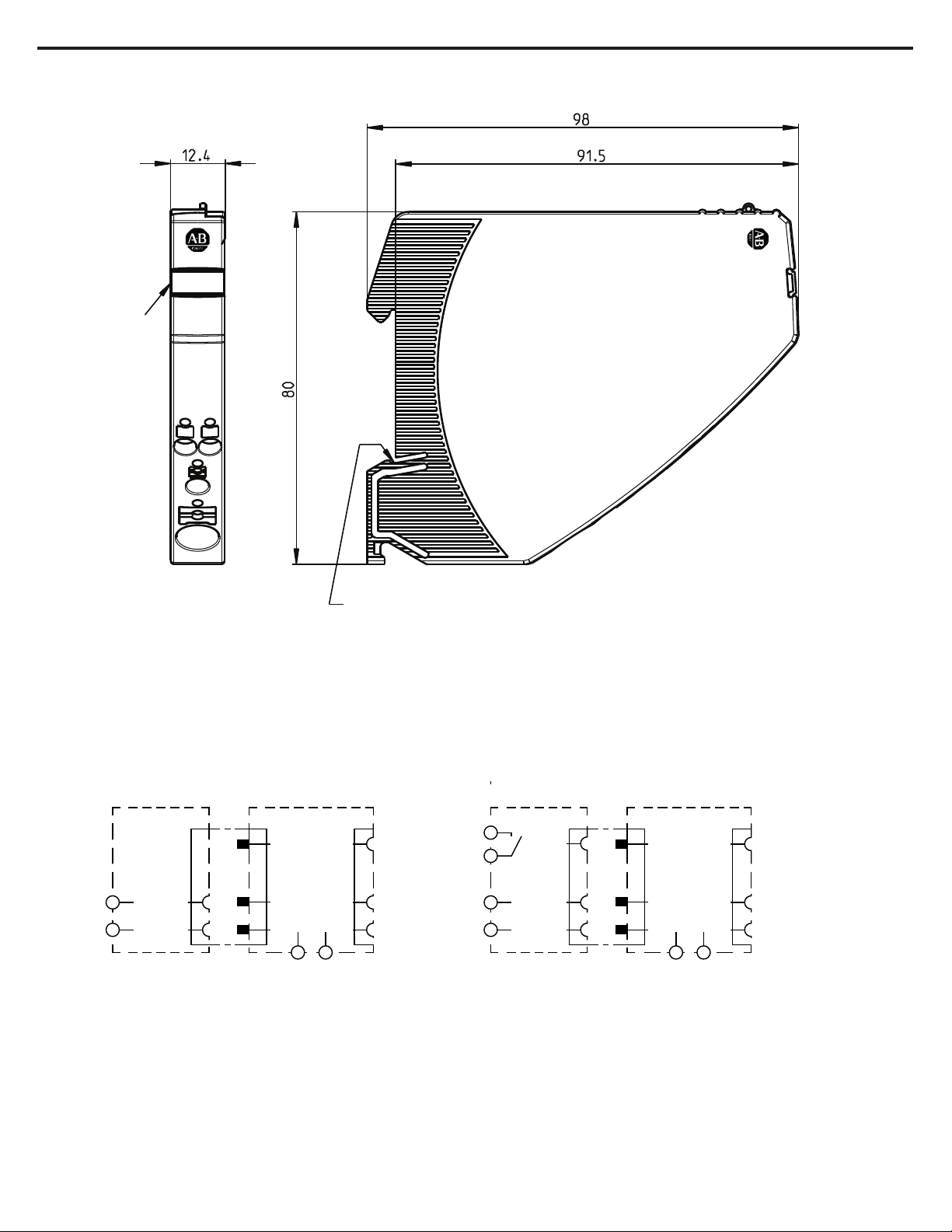
Mounting method symmetrical rail to EN 60715-35x7.5
Ambient temperature (Tamb) -25°...+60 °C (without condensation, cf. EN 60204-1)
Storage temperature -30°...+70 °C
Mounting temperature +5°… +60°C
Humidity: 96 hrs / 95% RH RH/40 °C to IEC 60068-2-78-Cab climate class 3K3 to EN 60721
Corrosion
Only 1694-DM and
1694-PF accessories
96hrs. in 5% salt mist to IEC 60068-2-11 test Ka
Catalog Code
Descripon
1694-PM110
Electronic Circuit Protecon, Protecon Module, 1-Channel, Fix Current, In 10A
1694-PM11
Electronic Circuit Protecon, Protecon Module, 1-Channel, Fix Current, In 1A
1694-PM11-CL2
Electronic Circuit Protecon, Protecon Module, 1-Channel, Fix Current, In 1A, Class 2
1694-PM12
Electronic Circuit Protecon, Protecon Module, 1-Channel, Fix Current, In 2A
1694-PM12-CL2
Electronic Circuit Protecon, Protecon Module, 1-Channel, Fix Current, In 2A, Class 2
1694-PM13
Electronic Circuit Protecon, Protecon Module, 1-Channel, Fix Current, In 3A
1694-PM13-CL2
Electronic Circuit Protecon, Protecon Module, 1-Channel, Fix Current, In 3A, Class 2
1694-PM14
Electronic Circuit Protecon, Protecon Module, 1-Channel, Fix Current, In 4A
1694-PM14-CL2
Electronic Circuit Protecon, Protecon Module, 1-Channel, Fix Current, In 4A, Class 2
1694-PM16
Electronic Circuit Protecon, Protecon Module, 1-Channel, Fix Current, In 6A
1694-PM18
Electronic Circuit Protecon, Protecon Module, 1-Channel, Fix Current, In 8A
1694-PM211
Electronic Circuit Protecon, Protecon Module, 2-Channels, Fix Current, 1A, 1A
1694-PM211-CL2
Electronic Circuit Protecon, Protecon Module, 2-Channels, Fix Current, 1A, 1A, Class 2
1694-PM222
Electronic Circuit Protecon, Protecon Module, 2-Channels, Fix Current, 2A, 2A
1694-PM222-CL2
Electronic Circuit Protecon, Protecon Module, 2-Channels, Fix Current, 2A, 2A, Class 2
1694-PM233
Electronic Circuit Protecon, Protecon Module, 2-Channels, Fix Current, 3A, 3A
1694-PM233-CL2
Electronic Circuit Protecon, Protecon Module, 2-Channels, Fix Current, 3A, 3A, Class 2
1694-PM244
Electronic Circuit Protecon, Protecon Module, 2-Channels, Fix Current, 4A, 4A
1694-PM244-CL2
Electronic Circuit Protecon, Protecon Module, 2-Channels, Fix Current, 4A, 4A, Class 2
1694-PM266
Electronic Circuit Protecon, Protecon Module, 2-Channels, Fix Current, 6A, 6A

Data for Power Feed Module 1694-PFx
Data for Distribution Module 1694-DMx
Publication1694-IN002D-EN-E -June 2020 DIR 10005220601 (Version 03)
User Manual: Bulletin 1694 Electronic circuit protection for 24V DC
8
Vibration resistance 3 g, test to IEC 60068-2-6 test Fc
Degree of protection
terminal area 1694-PF, 1694-DM:
IEC 60529, DIN VDE 0470
IP20
EMC requirements
(EMC Directive, CE Logo)
Emitted interference: EN 61000-6-3
Noise immunity: EN 61000-6-2
Insulation co-ordination
(IEC 60934)
0.5 kV / pollution degree 2
Dielectric strength max. DC 30 V (load circuit)
Dimensions
Operational Current
Operating voltage UB
Dimensions (h x w x d)
Weight approx.
Max. 20 A in total. Max. 10 A per terminal
0V - DC 24V (0 ... 30 V)
12.5 x 80 x 98.5 mm
60 g
12.5 x 80 x 98 mm
Operating voltage UBDC 24 V (min. 18 V, max. 30 V)
(no battery-buffered applications)
Reverse polarity protection Yes, without load
Closed current I0normal condition: typically 10 mA (min. 6,5 mA; max. 11,8 mA)
Auxiliary contact
potential-free
only in 1694-PFA1244
max. DC 30 V/0.5 A, min. 10 V/1 mA
Group signalling Si terminal:
Si (13) / Si (14)
Normal condition:
Auxiliary contact N/O
Auxiliary contact closed
Trip condition: coming from all protection modules
- when ON, load output ON
- when OFF, load output OFF
auxiliary contact open
Coming from one or more protection modules
- after disconnection due to overload or short circuit
- after undervoltage release of operating voltage in ON condition with auto reset
- at no operating voltage UBin supply module
Insulation coordination
0.5 kV / pollution degree 2
For 1694-PF3L4C, 1694-PF2L4S: 0.8 kV / pollution degree 2
Operating current IB
Dimensions (h x w x d)
1694-PFx: Max. 40 A
12.5 x 80 x 98 mm
0.5 kV / pollution degree 2
For 1694-DM1L2, 1694-DM2L2: 0.8 kV / pollution degree 2

Terminals 1694-PFx: 0 V / Si 13 / Si 14
Terminals 1694-DMx: LOAD+, 1694-DM3G2: 0V
Terminals 1694-DM and 1694-PF
Terminals 1694-PFx: LINE+1, 1694-PF3G4: 0V
User Manual: Bulletin 1694 Electronic circuit protection for 24V DC
9
Push-in terminal PT 10
wire stripping length
4Rockwell Automation recommends to use ferrules for smaller diameter cables
0.5mm2 to 10mm2, flexible
AWG20 – AWG8 str.4
18mm
Push-in terminal PT 2.5
wire stripping length
5Rockwell Automation recommends to use ferrules for smaller diameter cables
0.14mm2 to 2.5mm2, flexible
AWG24 – AWG14 str. 5
8mm to 10mm
Push-in terminal PT 2.5
wire stripping length
5Rockwell Automation recommends to use ferrules for smaller diameter cables
0.14mm2 to 2.5mm2, flexible
AWG24 – AWG14 str. 5
8mm to 10mm
Dimensions (h x w x d) 12.5 x 80 x 98.5 mm
Weight approx. 60 g
Approvals: 1694-PF3L4C, 1694-PF1G4, 1694-PF3G4:
UL 1059, RA File # E40735
1694-PF2L4S:
UL 2367, RA File # E350272
cULus508listed, RA File # E56639
1694-DM1L2, 1694-DM2L2, 1694-DM3G2:
UL 1059, RA File # E40735
At the End of its life, this equipment should be collected separately from any unsorted municipal waste.
1694-IN002D-EN-E -June 2020 (Version 03)PublicationDIR 10005220601
Conformity 1694-DM* CE Marking
RoHS compliant
China RoHS
WEEE
1694-PF1G4,
1694-PF3L4C
CE Marking
RoHS compliant
China RoHS
WEEE
1694-PF1244,
1694-PF2L4S,
1694-PFA1244
CE Marking
RoHS compliant
China RoHS
WEEE
Morocco EMC

Dimensions: 1694-PF1244 Power Feed Left Mount
Schematic diagram: 1694-PF1244 (with 1694-PM). Left Mount
Type: 1694-PF1244 Type: 1694-PFA1244
User Manual: Bulletin 1694 Electronic circuit protection for 24V DC
10
The meaning of diagram is symbolic (there is electrical connection between output and input connections
for Line +1 and 0V done by semiconductor element).
Snap−on socket for DIN rail EN 60715−35x7.5
CAT 1694−PF1244 SER X
Allen-Bradley
Power Feed 40A
Marker
0V
LINE + 1
DC24V
40A
1694-PF1
LOAD+ 2.1 | (2.2)
max. 16 pcs
1694-PF 1694-PM
0V
LINE+1
LOAD+ 2.1 | (2.2)
max. 16 pcs
1694-PF 1694-PM
0V
13
14
LINE+1
Publication1694-IN002D-EN-E -June 2020 DIR 10005220601 (Version 03)

Dimensions: 1694-PF3L4C Power Feed. Centre/Right Mount, LINE Connected
Schematic diagram: 1694-PF3L4C. Centre/Right Mount , LINE Connected
User Manual: Bulletin 1694 Electronic circuit protection for 24V DC
11
0V
LINE+1
COM
ADDR
LINE+1 0V
View: X
View: X
CAT 1694−PF3L4C SER X
Allen-Bradley
Power Feed 40A LC
Contact arm
snap−on socket for DIN rail EN 60715−35x7.5
Marker
0V
LINE + 1 LINE + 1
DC24V
40A
1694-PF3
View without connector arm contact via connector arm
contact via connector arm
0V
Publication1694-IN002D-EN-E -June 2020 DIR 10005220601 (Version 03)

Dimentions: 1694-PF2L4S Power Feed Center Mount, LINE Separated
Schematic diagram: 1694-PF2L4S Power Feed Center Mount, LINE Separated
User Manual: Bulletin 1694 Electronic circuit protection for 24V DC
12
View: X
View: X
CAT 1694−PF2L4S SER X
Allen-Bradley
Power Feed 40A LS
Contact arm
snap−on socket for DIN rail EN 60715−35x7.5
Marker
0V
LINE + 1 LINE + 1
DC24V
40A
1694-PF2
View without connector arm contact via connector arm
contact via connector arm
0V
0V
COM
ADDR
LINE+1 0V
Publication1694-IN002D-EN-E -June 2020 DIR 10005220601 (Version 03)

Dimensions: 1694-DM1L2 Distribution Load 10 Terminals, 1xLINE, 9xLOAD, Imax 20A
Schematic diagram: 1694-DM1L2 Distribution Load, 10 Terminals, 1xLINE, 9xLOAD, Imax 20A
User Manual: Bulletin 1694 Electronic circuit protection for 24V DC
13
max. 10A / terminal
2.5
2.4
2.3
2.2
2.1
2.10
2.9
2.8
2.7
2.6
0V
LINE+1
COM
ADDR
View: X
CAT 1694−DM1L2 SER X
Allen-Bradley
Distribution Load
View without connector arm
Contact arm
snap−on socket for DIN rail EN 60715−35x7.5
Marker
LOAD +
LOAD +
DC24V
20A
1694-DM1
2.5
2.4 2.9
2.4 2.9
2.3 2.8
2.3 2.8
2.2 2.7
2.2 2.7
2.1 2.6
2.1 2.6
2.10
2.5 2.10
contact via connector arm
View: X
1694-IN002D-EN-E -June 2020 (Version 03)PublicationDIR 10005220601

Dimensions: 1694-DM2L2 Distribution Load, 10 Terminals, 2xLINE separated, 4xLOAD each, Imax 20A
Schematic diagram: 1694-DM2L2 Distribution Load, 10 Terminals, 2xLINE separated, 4xLOAD each, Imax 20A
User Manual: Bulletin 1694 Electronic circuit protection for 24V DC
14
View: X
CAT 1694−DM2L2 SER X
Allen-Bradley
Distribution Load
View without connector arm
Contact arm
snap−on socket for DIN rail EN 60715−35x7.5
Marker
LOAD +
LOAD +
DC24V
20A
1694-DM2
2.5
2.4 2.9
2.4 2.9
2.3 2.8
2.3 2.8
2.2 2.7
2.2 2.7
2.1 2.6
2.1 2.6
2.10
2.5 2.10
contact via connector arm
View: X
max. 10A / terminal
2.5
2.4
2.3
2.2
2.1
2.10
2.9
2.8
2.7
2.6
0V
LINE+1
COM
ADDR
max. 10A max. 10A
Publication1694-IN002D-EN-E -June 2020 DIR 10005220601 (Version 03)

Dimensions: 1694-PF1G4 Power Feed GND, 0V Ground, Imax 40A
Schematic diagram: 1694-PF1G4 Power Feed GND, 0V Groud, Imax 40A
User Manual: Bulletin 1694 Electronic circuit protection for 24V DC
15
The meaning of diagram is symbolic (there is electrical connection between output and input connections
for Line +1 and 0V done by semiconductor element).
1694-PF
-GND-
1694-DM
1694-PF
-GND-
0V
View: X
CAT 1694−PF1G4 SER X
Allen-Bradley
Power Feed GND
View: X
snap−on socket for DIN rail EN 60715−35x7.5
Marker
0V
DC 0-24V
40A
1694-PF1
0V
contact via connector arm
GND − coding notch
Publication1694-IN002D-EN-E -June 2020 DIR 10005220601 (Version 03)

Dimensions: 1694-DM3G2 Distribution GND, 10 Terminals, Ground, Imax 20A
Schematic diagram: 1694-DM3G2 Distribution GND, 10 Terminals, Ground, Imax 20A
User Manual: Bulletin 1694 Electronic circuit protection for 24V DC
16
View: X
View: X
CAT 1694−DM3G2 SER X
Allen-Bradley
Distribution GND
Contact arm
snap−on socket for DIN rail EN 60715−35x7.5
Marker
0V
DC 0-24V
20A
1694-DM3
3.5
3.4
3.3
3.2
3.1
3.10
3.9
3.8
3.7
3.6
3.5
3.4
3.3
3.2
3.1
3.10
3.9
3.8
3.7
3.6
View without connector arm
contact via connector arm
GND − coding notch
0V
max. 10A / terminal
3.5
3.4
3.3
3.2
3.1
3.10
3.9
3.8
3.7
3.6
0V
Publication1694-IN002D-EN-E -June 2020 DIR 10005220601 (Version 03)

Dimensions: 1694-PF3G4 Power Feed GND Middle or Right Mount, 0V Ground, Imax 40A
Schematic diagram: 1694-PF3G4 Power Feed GND Middle or Right Mount, 0V Ground, Imax 40A
User Manual: Bulletin 1694 Electronic circuit protection for 24V DC
17
View: X
View: X
CAT 1694−PF3G4 SER X
Allen-Bradley
Power Feed GND
Contact arm
snap−on socket for DIN rail EN 60715−35x7.5
Marker
0V
DC 0-24V
40A
1694-PF3
View without connector arm
contact via connector arm
GND − coding notch
0V
0V
0V
1694-IN002D-EN-E -June 2020 (Version 03)PublicationDIR 10005220601

Product selection list - 1694-PFx / 1694-DMx
Sample configuration
User Manual: Bulletin 1694 Electronic circuit protection for 24V DC
18
Catalog Code
Descripon
1694-PF1244
Power Feed, Left Mount, Supply Voltage 24V DC, Imax 40A, No AUXContact
1694-PFA1244
Power Feed, Left Mount, Supply Voltage 24V DC, Imax 40A, with AUXContact
1694-PF3L4C
Power Feed, Middle or Right Mount, Supply Voltage 24V DC, Imax 40A, LINE connected
1694-PF2L4S
Power Feed, Middle Mount, Supply Voltage 24V DC, Imax 40A, LINE separated
1694-DM1L2
Distribution Module, 10 Terminals, 1xLINE, 9xLOAD, Imax 20A
1694-DM2L2
Distribution Module, 10 Terminals, 2xLINE separate, 4xLOAD each, Imax 20A
1694-PF1G4
Power Feed, 0V Ground, Imax 40A
1694-DM3G2
Distribution Module, 10 Terminals, Ground, Imax 20A
1694-PF3G4
Power Feed, Middle or Right Position, 0V Ground, Imax 40A
Module configuration in sample schematic diagram
Starting from left position:
1694-PFA1244
1694-PM110
1694-PM222
1694-PM266
1694-DM1L2
1694-PF3L4C
1694-PF1G4
1694-DM3G2
1694-PF3G4
Publication1694-IN002D-EN-E -June 2020 DIR 10005220601 (Version 03)

Mounting on or removing of 1694-… from symmetrical rail
General recommendation for all 1694 modules installation.
Please note
User Manual: Bulletin 1694 Electronic circuit protection for 24V DC
19
Sliding on DIN rail is not permitted.
Open connector arm carefully to avoid damage
Screwdriver for installation:
- blade-style screwdriver size 1 for smaller Push-in terminal (PT 2.5) inserts
- blade-style screwdriver size 4 for larger Push-in terminal (PT 10) inserts
Mounting position:
- horizontal mounting position is preferred
Connector arm
can be closed
Push 1694 PM...
towards rail
Latch on enclosure
downwards
Unlatch with srewdriver,
tilt upwards and remove
(connector arm can be closed)
Mount 1694 PM...
side-by-side
with 1694 PF…
Remove 1694 PM... from rail
Publication1694-IN002D-EN-E -June 2020 DIR 10005220601 (Version 03)

Application example: Latch on housing Replacement or disassembly
Locked connector arms of 1694-PM…
User Manual: Bulletin 1694 Electronic circuit protection for 24V DC
20
Caution
:Exchange/disassembly only in dead-voltage condition! Potentials will be interrupted.
Unlatch with screwdriver
Pull out at right
angles to the rail
Open connector
arm
Open connector
arm
Connector arms can
be sealed with
enclosure
Publication1694-IN002D-EN-E -June 2020 DIR 10005220601 (Version 03)
This manual suits for next models
3
Table of contents
Other Allen-Bradley Protection Device manuals
Popular Protection Device manuals by other brands

Respirex
Respirex WORKMASTER DIELECTRIC HV3 User information

AERMEC
AERMEC PRGD1 user manual

INFOSEC
INFOSEC Z3 ZenBox EX 500 user manual

Wöhner
Wöhner EQUES 185Power quick start guide

ASCO POWER TECHNOLOGIES
ASCO POWER TECHNOLOGIES 450 Installation & operation manual

Pepperl+Fuchs
Pepperl+Fuchs R3-SP-IBD12 Installation