E&OE. Please check critical parameters at time of order. ISSUE : 2023081
Telephone : +44 (0) 1245 428500
Email : sales@rayleigh.com
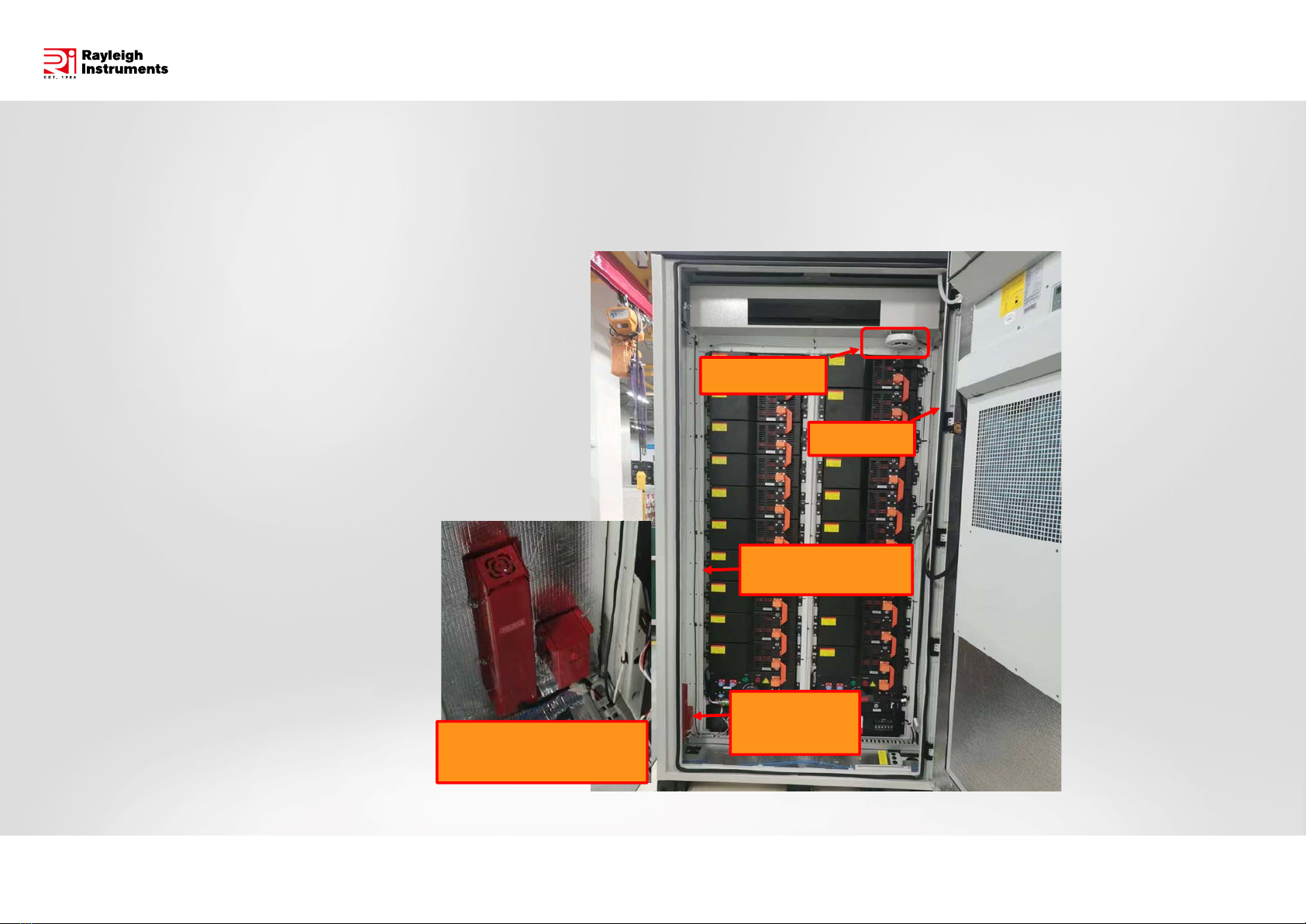
RI-ENERGYSET-3P-ESS-50-100 - Protection Systems
www.rayleigh.com
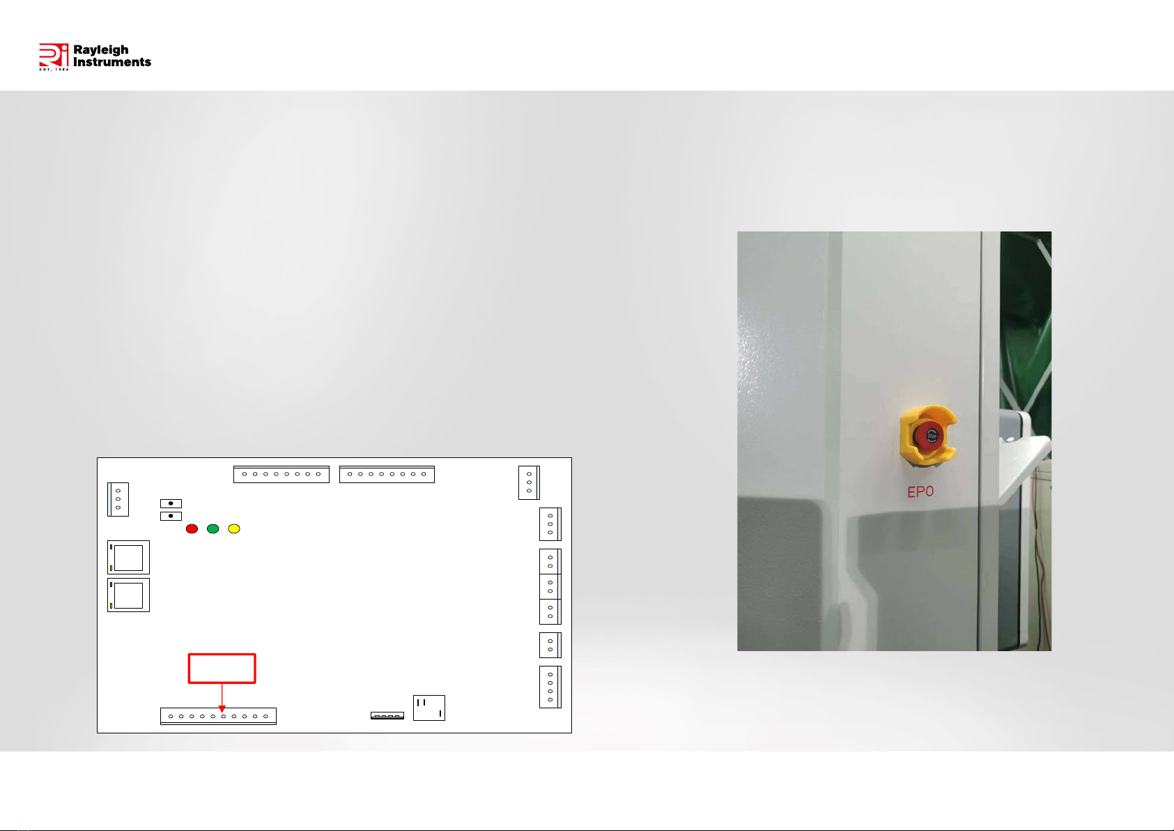
Power
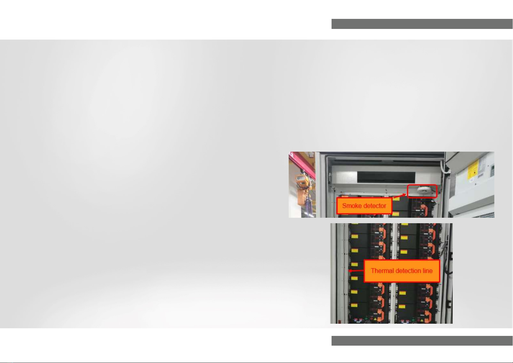
indication LED
Fire Indication
LED(RED)
Circuit detection
indicator LED
Circuit detection
button
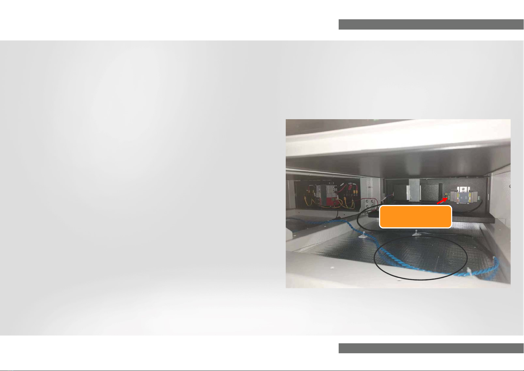
Fire extinguisher
cylinder terminal
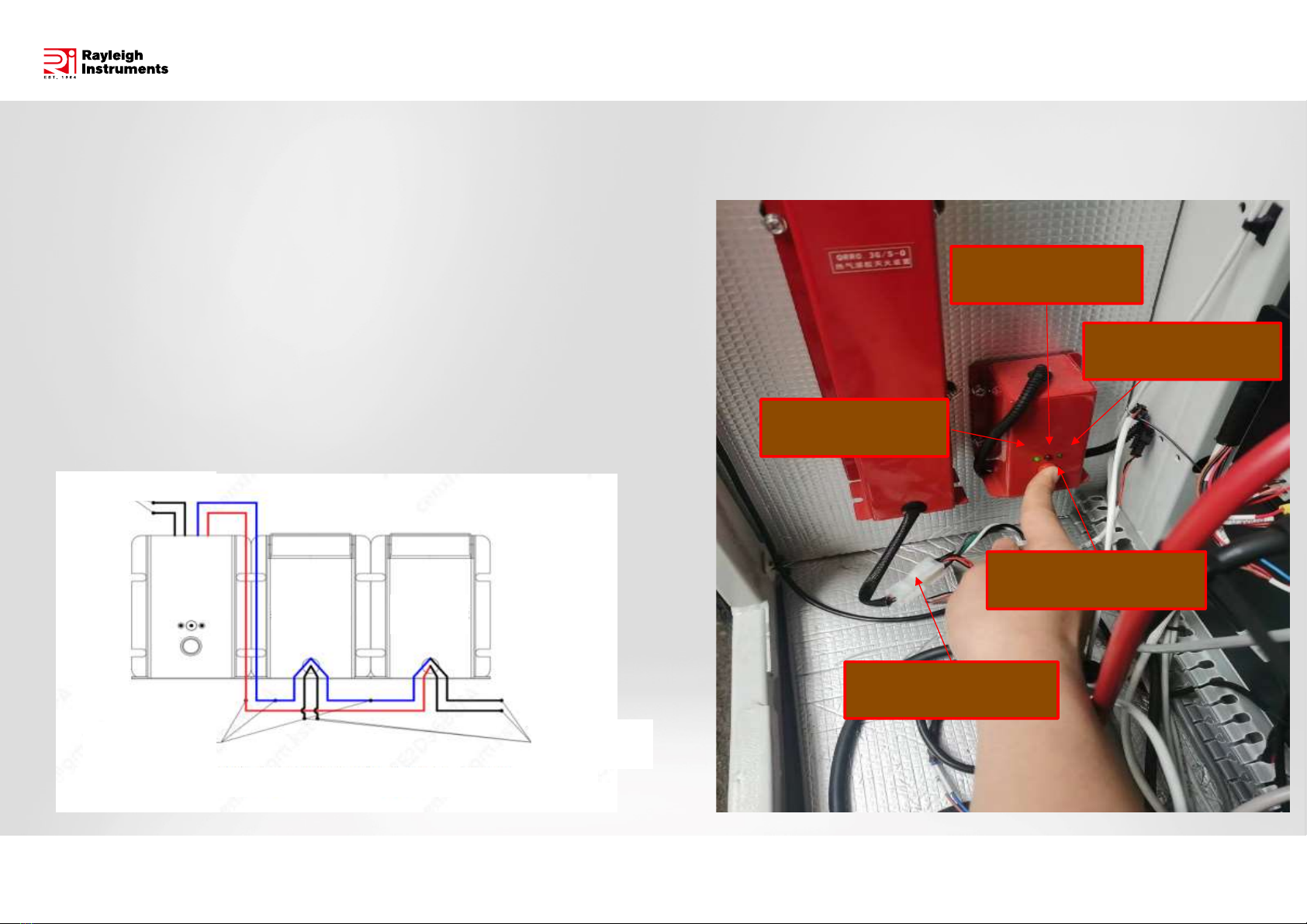
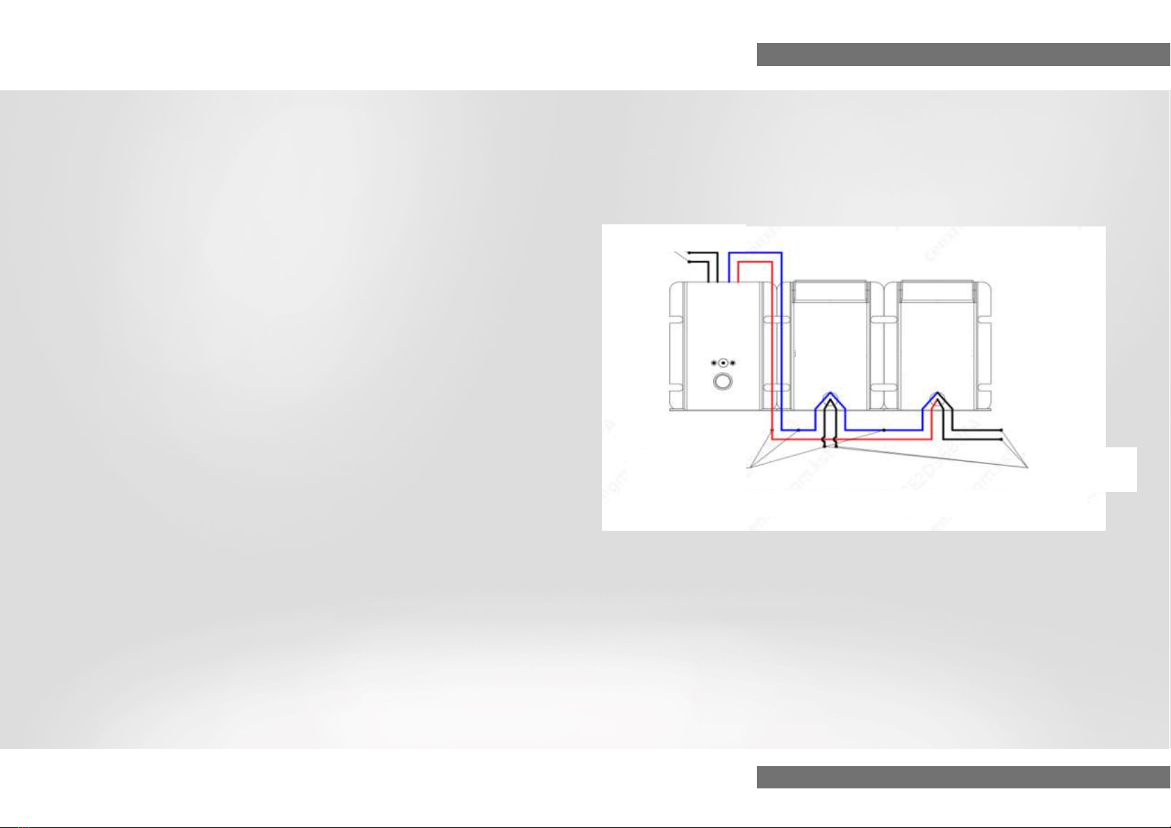
Schematic diagram of the starter box and fire suppression device
Detection(Black)
JR10-Q
Starter
box Hot aerosols
fire suppression
device
Hot aerosols
fire suppression
device
Start signal
(Red and blue)
Feedback
signal (black)
1) During installation & commissioning, or regular inspections, please
ensure that the starter box has sufficient power.
2) During inspections, press the test button to check the battery indicator
lights and circuit detection.
3) It is strictly prohibited to connect the fire extinguisher cylinder terminals
while the fire start indicator light is on.
Cabinet level
Fire Protection Specification
Schematic diagram of the starter box and fire suppression device
Detection(Black)
JR10-Q
Starter
box Hot aerosols
fire suppression
device
Hot aerosols
fire suppression
device
Start signal
(Red and blue)
Feedback
signal (black)
1) JR10-Q Power detection
Pressing the test button, if the battery indicator light on the left side of
the control panel is on, it indicates that the battery pack has sufficient
power. If not, please check the battery connection or contact the
manufacturer for battery replacement.
The effective working time of the power supply is 6 years.
2) JR10-Q Circuit detection
Pressing the test button, if the circuit detection indicator light on the
right side of the control panel is on, it indicates that the fire
suppression system is properly connected. If not, should check for
any disconnections in the wiring between the starter box and the fire
suppression system.
3) JR10-Q Starter indication
When the JR10-Q starter box receives a passive DI, it initiates the
startup process, and the red startup indicator light in the middle of the
starter box panel will be on.
Cabinet level
Fire Protection Specification