BERNINI DESIGN Be172 User manual

1
Be172 Diesel Engine Protection Module Installation Manual 04-April-2022
BE172 Specifications
DC Supply, Battery Plant
5V up to 36 Vdc
Static Outputs (short circuit proof)
200 mA dc
Key Switch Rating
30 A (15 secs)
Dimensions / Cut-out
72X72X55 mm / 68x68mm
Case/Weight
Steel powder-coated / 390 gr
Operating Temperature /H.R.
-30° C /+70° C / 95 n.c.
Mounting
Two clips
DESCRIPTION
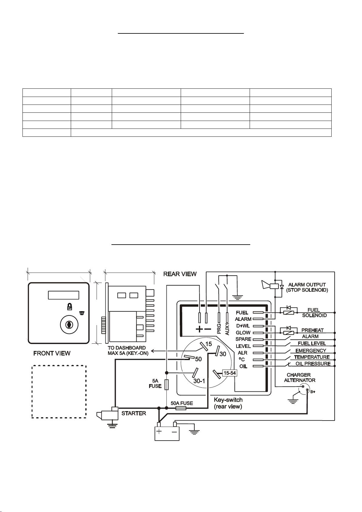
The Be172 includes the basic safeguards to protect a diesel engine. It features a 4-digit military-
grade 7-segment display, 3 static outputs, 7 digital inputs, and a 30Adc-rated key switch. The Be172
monitors an Oil pressure switch, a temperature switch, a fuel level switch, charger alternator voltage and
and auxiliary alarms. The Be172 provides a MANUAL mode of operation via a key-switch. Finally, the
Be172 offers 4 adjustable settings about pre-glow, fuel solenoid, fuel alarm and auxiliary alarm. The
Be172 is an up-grade of the most popular Be72 engine protection module.
WARNING!! High voltage may be present inside the Be172 box. To avoid electric-shock hazards,
operating personnel must not remove the protective cover or door of the panel. Do not disconnect the
grounding connection. The Be172 can start the engine at any time. Do not work on equipment which is
controlled by the Be172. When servicing the engine, disconnect the battery and battery charger. We
recommend that you place warning signs on the equipment indicating the above.
!! W A R N I N G !! Relays and solenoids used together with Be172 must be connected
to flywheel diodes or noise-suppression devices as indicated in the wiring diagram.
1.0 MANUAL START & STOP
A) - When the KEY is in position ‘OFF’, a red dot blinks on the right side of the display. This indicates the
standby mode. All the time you turn the KEY to ‘OFF’ the display indicates the [HOUR COUNT] for about
10 seconds (for example [h 278]). Then, the display turns off. The ‘OFF’ mode clears warnings and
shutdown alarms.
B) - Turn the KEY to ‘ON’. The display indicates the battery voltage for about 5 seconds (for example [b
12.6]).
C) - When the display indicates the prompt [StA-] (it stands for START) you are required to turn the KEY
to ignition in the same way you start a car. When the engine is running, the display indicates a clockwise
rotating animation. In case you programmed a pre-glow the message [ПППП] will immediately appear as
you turn the key on. Then, after the programmed pre-glow time, the prompt [StA-] will take place.
If you forget to start the engine, or the engine fails to start, the Be172 shuts down the fuel after 15
seconds. The display will indicate the message [FAIL] (it stands for starting failure alarm shutdown).
Note1 In normal conditions, when the engine is not running, the Be172 expects the oil pressure switch
closed and no voltage on D+ terminals. If the Be172 finds a different logic condition, it will warn you by
indicating for a few seconds the messages [oil.] or [cHAr.] or both in sequence. You can anyway start the
engine without problems. The Be172 triggers the (ALARM) output reminding you to investigate the issue.
It could be an open connection problem.
D) - Turn the KEY to ‘OFF to stop the engine. The display will indicate for 10 seconds the [HOUR
COUNT]. Then, it will shut down the display. A dot on the right side will blink slowly indicating a standby
status.
Bernini Design srl
ITALY
The information in this document is
subject to change without notice.
bernini@bernini-design.com
support
+39 335 70 77 148

2
2.0 ALARMS LIST
[DISPLAY]
ALARM DESCRIPTION
NOTES
[bELt]
Engine Belt break or Charger failure shutdown. The Be172 triggers this
alarm and shuts down the engine if the input (D+/W.L) is continuously
below 3Vdc for at least 20 seconds.
Check for the belt
or the charger
alternator.
[°C]
Engine High-Temperature alarm. The Be172 triggers this alarm and
shuts down the engine if the switch input (°C) is closed for at least one
second.
Check the engine
cooling system.
[ALAr]
Emergency alarm. The Be172 triggers this alarm and shuts down the
engine if the switch input (ALR) is closed for at least one second.
Check the
emergency
button status.
[FuEL]
Fuel level alarm. The Be172 triggers this alarm if the switch input (FUEL)
is closed for at least one second. Based on the settings of the parameter
[P3], the BE172 triggers a warning (it features auto-reset) or shuts down
the engine after a programmable time.
Refuel the tank
[ALr1]
Alarm 1. The Be172 triggers this alarm if the switch input (ALARM1) is
closed for at least one second. Based on the settings of the parameter
(P4), the BE172 triggers a warning (it features auto-reset) or shuts down
the engine after a programmable time.
Check the Alarm
1 source.
[oiLP]
Low oil pressure. The Be172 triggers this alarm and shuts down the
engine if the oil pressure switch connected to the (OIL) input is closed for
at least one second. This alarm is ignored for 15 seconds after starting
the engine.
Check the oil
level.
[FAIL]
Fail to start alarm. The Be172 triggers this alarm and shuts down the
(FUEL) output if it does not detect, within 20 seconds, a valid source of
engine running from terminal (D+/WL) or a valid transition of the (OIL)
input (closed-to-open).
Check the engine
or check if have
forgotten the KEY
in the ON
position.
[Err-]
The Be172 fails to enter the ‘PROGRAM MODE’ due to an erroneous
inputs setup.
Check the
programming
instructions.
[Err1]
Failure of the memory. Check the supply and retry programming. If the error persists,
replace the Be172.
[Err2]
The supply is lower than 10V. The Be172 denies access to the memory.
Check the dc supply.
[EE.Er]
The Be172 failed the memory initialization routine during the power on. Remove the supply
for a few seconds. If the error persists, replace the Be172.
3.0 FUEL SOLENOID & STOP SOLENOID
In order to stop the engine, we recommend that you use a FUEL SOLENOID (energized to run). This
solenoid must be connected to the output (FUEL) via a pilot relay. If for a particular application, you use
a STOP SOLENOID (energized to stop), you are required to set up the adjustable parameter [P2] as
indicated in the programming instructions. Connect the STOP SOLENOID to output (ALARM) via a pilot
relay as indicated in the wiring diagram. The Be172 will energize the output for the programmed time.
When you use the output (ALARM) to drive a STOP SOLENOID, the ALARM function output will no be
longer available. In other words, the STOP SOLENOID output shares the same output used for ALARM.
Factory setting for the (ALARM) output is ALARM MODE

3
4.0 PROGRAMMING INSTRUCTIONS
The are four adjustable parameters: [P1], [P2], [P3], and [P4]. Follow the instructions.
1) Make sure the battery supply is over 10Vdc; 12Vdc is the optimal supply.
2) Remove the DC supply, turn the key to OFF and connect to the battery minus the terminal (PRG).
3) Connect to the battery minus the TERMINAL associated with the parameter you want to program. The
following table shows the combinations.
DISPLAY
TERMINAL
DESCRIPTION
DEFAULT
OPTIONS
[P1]
(AUX1)
Pre-glow settings
OFF=No preglow
6” 15” 30” 45” 1’
[P2]
(ALR)
Alarm/Stop solenoid
OFF=Alarm mode
5” 15” 30” 45” 1’ 2’
[P3]
(FUEL)
Fuel alarm modes
OFF=Warning only
5’ 10’ 20’ 30’ 60’
[P4]
(SPARE)
Alarm 1 modes
OFF=Warning only
5” 15” 30” 45” 1’ 5’
[Err-]
The Be172 detected a not-valit combination of inputs. For example (PRG) + (OIL) or (PRG) + [°C]
4) Connect the supply. The display will indicate the message [Prog], and for a second, the name of the
parameter ([P1] for example). Finally, the display indicates the active setting (usually the factory default).
5) Turn the key ON. The Be172 will automatically display, in sequence, each available option for two
seconds (if you have selected [P1], the Be\172 display OFF-6”-15”-30”-45”-1’).
6) When you see on display the desired option, immediately turn the key to OFF. The display will blink
twice in order to confirm your option: the Be172 stores and activates the new setting.
7) Remove the supply, remove the (PRG) connection, and remove the (TERMINAL).
8) Apply the supply. After the indication of the internal firmware (four digits code), the Be172 displays the
parameter you modified ([P1] for example) and the setting ([6”] for example). In this way, all the time you
supply the controller. you will be aware of the status of the parameters. If you modify all parameters, the
display will indicate all active settings in sequence.
5.0 RECOMMENDED WIRING DIAGRAM
Relays and solenoids used together with Be172 must be connected to flywheel diodes.
12V / 24V
Recommended
cut - out
68x68mm
Be72 Engine protection
72mm
72mm
50mm
Popular Protection Device manuals by other brands

Aqua Computer
Aqua Computer LEAKSHIELD User and installation manual

Geobrugg
Geobrugg GBE-3000A product manual

Arcteq
Arcteq AQ-G3 7 Series instruction manual

HOZAN
HOZAN F-66-S instruction manual

Kemo Electronic
Kemo Electronic M148-24 instructions

OBO Bettermann
OBO Bettermann PDP-2-5-D Mounting instructions