Allen Sports XLT2 User manual
INSTRUCTIONAL OWNER’S MANUAL
PRODUCT REGISTRATION:
MAKE SURE TO REGISTER YOUR PURCHASE AT
http://allensportsusa.com/about/product-registration
TO QUALIFY FOR PRODUCT WARRANTY AND TO RECEIVE
IMPORTANT PRODUCT NOTIFICATIONS 1
MODEL XLT2 BIKE TRAILER
Owner’s Manual should be kept for future reference
WARNING
WARNING
WARNING
WARNING
1. Completely read and understand Owner’s Manual before assembling or operating this product.
2. This product should be assembled by an adult
IMPORTANT SAFETY INFORMATION
• Failure to follow these warnings and assembly instructions could result in serious injury or death!
• Immediately discard all plastic bags and plastic wrapping materials!
• Maximum weight capacity for this trailer is two (2) children at 100 pounds, max payload!
• Never use this trailer/stroller if it becomes damaged!
• To avoid serious injury, children should always wear the seat belt and the shoulder straps!
• Do not install a car seat or any other seating device not approved by the manufacturer inside the trailer!
• A reflector that complies with CPSC regulations must be visible on the rear of trailer.
• Never leave children unattended in or around this product!
• Never allow children to assemble, fold, or disassemble this unit!
• Accessories or parcels placed in trailer/stroller may cause it to become unstable!
• Not for use with children under 12 months old! Children must be able to support their own heads!
• Before riding, check that all parts are assembled according to the manufacturer instructions!
Also, ensure that the trailer does not interfere with braking, pedaling, or steering of the bicycle!
• Do not allow any of the child’s body, clothing, shoe laces, or toys to come into contact with moving parts!
• Make no modifications to the trailer!
• Tires should be inflated to 25-35 PSI for maximum comfort! Check tire pressure before each use!
• Use a foot pump or hand pump to inflate tires! Pressurized air hoses can cause over inflation!
• Periodically re-check all fasteners to make sure they are tight!
• Clean trailer only with soap and water. Do not use solvents!
TOWING TIPS:
• Make sure your bike brakes work properly! Braking distance is increased when pulling a trailer!
• This trailer is wide! Allow extra clearance near curbs, signs, parked cars, and other obstacles!
• A bicycle with trailer attached requires a wide turning radius! Do not turn sharply!
• Children must wear an approved safety helmet when using this product in trailer mode!
• Never remove protective canopy when pulling children in the trailer!
• Always use the safety flag when pulling this trailer!
• Do not ride over curbs! Avoid bumps and holes! Always signal your turns!
• Use extra caution when turning on uneven pavement, and going downhill!
• Not for use at high speeds! Do not exceed 10 MPH!
• NEVER use this trailer at night!
• Install a rearview mirror on your bike to check on children in trailer!
• Dress children appropriately to prevent them from getting chilled or overheated while riding!
Protect against wind-chill in cold temperatures, and provide adequate ventilation and hydration
during warmer temperatures.
SAFETY TOWING TIPS

INSTRUCTIONAL
OWNER’S MANUAL2
FULLY ASSEMBLED TRAILER
QUANTITY DESCRIPTION
1 Frame w/ Canopy, Sling
Seat with 5 point safety
harness, tow bar, tow
bar coupler and rear
wheel bracket attached
2 20” Rear wheels
1 Safety flag
PARTS LIST

INSTRUCTIONAL
OWNER’S MANUAL3
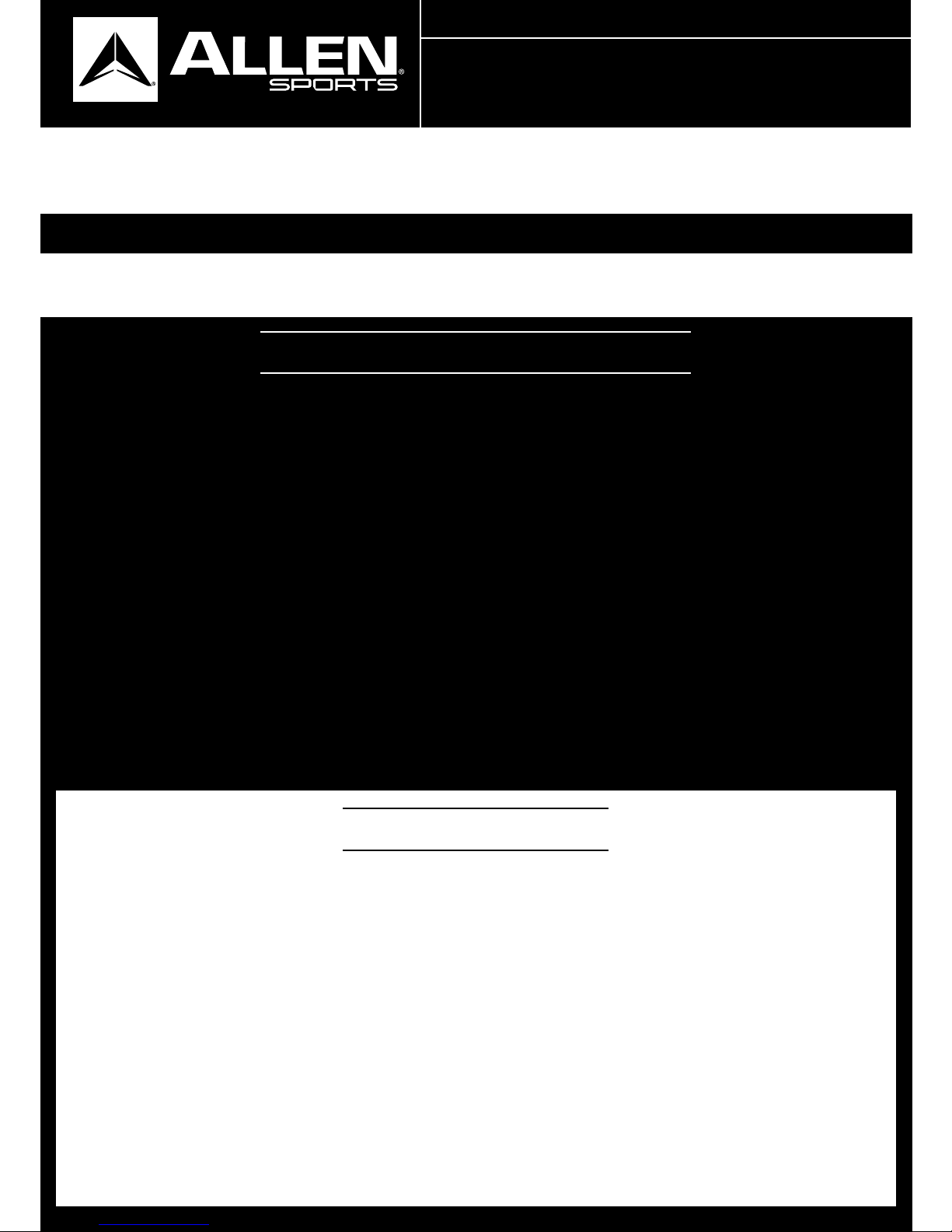
TRAILER ASSEMBLY & OPERATING INSTRUCTIONS
STEP 1:
STEP 2:
WARNING!: IMMEDIATELY DISCARD ALL PLASTIC BAGS AND WHEEL
WRAPPING MATERIALS!
WARNING!: You must make certain the frame is locked before using the trailer. Failure to do so could result in
serious injury to you or your child.
Remove the trailer, wheels, hitch arm and walking kit from the box.
OPEN FRAME
A. Remove trailer and all components from carton. Unfold trailer by pulling the frame and remove all
components from inside (Fig. 2a).
B. Lift both side panels into an upright position (Fig 2b). Lift the crossbar with seatback attached, and
slide the connector located on the crossbar into the slot in the locking mechanism on the window panel
as show (Fig 2b). Make sure both sides are locked in place. When locking, you will hear an audible “click”
to indicate the mechanism is engaged. After assembly, attempt to pull the crossbar out by tugging on the
bar – it should not come out
C.To remove the crossbar for folding, press the red release button while pulling the crossbar up and away
from the frame (Fig 2c).
FIGURE 2a FIGURE 2b.
FIGURE 1
FIGURE 2c
Your xlt2 trailer uses simple and convenient push button quick-release wheels.
STEP 1:
STEP 2:
STEP 3:
STEP 4:
Push the button on the outside of the wheel hub.
Insert the axle through the hanger bracket on the frame as shown (fig 3).
Push all the way in and release the pushbutton. The wheel is automatically
locked in place.
Give each wheel a tug to make sure they are secure.
WHEEL INSTALLATION
FIGURE 3
NOTE: 1. Set the jogger kid aside, as you will install this later.
2. Lay the trailer on the ground with the black fabric
side down.
INSTRUCTIONAL
OWNER’S MANUAL4
TOW ARM
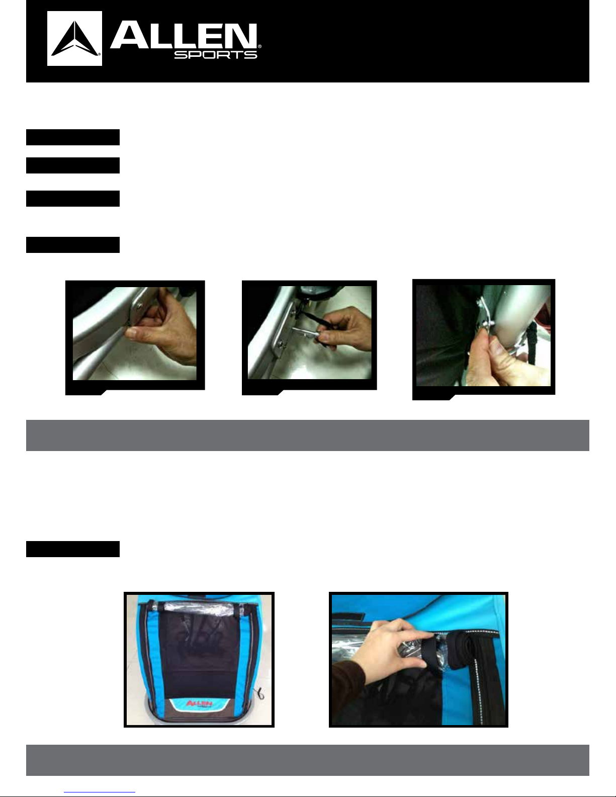
TOP COVER/WINDSCREEN
WARNING!: Check this pin periodically during and before each use to be sure it has not become loose.
Failure to do so could result in serious injury to you or your child.
WARNING!: Rocks and castoff from the bicycle wheels could injure your child. Never use the trailer without closing the
mesh cover. Failure to do so could result in serious injury .
STEP 1:
STEP 2:
STEP 3:
STEP 4:
Depress the spring pin and insert the hitch arm in the bracket on the frame as shown (fig 4b).
Once the spring pin locks in place in the hole in the bracket, Locate the quick release pin,
located on the trailer frame, then Insert the pin through the bracket and into the hole in
the tow arm. The pin should go completely through the tow arm and bracket. (fig 4c)
Give the pin a tug to be sure it is secure.
NOTE: The clear vinyl windscreen and the protective mesh barrier zip open for loading. In inclement weather, the clear
windscreen protects your passengers from the elements. Weather permitting, you can roll up the clear window
and affix with Velcro straps provided. The mesh allows ventilation, but prevents debris from entering the trailer.
FIGURE 4a FIGURE 4b FIGURE 4c
Locate the hitch arm, and position on the left side of the trailer, as shown (fig 4a).
The hitch arm is held in place by a spring pin and a quick release pin.
INSTRUCTIONAL
OWNER’S MANUAL5
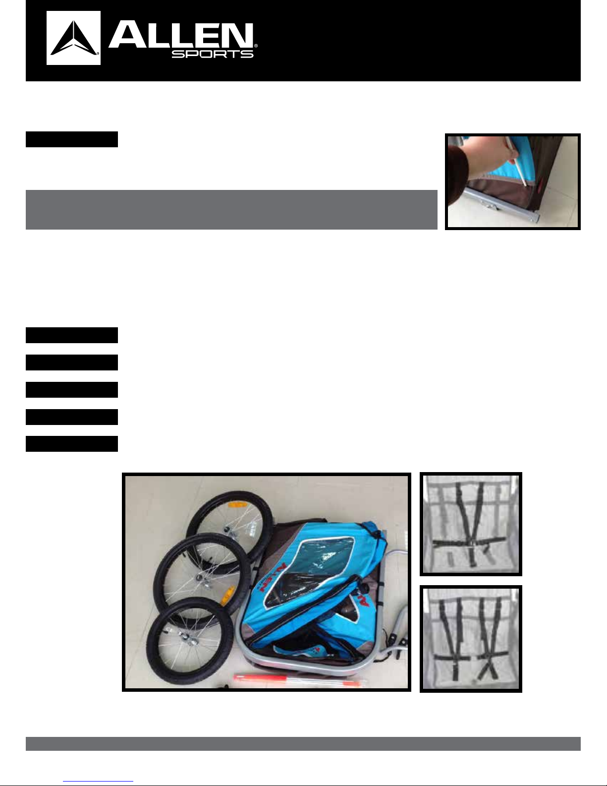
SAFETY FLAG INSTALLATION
STEP 1: Assemble the flag and insert the end into the small sleeve on the side of the
trailer skin.
WARNING!: This flag is meant for use only with the trailer. This flag is not a toy. Do not let
your child play with this flag at any time. Failure to comply with this warning
could result in serious injury of your child.
HARNESS
STEP 2:
STEP 3:
STEP 4:
STEP 5:
STEP 1:
Unclip the straps and place your child in the seat. Adjust the upper buckles to fit snugly
above your child’s shoulders.
Place a single child in the center and use the center strap in the middle. For two children use
the outer center straps and shoulder straps
The crotch strap buckle should come just below your child’s belly button, where a normal belt
could lay. Adjust the ladder lock so the buckle is in the correct position
Buckle the two side straps to the crotch strap and adjust snugly so you can fit average size
fingers between belt and your child.
The buckle should be centered in your child’s abdomen. Hook the shoulder straps to the
D-rings on the buckle and adjust the ladder locks so they fit snugly.
WARNING!: To avoid serious injury or death, children should always wear the seat belt and shoulder straps and helmet.
FIGURE 15.
INSTRUCTIONAL
OWNER’S MANUAL6
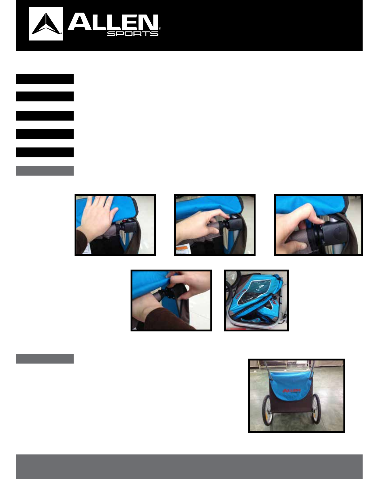
FOLDING
STORAGE
STEP 1:
STEP 3:
STEP 2:
STEP 4:
STEP 5:
To fold your trailer, first, release safety harnesses and allow passengers to exit the trailer
Open the rear compartment flap and locate the release latches on the side frame tubes.
Make sure to remove any items stored inside the trailer or in the cargo area behind the seat.
To operate the latches, first depress the locking button, and then lift to release the crossbar.
Push crossbar down and away, allowing the two side panels to fold down.
NOTE: The trailer can be folded with or without the wheels on. If the wheels are removed, they can be
stowed inside the trailer when not in use. To remove the wheels, simply push the button in the
wheel, and pull the wheel out from the frame.
NOTE: The trailer has a rear storage area located behind the seat.
This is not intended for items weighing more than 10 lbs. It can
be accessed by opening the rear logo flap.
WARNING!: Distribute items carefully and evenly. Items may cause the trailer to become unstable. Failure to comply
with this warning could result in serious injury to your child..
INSTRUCTIONAL
OWNER’S MANUAL7
FIGURE 5a FIGURE 5b FIGURE 5c
HITCH
Attaching trailer to bicycle
Removal of trailer
NOTE: This trailer is not designed to be used with electric bikes or motorcycles, or any motorcycle or any
motorized vehicle.
STEP 1:
STEP 1:
STEP 3:
STEP 3:
STEP 2:
STEP 2:
STEP 4:
STEP 4:
Loosen left side rear axle to allow the hitch to attach to frame.
Remove Safety strap by releasing D-ring
Tighten axle nut securely, testing to see the hitch is unable to pull loose (Fig 5b).
Pull trailer arm away from black hitch
Position hitch over left rear axle of bicycle frame (Fig5a).
Remove QR snap pin from hitch connection
Loop Safety Strap around frame and secure to D-ring on hitch arm (Fig 5c).
Black Hitch attached to axle can remain with the bicycle for easy reattachment.
WARNING!: Safety strap must attach to the bike frame when using this product in trailer mode. QR snap pin must be in
place and locked before riding. Added weight of it’s passengers or cargo, or both will affect the handling
characteristics of the bicycle to which it is attached.
Your iGO trailer is designed to attach easily to just about any full-size bicycle. The hitch fitting must be attached to
the rear axle of the bike. Do not attach to any cycle where it cannot attach to the axle. It is recommended that the
bicycle(s) to which the trailer will be attached undergo a safety check by a qualified bicycle mechanic before
attaching the trailer to it.

INSTRUCTIONAL
OWNER’S MANUAL8
TRAILER MAINTENANCE
PARKING BREAK
STEP 1:
STEP 1:
STEP 3:
STEP 2:
STEP 2:
Before each ride:
a. Check all fasteners to make sure they are tight. Tighten or replace if needed
b. Check to make sure wheels are fully secure in the frame. Wheels must be fully
inserted to lock in place, Attempt to pull the wheel out without pushing the release button.
Wheel should not move.
c. Check tires for wear and proper inflation as listed on tire sidewall. Use only hand
operated pump to avoid tire damage. Underinflation or overinflation can result in unsafe
handling.
d. Double check hitch attachment, making sure QR pin is locked, and safety strap is
in place.
e. Check harness straps for wear, and make sure buckles lock properly
As needed
a. Trailer can be clean with mild detergent and water. Do not remove the seat or cover for
washing. Do not use harsh chemicals or cleaners, as they may damage the fabrics or the
frame materials or surfaces.
Figure 6b shows the parking brake in locked position, appropriate for parking or when loading the trailer.
Annual check-up
a. Once a year, or sooner if needed, have the trailer inspected by a qualified bicycle mechanic
for signs of wear or needed adjustment.
Figure 6a shows the brake mechanism on the trailer in normal unlocked position. In this case, the
locking lever faces forward , parallel to frame. The brake housing also acts as a wheel guard to
protect the wheel from direct contact with objects that might stop the wheel.
NOTE: When releasing the brakes, make sure to return the lever to the position parallel to the frame,
to fully release the brake.
FIGURE 6a FIGURE 6b
Your trailer will give you many years of service with minimal care.
To ensure safe and dependable operation, we recommend the following regular maintenance:
Your trailer is equipped with combination wheel guard/parking brakes for added safety.
When loading or unloading or parking your trailer, engage the parking brakes to prevent the trailer from moving.

INSTRUCTIONAL
OWNER’S MANUAL9
IF YOUR PRODUCT REQUIRES WARRANTY SERVICE, PLEASE DO NOT RETURN IT TO RETAIL STORE.
PLEASE CONTACT:
ALLEN SPORTS USA
Please note that all returns and exchanges are subject to the return policy of the retailer where
the product was originally purchased
R. A. ALLEN CO., INC. 60 THOREAU ST. 161 CONCORD, MA 01742
Product designed in USA, Made in Ningbo, China
WARRANTY
@AllenSportsUSA@AllenSportsUSA/AllenSportsUSA
Get the lastest news, info, give-a-ways
and pics on our social media sites!

INSTRUCTIONAL
OWNER’S MANUAL10
MODEL XLT2 JOGGER KIT
Owner’s Manual should be kept for future reference
WARNING
WARNING
WARNING
WARNING
1. Completely read and understand Owner’s Manual before assembling or operating this product.
2. This product should be assembled by an adult
IMPORTANT SAFETY INFORMATION
WARNING #1:
• Failure to follow these warnings and assembly instructions could result in serious injury or death!
• Immediately discard all plastic bags and plastic wrapping materials!
• Maximum weight capacity for this trailer is two (2) children at 100 pounds, max payload!
• Never use this trailer/stroller if it becomes damaged!
• To avoid serious injury, children should always wear the seat belt and the shoulder straps!
• Do not install a car seat or any other seating device not approved by the manufacturer inside the trailer!
• A reflector that complies with CPSC regulations must be visible on the rear of trailer.
• Never leave children unattended in or around this product!
• Never allow children to assemble, fold, or disassemble this unit!
• Accessories or parcels placed in trailer/stroller may cause it to become unstable!
• Not for use with children under 12 months old! Children must be able to support their own heads!
• Before riding, check that all parts are assembled according to the manufacturer instructions!
Also, ensure that the trailer does not interfere with braking, pedaling, or steering of the bicycle!
• Do not allow any of the child’s body, clothing, shoe laces, or toys to come into contact with moving parts!
• Make no modifications to the trailer!
• Tires should be inflated to 25-35 PSI for maximum comfort! Check tire pressure before each use!
• Use a foot pump or hand pump to inflate tires! Pressurized air hoses can cause over inflation!
• Periodically re-check all fasteners to make sure they are tight!
• Clean trailer only with soap and water. Do not use solvents!
TOWING TIPS:
• Make sure your bike brakes work properly! Braking distance is increased when pulling a trailer!
• This trailer is wide! Allow extra clearance near curbs, signs, parked cars, and other obstacles!
• A bicycle with trailer attached requires a wide turning radius! Do not turn sharply!
• Children must wear an approved safety helmet when using this product in trailer mode!
• Never remove protective canopy when pulling children in the trailer!
• Always use the safety flag when pulling this trailer!
• Do not ride over curbs! Avoid bumps and holes! Always signal your turns!
• Use extra caution when turning on uneven pavement, and going downhill!
• Not for use at high speeds! Do not exceed 10 MPH!
• NEVER use this trailer at night!
• Install a rearview mirror on your bike to check on children in trailer!
• Dress children appropriately to prevent them from getting chilled or overheated while riding!
Protect against wind-chill in cold temperatures, and provide adequate ventilation and hydration
during warmer temperatures.
SAFETY TOWING TIPS
INSTRUCTIONAL
OWNER’S MANUAL11
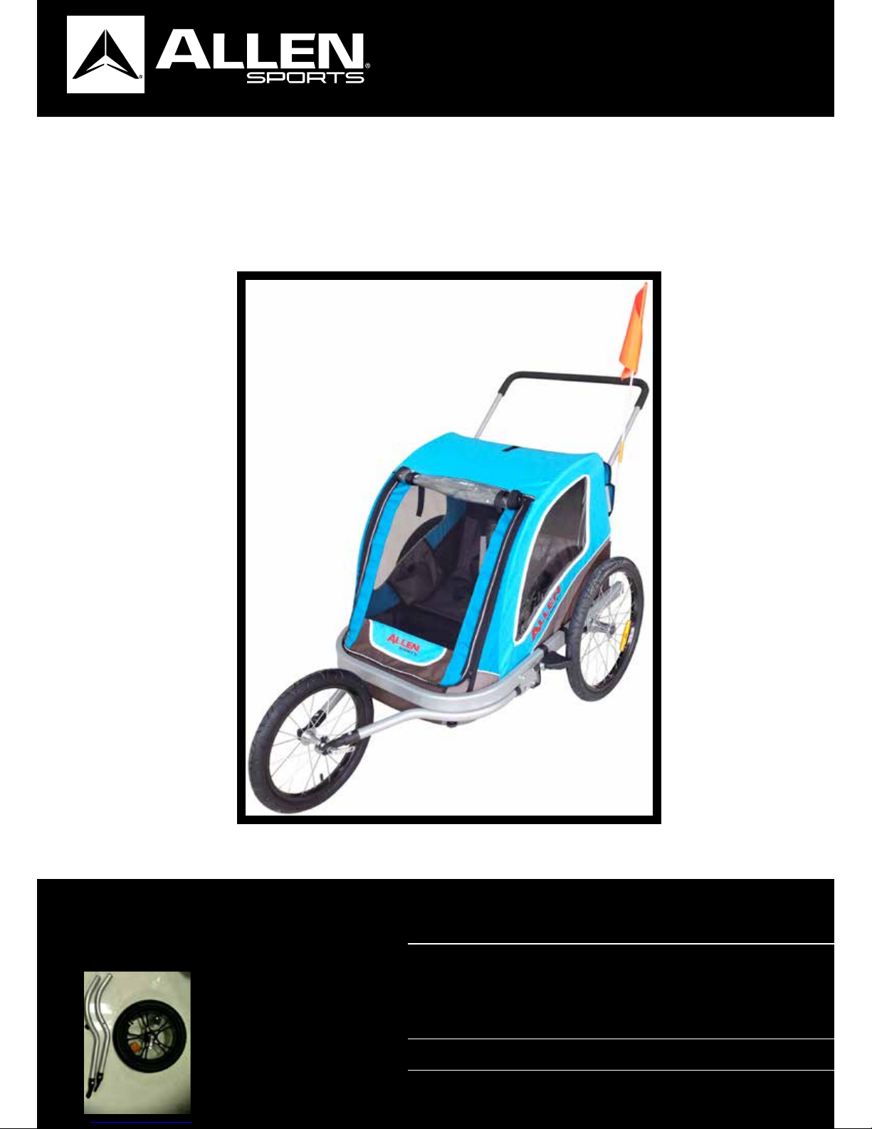
FULLY ASSEMBLED TRAILER + JOGGER
QUANTITY DESCRIPTION
1 quick release 16 inch wheel,
handlebar,
mounting hardware
2 fork tubes
1 safety wrist strap
Your XLT2 trailer can accept
an optional jogger kit. If not
included with your trailer at
time of purchase, please
contact your retailer for
more information on how
to purchase this accessory.
PARTS LIST

INSTRUCTIONAL
OWNER’S MANUAL12
JOGGER ASSEMBLY
STEP 1:
STEP 2:
STEP 3:
To install the jogger kit, first remove the hitch arm by releasing opening and releasing the QR pin,
then press the spring pin and pull out the arm. Also remove the pin on the opposite side clamp.
Next, take one arm, ( Right and left arms are not the same, note the screw thread faces up),
insert into the aluminum bracket, align with the fixing hole and insert and lock the spring pin.
Tighten the fixing screw into the threaded nut in the bottom of the front frame tube. Perform
same action for both fork tubes.
NOTE: Make sure spring pin is locked. If not locked, the pin may fall out, releasing the fork. This may cause injury
to you or your child.

INSTRUCTIONAL
OWNER’S MANUAL13
STEP 1:
STEP 2:
STEP 1:
STEP 2:
Open the quick release axle skewer to allow the axle to fit inside the plastic fork tips. Align the
flats on the axle with the flats on the fork tips, and slide into the slots.T
Close the QR lever, making sure it is tight. If the wheel Is still loose in the frame, open the re-
lease lever, tighten the thumb nut, and close the lever again. Repeat this until there is sufficient
resistance to securely lock the wheel.
Take the small tubes with hardware, and using bolts and nuts
provided, assemble to the holes in the rear of the frame.
Using the spanner and hex wrench included, tighten securely
as shown.
insert handlebar in the small tubes you have just installed on the frame. Depress the spring pins
and allow the handlebar to slide in to the small tubes until they lock in place.
NOTE: Make sure the long portion of the handlebar fixing tube is up,
as shown.
NOTE: When using the trailer as a jogger, make sure to use the safety wrist strap shown above.
INSTALL WHEEL
INSTALL HANDLEBAR
NOTE: If the wheel does not track straight, loosen the lever and shift the wheel in the slot to adjust the direction,
and retighten.

INSTRUCTIONAL
OWNER’S MANUAL14
IF YOUR PRODUCT REQUIRES WARRANTY SERVICE, PLEASE DO NOT RETURN IT TO RETAIL STORE.
PLEASE CONTACT:
ALLEN SPORTS USA
Please note that all returns and exchanges are subject to the return policy of the retailer where
the product was originally purchased
R. A. ALLEN CO., INC. 60 THOREAU ST. 161 CONCORD, MA 01742
Product designed in USA, Made in Ningbo, China
WARRANTY
@AllenSportsUSA@AllenSportsUSA/AllenSportsUSA
Get the lastest news, info, give-a-ways
and pics on our social media sites!
Table of contents
Other Allen Sports Bicycle manuals


