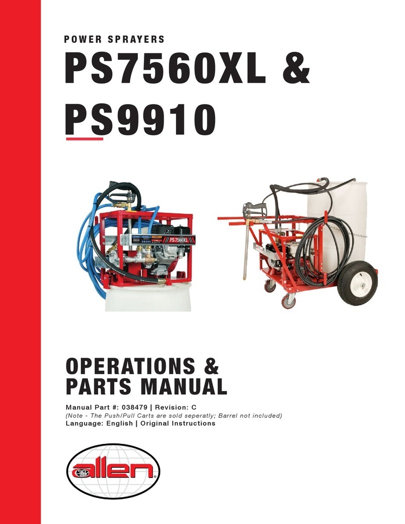
allen 6500 User manual

Power S
Power Sprayers
prayers
OPERATIONS
PARTS
MANUAL
BOOK
MM
MMOO
OODD
DDEE
EELL
LL
6500
6500
7560
7560
7560XL
7560XL
9910 w/ 5.5 Kawasaki
9910 w/ 5.5 Honda
9910 w/ 5.5 Honda
THIS MANUAL COVERS HIGH PRESSURE SPRAYERS(S) BELOW
PRINTED 4/01
II
IITT
TTEE
EEMM
MM
NN
NNOO
OO..
..
# 029421
# 029421
# 029414
# 029414
# 029424
# 029424
# 039069
# 039069
# 039069
# 039069

LIMITED W
LIMITED WARRANTY
ARRANTY
Allen Engineering Corporation warrants its products to be free of defects in material or workmanship for the fol-
lowing periods:
A. All New Machines and Part 6 Months
B. All New Gear Boxes 2 Years
C. All Factory Reconditioned Gear Boxes 1 Year
Warranty period begins on first day of use by End User. This first day of use is established by a completed war-
ranty card or a Bill of Sale to the end user. All warranty is based on the following limited warranty terms and
conditions.
1. Allen Engineering Corporation’s obligation and liability under this warranty is limited to repairing or replac-
ing parts if, after Allen’s inspection, it is determined to be a defect in material or workmanship. Allen
Engineering Corporation reserves the choice to repair or replace.
2. If Allen Engineering Corporation chooses to replace the part, it will be at no cost to the customer and will
be made available to the Distributor/Dealer from whom the customer purchased the product.
3. Replacement or repair parts, installed in the product, are warranted only for the remainder of warranty peri-
od of the product as though they were the original parts.
4. Allen Engineering Corporation’s warranty applies only to the products that are manufactured by Allen
Engineering and does not cover component parts such as engines and clutches. Allen Engineering
Corporation DOES NOT warranty clutches. Engine warranty claims should be made directly to an author-
ized factory service center for the particular engine make.
5. Allen Engineering Corporation’s warranty does not cover the normal maintenance of products or its compo-
nents (such as engine tune-ups and oil changes). The warranty also does not cover normal wear and tear
items (such as belts and consumables).
6. Allen Engineering Corporation’s warranty will be void if it is determined that the defect resulted from opera-
tor abuse, failure to perform normal maintenance on the product, modification to product, alterations or
repairs made to the product without the written approval of Allen Engineering Corporation. Allen
Engineering Corporation specifically excludes from warranty any damage to any trowels resulting from an
impact to the rotors. Allen Engineering Corporation also excludes from warranty any failure of clutches on
any engine driven piece of equipment.
7. If a new gear box has a factory defect within the first year of use, Allen Engineering Corporation will either
repair the gear box or replace it with a new gear box. If a new gearbox has a factory defect in the second
year of use, Allen Engineering Corporation will either repair it or replace it with a factory reconditioned gear
box. Impact damage is NOT covered under the gear box warranty.
8. Allen engineering Corporation will pay shop labor repair on warranty at the Allen Engineering Shop Labor
Rate in existence on the date of the warranty claim. An Allen Engineering Labor Chart will determine the
time allowed to complete a repair and will govern the shop labor hours that will be allowed.
9. Allen Engineering Corporation will pay freight on warranty replacement parts at Worldwide standard ground
rates. No warranty replacement parts will be shipped air freight at the expense of Allen Engineering
Corporation. Allen Engineering only pays outbound freight charges when sending warranty replacement
parts to the customer VIA ground service. Allen Engineering does not pay any inbound freight, however, if
Allen Engineering determines this to be warranty defect only then will Allen Engineering reimburse the cus-
tomer for inbound freight at standard ground rates.
10. Allen Engineering Corporation’s warranty policy WILL NOT COVER the following; taxes, shop supplies,
environmental surcharges, air freight, travel time, loss of rental revenue, or any other charges whatsoever
or any liabilities for direct, incidental, or consequential damage or delay.
11. Allen Engineering Corporation makes no other warranty, expressed or implied. This limited war-
ranty is in lieu of the warranty of merchantability and fitness. There are no other warranties that
extend beyond the description on this document.
12. No Allen Engineering Corporation employee or representative is authorized to change this warranty in any
way or grant any other warranty unless such change is made in writing and signed by an officer of Allen
Engineering Corporation.

1A
ASSEMBLY
1.1 Assembly of Razorback®Power Sprayers
to a barrel.
After you have uncrated all components received, place
the sprayer (A) on top of the barrel.
Using the barrel locks (B) supplied, fasten the sprayer to
the barrel.
Take the suction tube (C) and the 5’ X 3/4” hose (D) that
is supplied and fasten together. Put the suction tube in
the larger hole of the barrel. Connect opposite end of suc-
tion hose to the 3/4” QDC connector located on the
sprayer.
Take the bypass tube (E) and the 5’ X 1/2” hose (F) that is
supplied and fasten together. Put the bypass tube in the
smaller hole of the barrel. Connect opposite end of the
bypass hose to the 1/2” QDC connector located directly
below the flow control valve.
Locate the spray wand hose (G). This hose will be the
longer of the three. Connect one end to the spray wand
(H) and the opposite end to the1/2” QDC connector locat-
ed on the 90 degree elbow below the flow control valve on
the sprayer.
NOTE: Your sprayer and components may differ from the
one shown in Fig. 1. This will depend on what model you
order.
1.2 Assembly of Razorback®Power Sprayers
to a Push Cart.
After you uncrate all components received, place the
sprayer (A) on the push cart (B). Use the fasteners pro-
vided to fasten the sprayer to the frame. If you are using
a 9910 sprayer, you will need to remove the right hand
side, handle to frame, brace (C) in order to place this
sprayer onto the frame. After the 9910 sprayer is fastened
to the frame, replace the brace. If you are using a 6500,
7560, or a 7560XL sprayer, this brace will not have to be
removed.
Take the suction tube (D) and the 5’ X 3/4” hose (E) that
is supplied and fasten together. Put the suction tube in
the larger hole of the barrel. Connect opposite end of suc-
tion hose to the 3/4” QDC connector located on the
sprayer.
ASSEMBLY INSTRUCTIONS
A
B
DD
E
C
F
F
G
G
H
Fig. 1
Model 9910 Sprayer and Components Shown
Fig. 2
B
A
C
D
E
E
G
F
H
G
H
I
1A-1

1A
ASSEMBLY
Take the bypass tube (F) and the 5’ X 1/2” hose (G) that
is supplied and fasten together. Put the bypass tube in
the smaller hole of the barrel. Connect opposite end of
the bypass hose to the 1/2” QDC connector located
directly below the flow control valve.
Locate the spray wand hose (H). This hose will be the
longer of the three. Connect one end to the spray wand
(I) and the opposite end to the1/2” QDC connector locat-
ed on the 90 degree elbow below the flow control valve
on the sprayer.
NOTE: Your sprayer and components may differ from the
one shown in Fig. 2. This will depend on what model you
order.
1.3 Assembly of Razorback®Power Sprayers
to a Tow Cart.
After you have uncrated all components received,
remove cotter key and washer (A). Slide out the pin in
order to install the tow handle (B).
Next place the sprayer (C) on the tow cart (D). Use the
fasteners provided to fasten the sprayer to the frame. If
you are using a 9910 sprayer, place the sprayer to the
front of the frame away from the barrel. If you are using a
6500, 7560, or a 7560XL sprayer, this process will not
have to be done.
Take the reducer (E) and the 5’ X 3/4” hose (F) that is
supplied and fasten together. Connect that end to the
larger hole on the barrel. Connect opposite end of suction
hose to the 3/4” QDC connector located on the sprayer.
Take the 5’ X 1/2” bypass hose (G) that is supplied and
fasten to the smaller hole on the barrel. Connect oppo-
site end of the bypass hose to the 1/2” QDC connector
located directly below the flow control valve.
Locate the spray wand hose (H). This hose will be the
longer of the three. Connect one end to the spray wand
(I) and the opposite end to the1/2” QDC connector locat-
ed on the 90 degree elbow below the flow control valve
on the sprayer.
NOTE: Your sprayer and components may differ from the
one shown in Fig. 3. This will depend on what model you
order.
ASSEMBLY INSTRUCTIONS Cont’d
Fig. 3
A
B
C
D
G
F
F
E
G
H
I
NOTE: Barrels are not sold by Allen Engineering
Corporation
1A-2
NOTE: WHEN USING THE TOW CART, BE SURE THAT THE
LARGER HOLE OF THE BARREL IS ON BOTTOM. THIS HOLE IS
FOR SUCTION. WHEN INSTALLING THE BYPASS HOSE (G) INTO
THE SMALLER HOLE, LEAVE A LITTLE LOOSE. IF NOT, POKE OR
DRILL A HOLE (J) THE BARREL. THIS WILL HELP AIR FLOW. IT
WILL ALSO PREVENT THE COLLAPSING OF THE BARREL (Refer
to Fig. 3)
J

2A
OPERATIONS
OPERATIONS
SERIAL NUMBER LOCATION
An identification listing the Serial Number is attached to each unit and is located on the base of the mainframe. The num-
ber should not be removed.
Please record the information found so it will be available should the identification become damaged . When ordering parts
or requesting service information you will always be asked to specify the model number and serial number of the unit.
Serial Number
The serial number, found on the barrel lock lug,
is a six digit number. The model number identi-
fies your machine and will ensure that you
receive the correct replacement parts.
123456
Production Sequence
Identification
Plate
Location FILL IN FOR FUTURE REFERENCES
Model Number:___________________
Serial Number:___________________
Date Purchased:__________________
Purchased From:_________________
________________________________
2A-1
Model Number
6500 w/ 25’ Hose
7560 w/ 25’ Hose
7560XL w/ 25’ Hose
9910 w/ 25’ Hose
HOSE LENGTH
(OPTIONAL)
POWER SPRAYER
PUMP SIZE
The serial number is locat-
ed on the barrel lock tab on
the motor end.

2A
OPERATIONS High Pressure Sprayer Operating Information
TABLE OF CONTENTS
1.1 Safety Note . . . . . . . . . . . . . . . . . . . . . . . . . . . . . . . . . . . . . . .2A-5
1.2 Laws Pertaining to Spark Arrestors . . . . . . . . . . . . . . . . . . . .2A-5
1.3 Operating Safety . . . . . . . . . . . . . . . . . . . . . . . . . . . . . . . . . . .2A-6
1.4 Service Safety . . . . . . . . . . . . . . . . . . . . . . . . . . . . . . . . . . . .2A-7
1.5 Dimensions . . . . . . . . . . . . . . . . . . . . . . . . . . . . . . . . . . . . . . .2A-7
1.6 Technical Data . . . . . . . . . . . . . . . . . . . . . . . . . . . . . . . . . . . .2A-8
1.7 Periodic Maintenance . . . . . . . . . . . . . . . . . . . . . . . . . . . . . . .2A-8
1.8 9910 D30 Diaphragm Pump . . . . . . . . . . . . . . . . . . . . . . . . . .2A-9
This machine is built with user safety in mind. However, it can present hazards if
improperly operated and serviced. Follow operating instructions carefully!
If you have any questions about operating or servicing this equipment please contact
your Allen Engineering Distributor or Allen Engineering Corp. Customer Service at
800-643-0095 or 870-236-7751.
2A-2

2A
OPERATIONS
Important Reminder
Complete any warranty requirements as specified by the engine manufacturer in their instructions found inside
the information package.
Your engine is not manufactured by Allen Engineering Corp., and therefore is not covered under the Allen
Engineering warranty.
Your engine manufacturer should be contacted if you wish to purchase a parts manual or a repair manual for
your engine.
Refer to enclosed owners engine manual for complete O&M instructions.
Your Distributor
Your Distributor has Allen Engineering trained mechanics and original Allen Engineering replacement parts.
Always contact the Allen Engineering Distributor who sold you this machine for Allen Engineering Certified
repairs and replacement parts.
Place distributor information here for future reference.
2A-3
DISTRIBUTOR NAME: PHONE NUMBER:
ADDRESS:
CITY: STATE: ZIP:
SALESMAN:
ADDITIONAL INFORMATION:

2A
OPERATIONS
THE INFORMATION CONTAINED IN THIS MANUAL WAS BASED UPON THE MACHINES
IN PRODUCTION AT THE TIME OF PUBLICATION (BEGINNING WITH SERIAL NUMBERS
(030301,030101,033801, and 030601). ALLEN ENGINEERING RESERVES THE RIGHT TO
CHANGE ANY PORTION OF THIS DOCUMENT WITHOUT NOTIFICATION.
Information Contained in This Manual
Ordering Parts
This manual contains an illustrated parts list for help in ordering replacement parts for your machine. Follow
the instructions listed below when ordering parts to ensure prompt and accurate delivery. All orders for parts
must be made through your local authorized Allen Engineering dealer. All authorized Allen Engineering deal-
ers must fax a copy of the parts order to customer service. The fax number is (870-236-3934). Facsimile orders
must contain the following information:
1. On all orders for service parts include SERIAL NUMBER and MODEL number.
2. Shipment may be delayed if this information is not included.
3. Include correct description and part number from part section 2A.
4. State exact shipping instructions including preferred routing and complete destination
address. Also please indicate your preferred freight carrier. If no freight carrier is
indicated Allen Engineering reserves the right to ship the shipment the best way
possible. Once a shipment leaves Allen Engineering’s docks it becomes the
responsibility of the freight carrier to insure that it arrives at it’s intended
destination.
5. DO NOT return parts to Allen Engineering without receiving written authorized Return Goods
Authorization (RGA) from Allen Engineering. All authorized returns must bee shipped pre-
paid. All unauthorized returns will be shipped back to the addressee at their expense.
Keep this manual or a copy of it with the machine. If you loose this manual or need an additional copy
please contact your Allen distributor or Allen Engineering Corporation at (800) 643-0095 and order man-
ual # 038479.
©2001 Allen Engineering Corp.
All Rights Reserved -- Contents Subject to
Change Without Prior Notice.
This manual provides information and procedures to safely operate and maintain the Allen Engineering
Razorback®Power Sprayers.
For your own safety and protection from personal injury carefully read, understand and observe the safety
instructions described in this manual.
Always operate and maintain this machine in accordance with the instructions described in this manual. A well
maintained piece of equipment will provide many years of trouble free operation. This manual is divided into the
sections listed below.
2A-4
2A
OPERATIONS
3A
PARTS
1A
ASSEMBLY

2A
OPERATIONS
1.1 Safety Notes
This manual contains NOTES, CAUTIONS and WARNINGS which must be followed to reduce the possibility of
improper service damage to the equipment or personal injury. Read and follow all NOTES, CAUTIONS and
WARNINGS included in this manual.
NOTE Contains additional information important to a procedure.
CAUTION Provides information important to prevent errors which could damage machine or components.
WARNING Warns of conditions or practices which could lead to personal injury or death.
1.2 Laws Pertaining to Spark Arrestors
Notice: Some states require that in certain locations arrestors be used on internal combustion engines. A spark
arrester is a device designed to prevent the discharge of spark or flames from the engine exhaust. It
is often required when operating equipment on forested land to prevent the risk of fires. Consult the
engine distributor or local authorities and make sure that you comply with regulations regarding spark
arrestors.
2A-5

2A
OPERATIONS
1.3 Operating Safety
Familiarity and proper training are required for the safe operation of this equipment! Equipment operated prop-
erly or by untrained personnel can be dangerous! Read the operating instructions contained in both this man-
ual and the engine manual and familiarize yourself with the location and proper use of all controls.
Safety Precautions
1. Read operating and safety instructions before using
the High Pressure sprayer. Operate the machine in
accordance with the manufacturer’s instructions.
2. Inspect your High Pressure Sprayer for damage or
tampering that can sometimes occur during shipping.
3. If damage is found, file a claim with your carrier
immediately! Mark freight bill of lading as damaged
shipment.
4. Do not operate High Pressure sprayer if any guards
have been removed.
5. Only trained personnel should be allowed to operate
you High Pressure Sprayer.
6. No foreign objects such as buckets, tools or materials
should ever be attached to on the Sprayer during opera-
tion.
7. Do not attempt t fill fuel tank or oil sump while the
engine is running. Allow engine to cool before refueling.
8. Do not use over the counter hardware to replace
manufacturer’s hardware.
9. WARNING: When operating machines with gas
engines in confined areas, the fumes MUST be venti-
lated!
10. Always wear safety goggles, ear protection, and
gloves when operating the High Pressure Sprayer.
11. Use a pressure relief device on the discharge side
of the pump to prevent damage from pressure build-up
when the pump discharge is blocked or otherwise closed
and the power source is still running.
12. WARNING: DO NOT pump flammable or explo-
sive fluids such as gasoline, fuel oil, kerosene, etc.
13. Do not operate pump above recommended rpm.
14. Do not pump at pressures higher than the maximum
recommended pressures for the pump.
15. Operate the pump between a temperature range of 450
to 1400F.
16. Shut the engine off before servicing.
17. Release all pressure within system before servicing any
component.
18. Drain all liquids from the system before servicing.
19. Secure the discharge lines before starting the pump.
20. Check hoses for weak or worn condition before each
use. Make certain that all connections are tight and secure.
21. Periodically inspect pump and the system components.
Perform routine maintenance as required.
22. Use only pipe, hose fittings rated for maximum rated
pressure of pump or pressure at which pressure relief valve
is set at.
23. Do not use these pumps for pumping water or other liq-
uids for human or animal consumption.
2A-6

2A
OPERATIONS
1.4 Service Safety
Poorly maintained equipment can become a safety hazard! In order for the equipment to operate safely and
properly over a long period of time, periodic maintenance and occasional repairs are necessary.
DO NOT attempt to clean or service machine while it is running. Rotating parts can cause severe injury.
DO NOT crank a flooded engine with the spark plug removed. Fuel trapped in the cylinder will squirt out the
spark plug opening.
DO NOT test for spark if engine is flooded or the smell of gasoline is present . A stray spark could ignite the
fumes.
DO NOT use gasoline or other types of fuels or flammable solvents to clean parts especially in enclosed
areas. Fumes from fuels and solvents can become explosive and can be hazardous to your health.
ALWAYS operate machine with all safety devices and guards in place and in working order.
ALWAYS keep area around muffler free of debris such as leaves, paper, cartons, etc. A hot muffler could
ignite such items starting a fire.
ALWAYS replace worn or damaged components with spare parts designed and recommended by ALLEN
ENGINEERING.
1.5 Dimensions
6500: 14 1/2” 36.83 cm
7560: 16 5/8” 42.23 cm
7560XL: 16 5/8” 42.23 cm
9910: 17 1/8” 43.49 cm
6500: 24 1/2” 62.23 cm
7560: 24 1/2” 62.23 cm
7560XL: 24 1/2” 62.23 cm
9910: 28 7/16” 72.23 cm
6500: 12 3/4”
32.25 cm
7560: 16 1/2”
41.91 cm
7560XL: 16 1/2”
41.91 cm
9910: 16 5/8”
42.22 cm 2A-7

2A
OPERATIONS
2A-8
1.6 Technical Data
MODEL
MODEL 6500 7560 7560XL 9910
For Compounds with: Up to 10% Solids Up to 20% Solids Up to 30% Solids 30% to 35% Solids
Length 24.5” (62.23cm) 24.5” (62.23cm) 24.5” (62.23cm) 28.4375” (72.23cm)
Width 14.5” (36.83cm) 16.625” (42.23cm) 16.625” (42.23cm) 17.125” (43.49cm)
Height 12.75” (32.36 cm) 16.5” (41.91 cm) 16.5” (41.91 cm) 16.625” (42.22cm)
Fuel Capacity .66 Gal (2.5 L) .66 Gal (2.5 L) .66 Gal (2.5 L) .9 Gal (3.4 L) Kaw
Max. Flow Rate 5 gpm (17L) 7.5 gpm (27L) 7.5 gpm (27L) 9.5 gpm (36L)
Max. Pressure 300 psi (20.7 B) 300 psi (20.7 B) 300 psi (20.7 B) 300 psi (20.7 B)
Max. RPM 600 RPM 600 RPM 600 RPM 600 RPM
Continuous Operation 100 psi (6.9 B) 100 psi (6.9 B) 100 psi (6.9 B) 100 psi (6.9 B)
Intermittent Operation 300 psi (20.7 B) 300 psi (20.7 B) 300 psi (20.7 B) 300 psi (20.7 B)
Weight 80 lb (36.29 kg) 111 lb (50.35 kg) 111 lb (50.35 kg) 140 lb (63.5 kg)
ENGINE OPTIONS
ENGINE OPTIONS: 6500 7560 7560XL 9910
4.0 Honda (GX 120) 4.0 Honda (GX 120) 4.0 Honda (GX 120) 5.5 Kaw (FE 170)
5.5 Hon (GX 160)
1.7 Periodic Maintenance
The list below contains basic sprayer and engine maintenance. Refer to engine manufactur-
er’s Operation Manual for additional information on engine maintenance. A copy of the
engine Operator’s Manual was supplied with the machine when it was shipped.
Check Fuel Level Daily
Check Air Filter- Replace as needed Daily
Check and Tighten External Hardware Daily
Change Engine Oil 100 hrs.
Replace Spark Plug 300 hrs.
Cleaning Sprayer Pump--It is recommended by Allen Engineering to use a soapy water mix-
ture to clean the pump and hoses. Run this mixture until water comes out clear. This will
insure that the sealant will not build up in the pump or hoses. This needs to be done after each
daily use to insure a prolong life of the pump and hoses.
Long Term Storage--It is recommended to use a 50/50 mixture of glycol/antifreeze if the
sprayer is going to be stored for a long period of time.

2A
OPERATIONS
2A-9
1.8 9910 D30 Diaphragm Pump
Proper Maintenance and Operation for
Reducer, 9910 D30 Pump and Control
Valve
1. When changing oil in the Reducer, remove
the drain plug (A) located on the bottom of the
Reducer. (refer to Fig. 1) After the oil has com-
pletely drained, replace drain plug(A) and tight-
en. To fill, remove side level plug (B) and vent
plug (C). (refer to Fig. 1) Fill until the gear lube
is no higher than the mark on the dipstick. After
proper oil level has been obtained replace
plugs.
USE 90W GEAR LUBE TO FILL GEAR CASE.
2. Check oil level in pump daily. Be sure oil is
halfway up to the clear oil sight tube (D). If it is
not, fill to the correct level using a high-grade,
nondetergent, SAE 30 weight oil. This will help
prolong the pump life. (refer to Fig. 2)
3. Check the charge pressure (E) on the pulsa-
tion dampener before starting the pump. The
pressure is checked with a standard automotive
air guage. The pressure should be at approxi-
mately 20% of the maximum operating pres-
sure. (refer to Fig. 3)
4. On the pump you can adjust the pressure by
clamping the relief valve adjustment lever (F)
down. With the bale hook in the number one
position the pressure is about 100 psi; number
two is about 250 psi; number three is about 450
psi; number four is about 550 psi. These pres-
sures can be adjusted by using the fine adjust-
ment knob (G) located on top of the relief valve
spring. The fine adjustment knob can be rotat-
ed when the relief valve lever is in the up posi-
tion. (refer to Fig. 3)
A
B
C
Fig. 1
D
Fig. 2
Fig. 3
E
F
G

3A
PARTS
PARTS INFORMATION
TABLE OF CONTENTS
Model 6500 Assembly . . . . . . . . . . . . . . . . . . . . . . . . . . . . . . . . . . . . . . . . . . . . . . . . . . . . . . . . . .3A-2
Model 7560 & 7560XL Assembly . . . . . . . . . . . . . . . . . . . . . . . . . . . . . . . . . . . . . . . . . . . . . . . . . .3A-3
Model 9910 Assembly . . . . . . . . . . . . . . . . . . . . . . . . . . . . . . . . . . . . . . . . . . . . . . . . . . . . . . . . . .3A-4
51-C Push Cart Assembly . . . . . . . . . . . . . . . . . . . . . . . . . . . . . . . . . . . . . . . . . . . . . . . . . . . . . . .3A-5
61-T Tow Cart Assembly . . . . . . . . . . . . . . . . . . . . . . . . . . . . . . . . . . . . . . . . . . . . . . . . . . . . . . . .3A-6
Series 6500 Pump Assembly . . . . . . . . . . . . . . . . . . . . . . . . . . . . . . . . . . . . . . . . . . . . . . . . . . . . .3A-7
Series 7560 Pump Assembly . . . . . . . . . . . . . . . . . . . . . . . . . . . . . . . . . . . . . . . . . . . . . . . . . . . . .3A-8
Series 9910 Pump Assembly . . . . . . . . . . . . . . . . . . . . . . . . . . . . . . . . . . . . . . . . . . . . . . . . . . . . .3A-9
Gear Reduction Kit for 9910 Pump . . . . . . . . . . . . . . . . . . . . . . . . . . . . . . . . . . . . . . . . . . . . . . . .3A-10
Control Kit for 9910 Pump . . . . . . . . . . . . . . . . . . . . . . . . . . . . . . . . . . . . . . . . . . . . . . . . . . . . . . .3A-11
Spray Wand Assembly . . . . . . . . . . . . . . . . . . . . . . . . . . . . . . . . . . . . . . . . . . . . . . . . . . . . . . . . . .3A-12
3 Piece Wand Assembly . . . . . . . . . . . . . . . . . . . . . . . . . . . . . . . . . . . . . . . . . . . . . . . . . . . . . . . . .3A-13
3A-1

3A
PARTS
MODEL 6500 ASSEMBLY
3A-2
ILL PART# DESCRIPTON QTY
1. . .010208 . .BUSHING, REDUCER 3/4 X 1/2 . . . . . . . . . . . . . . .2
2. . .010243 . .PIPE, SUCTION . . . . . . . . . . . . . . . . . . . . . . . . . . .1
3. . .010244 . .ELBOW, 3/4” 90 DEG FEMALE GALV . . . . . . . . . .1
4. . .010245 . .PIPE, BY-PASS . . . . . . . . . . . . . . . . . . . . . . . . . . . .1
5. . .010246 . .ELBOW, 1/2” 90 DEG FEMALE GALV . . . . . . . . . .1
6. . .010259 . .ELBOW, 3/4” 90 DEG STREET GALV . . . . . . . . . .1
7. . .010321 . .TEE 3/4 FEMALE GALV . . . . . . . . . . . . . . . . . . . . .1
8. . .010508 . .COUPLER, JAW 5/8” . . . . . . . . . . . . . . . . . . . . . . .1
9. . .010345 . .PIPE, NIPPLE 3/4 X 3 GALV . . . . . . . . . . . . . . . . .1
10. .010510 . .INSERT, JAW COUPLER . . . . . . . . . . . . . . . . . . . .1
11. .012745 . .COUPLER, JAW 3/4 . . . . . . . . . . . . . . . . . . . . . . . .1
12. .029411 . .HOSE, BY-PASS ASSY . . . . . . . . . . . . . . . . . . . . . .1
13. .029416 . .HOSE, SPRAY WAND ASSY . . . . . . . . . . . . . . . . .1
14. .029418 . .PUMP, HYPRO 6500 SERIES . . . . . . . . . . . . . . . .1
15. .029419 . .VALVE, RELIEF 3/4 . . . . . . . . . . . . . . . . . . . . . . . . .1
16. .029423 . .FRAME, MODEL 6500 . . . . . . . . . . . . . . . . . . . . . .1
17. .029427 . .BRKT, PUMP . . . . . . . . . . . . . . . . . . . . . . . . . . . . . .1
18. .028390 . .ENGINE, HONDA 4.0 HP . . . . . . . . . . . . . . . . . . . .1
19. .029428 . .GUARD, SHAFT . . . . . . . . . . . . . . . . . . . . . . . . . . .1
20. .221065 . .HOSE, SUCTION ASSY . . . . . . . . . . . . . . . . . . . . .1
21. .010241 . .LOCK, BARREL MOUNT . . . . . . . . . . . . . . . . . . . .2
22 .010189 . .FTG, COUPLER QDC FEMALE 1/2” . . . . . . . . . . .1
23 .040160 . .FTG, NIPPLE QDC 1/2” W/ MALE THREADS . . . .1
(FASTENER PART LIST)
ILL PART# DESCRIPTON QTY
24. .024669 . .FSTN, 7/16 X 2 (BARREL LOCK) . . . . . . . . . . . . . .2
25. .010092 . .FSTN, 7/16 LW (BARREL LOCK) . . . . . . . . . . . . . .2
26. .010019 . .FSTN, 5/16 X 3/4 (SHAFT GUARD) . . . . . . . . . . . .2
. . .010019 . .FSTN, 5/16 X 3/4 (PUMP) . . . . . . . . . . . . . . . . . . .2
27. .010036 . .FSTN, 3/8 X 1 (PUMP MNT BRKT) . . . . . . . . . . . .4
28. .010091 . .FSTN, 3/8 LW (PUMP MNT BRKT) . . . . . . . . . . . .4
29. .017751 . .FSTN, 3/8 HARD FW (PUMP MNT BRKT) . . . . . . .4
30. .010022 . .FSTN, 5/16 X 1-1/2 (ENGINE) . . . . . . . . . . . . . . . .4
31. .010082 . .FSTN, 5/16 FW (ENGINE) . . . . . . . . . . . . . . . . . . .4
. . .010082 . .FSTN, 5/16 FW (SHAFT GUARD) . . . . . . . . . . . . .2
. . .010082 . .FSTN, 5/16 FW (PUMP) . . . . . . . . . . . . . . . . . . . . .2
32. .010090 . .FSTN, 5/16 LW (ENGINE) . . . . . . . . . . . . . . . . . . .4
. . .010090 . .FSTN, 5/16 LW (SHAFT GUARD) . . . . . . . . . . . . .2
. . .010090 . .FSTN, 5/16 LW (PUMP) . . . . . . . . . . . . . . . . . . . . .2
FASTENERS ARE NOT SHOWN FOR CLARITY.SEE PARTS
LIST FOR FASTENERS, QUANTITY AND WHERE THEY GO.

3A
PARTS
MODEL 7560 & 7560XL ASSEMBLY
3A-3
ILL PART# DESCRIPTON QTY
1. . .010177 . .NIPPLE, QDC MALE 1/2 . . . . . . . . . . . . . . . . . . . . .2
2. . .010178 . .NIPPLE, QDC MALE 3/4 . . . . . . . . . . . . . . . . . . . . .1
3. . .010189 . .COUPLER, QDC FEMALE 1/2 . . . . . . . . . . . . . . . .1
4. . .010190 . .COUPLER, QDC FEMALE 3/4 . . . . . . . . . . . . . . . .1
5. . .010208 . .BUSHING, REDUCER 3/4 X 1/2 . . . . . . . . . . . . . . .2
6. . .010239 . .FRAME . . . . . . . . . . . . . . . . . . . . . . . . . . . . . . . . . .1
7. . .010241 . .LOCK, BARREL MOUNT . . . . . . . . . . . . . . . . . . . .2
8. . .010242 . .BRKT, HOSE HANGER . . . . . . . . . . . . . . . . . . . . .2
9. . .010243 . .PIPE, SUCTION . . . . . . . . . . . . . . . . . . . . . . . . . . .1
10. .010244 . .ELBOW, 3/4 90 DEG FEMALE . . . . . . . . . . . . . . . .2
11. .010245 . .PIPE, BY-PASS . . . . . . . . . . . . . . . . . . . . . . . . . . . .1
12. .010246 . .ELBOW, 1/2 90 DEG FEMALE . . . . . . . . . . . . . . . .1
13. .010259 . .ELBOW, 3/4 90 DEG STREET . . . . . . . . . . . . . . . .1
14. .010321 . .TEE, 3/4 FEMALE . . . . . . . . . . . . . . . . . . . . . . . . . .1
15. .010345 . .NIPPLE, PIPE 3/4 X 3 GALV . . . . . . . . . . . . . . . . .2
16. .016745 . .COUPLER, JAW 3/4 . . . . . . . . . . . . . . . . . . . . . . . .1
17. .011115 . . .BRKT, MOTOR MNT . . . . . . . . . . . . . . . . . . . . . . . .2
18. .028390 . .ENGINE, HONDA 4/0 HP . . . . . . . . . . . . . . . . . . . .1
19. .028494-27 .GUARD, F/ FRAME . . . . . . . . . . . . . . . . . . . . . . . .2
20. .028494-13 .GUARD, F/ FRAME . . . . . . . . . . . . . . . . . . . . . . . .1
21. .029411 . .HOSE, BY-PASS ASSY . . . . . . . . . . . . . . . . . . . . . .1
22. .029412 . .PUMP, 7560 SERIES . . . . . . . . . . . . . . . . . . . . . . .1
. . .029432 . .PUMP, 7560XL SERIES . . . . . . . . . . . . . . . . . . . . .1
23. .029413 . .VALVE, RELIEF . . . . . . . . . . . . . . . . . . . . . . . . . . . .1
24. .029417 . .CLAMP (NOT SHOWN) . . . . . . . . . . . . . . . . . . . . .1
25. .029425 . .BRKT, PUMP . . . . . . . . . . . . . . . . . . . . . . . . . . . . . .1
26. .029428 . .GUARD, SHAFT . . . . . . . . . . . . . . . . . . . . . . . . . . .1
27. .029434 . .COUPLER, JAW 15/16 . . . . . . . . . . . . . . . . . . . . . .1
28. .221065 . .HOSE, SUCTION ASSY . . . . . . . . . . . . . . . . . . . . .1
29. .010510 . .INSERT, JAW COUPLER . . . . . . . . . . . . . . . . . . . .1
30. .032192 . .25’ HOSE ASSEMBLY . . . . . . . . . . . . . . . . . . . . . .opt
31. .032194 . .100’ HOSE ASSEMBLY . . . . . . . . . . . . . . . . . . . . .opt
ILL PART# DESCRIPTON QTY
32. .039643 . .PUMP BRKT SPACER . . . . . . . . . . . . . . . . . . . . . .1
33. .040160 . .FTG, NIPPLE QDC 1/2” W/ MALE THREADS . . . .1
(FASTENER PARTS LIST)
ILL PART# DESCRIPTON QTY
34. .010036 . .FSTN, 3/8 X 1 (PUMP MNT BRKT) . . . . . . . . . . . .4
35. .010091 . .FSTN, 3/8 LW (PUMP MNT BRKT) . . . . . . . . . . . .4
36. .017751 . .FSTN, 3/8 HARD FW (PUMP MNT BRKT) . . . . . . .4
37. .010026 . .FSTN, 5/16 X 2-1/2 (ENGINE) . . . . . . . . . . . . . . . .4
38. .010082 . .FSTN, 5/16 FW (ENGINE) . . . . . . . . . . . . . . . . . . .4
. . .010082 . .FSTN, 5/16 FW (SHAFT GUARD) . . . . . . . . . . . . .2
. . .010082 . .FSTN, 5/16 FW (2 FRAME GUARDS W/O HANGERS) . .8
. . .010082 . .FSTN, 5/16 FW (PUMP) . . . . . . . . . . . . . . . . . . . . .2
39. .010090 . .FSTN, 5/16 LW (ENGINE) . . . . . . . . . . . . . . . . . . .4
. . .010090 . .FSTN, 5/16 LW (SHAFT GUARD) . . . . . . . . . . . . .2
. . .010090 . .FSTN, 5/16 LW (ALL FRAME GUARDS) . . . . . . . .12
. . .010090 . .FSTN, 5/16 LW (PUMP) . . . . . . . . . . . . . . . . . . . . .2
40. .010022 . .FSTN, 5/16 X 1-1/2 (PUMP) . . . . . . . . . . . . . . . . . .2
41. .010023 . .FSTN, 5/16 X 1-3/4 (ALL FRAME GUARDS) . . . . .12
42. .010100 . .FSTN, 5/16 HEX NUT (ENGINE) . . . . . . . . . . . . . .4
. . .010100 . .FSTN, 5/16 HEX NUT (SHAFT GUARD) . . . . . . . .2
. . .010100 . .FSTN, 5/16 HEX NUT (ALL FRAME GUARDS) . . .12
43. .024669 . .FSTN, 7/16 X 2 (BARREL LOCK) . . . . . . . . . . . . . .2
44. .010092 . .FSTN, 7/16 LW (BARREL LOCK) . . . . . . . . . . . . . .2
FASTENERS ARE NOT SHOWN FOR CLARITY.SEE PARTS
LIST FOR FASTENERS, QUANTITY AND WHERE THEY GO.

3A
PARTS
MODEL 9910 ASSEMBLY
3A-4
ILL PART# DESCRIPTON QTY
1. . .010242 . .BRKT, C-MOD SY HOSE HANGER . . . . . . . . . . . .2
2. . .039074 . .GUARD, M990 SPRAYER . . . . . . . . . . . . . . . . . . .1
3. . .038966 . .GUARD, M9910 SPRAYER (TOP) . . . . . . . . . . . . .1
4. . .039079 . .FRAME M9910 SPRAYER . . . . . . . . . . . . . . . . . . .1
5. . .033395 . .ENGINE, KAWASAKI 5.5 HP . . . . . . . . . . . . . . . . .1
. . .018961 . .ENGINE, HONDA 5.5 HP . . . . . . . . . . . . . . . . . . . .1
6. . .039073 . .GUARD, M9910 SPRAYER (END) . . . . . . . . . . . . .1
7. . .039071 . .LOCKS, BAREL M9910 . . . . . . . . . . . . . . . . . . . . .2
8. . .010243 . .SUCTION PIPE . . . . . . . . . . . . . . . . . . . . . . . . . . . .1
9. . .010244 . .ELBOW 3/4 90 DEG FEMALE GALV . . . . . . . . . . .1
10. .039072 . .BRKT, ISOLATOR M9910 SPRAYER . . . . . . . . . . .1
11. .040159 . .FTG, COUPLER QDC 1/2” W/ FM THREADS . . . .1
12. .040160 . .FTG, NIPPLE QDC 1/2” W/ MALE THREADS . . . .1
13. .010222 . .ELBOW ADAPTER . . . . . . . . . . . . . . . . . . . . . . . . .1
14. .039080 . .ADAPTER, M9910 3/8 MALE X 1/2 FEMALE . . . .1
15. .039070 . .PUMP, M9910-D30 . . . . . . . . . . . . . . . . . . . . . . . . .1
16. .039394 . .ADAPTER BUSHING . . . . . . . . . . . . . . . . . . . . . . .1
17. .010190 . .FTG, COUPLER QDC FEMALE 3/4” . . . . . . . . . . .1
18. .039138 . .GUARD M9910 SPRAYER . . . . . . . . . . . . . . . . . . .1
19. .010245 . .PIPE, BY-PASS . . . . . . . . . . . . . . . . . . . . . . . . . . . .1
20. .010246 . .ELBOW, 1/2” 90 DEG FEMALE GALV . . . . . . . . . .1
21. .038972 . .HOSE, BY-PASS 3/4 (60”) . . . . . . . . . . . . . . . . . . .1
22. .221065 . .HOSE, SUCTION 3/4 (60”) . . . . . . . . . . . . . . . . . . .1
23. .013393 . .HOSE, PUSHLOCK 1/2” F/ SPRAYWAND . . . . . . .1
24. .9910-390290 (O-RING SUPPLIED WITH PUMP) . . . . . . . . . .1
25. .028556 . .RUBBER ISOLATER . . . . . . . . . . . . . . . . . . . . . . . .2
26. .010498 . .PLUG, 3/8” (NOT SHOWN F/ CLARITY) . . . . . . . .1
27. .039649 . .TUBE, SIDE F/ 9910 SPRAYER . . . . . . . . . . . . . . .1
28. .010189 . .FTG, COUPLER QDC FEMALE 1/2” . . . . . . . . . . .1
FASTENERS ARE NOT SHOWN FOR CLARITY.
SEE PARTS LIST FOR FASTENERS, QUANTITY
AND WHERE THEY GO.
(FASTENER PARTS LIST)
ILL PART# DESCRIPTON QTY
29. .024669 . .FSTN, 7/16 X 2 (BARREL LOCK) . . . . . . . . . . . . . .2
30. .010092 . .FSTN, 7/16 LW (BARREL LOCK) . . . . . . . . . . . . . .2
31. .010023 . .FSTN, 5/16 X 1-3/4 (ALL FRAME GUARDS) . . . . .16
32. .010022 . .FSTN, 5/16 X 1-1/2 (ENGINE) . . . . . . . . . . . . . . . .4
33. .010082 . .FSTN, 5/16 FW (ENGINE) . . . . . . . . . . . . . . . . . . .4
. . .010082 . .FSTN, 5/16 FW (FRAME GUARDS W/O HANGERS) . . .12
. . .010082 . .FSTN, 5/16 FW (ISOLATOR BRKT TO FRAME) . .4
34. .010090 . .FSTN, 5/16 LW (ENGINE) . . . . . . . . . . . . . . . . . . .4
. . .010090 . .FSTN, 5/16 LW (ALL FRAME GUARDS) . . . . . . . .16
. . .010090 . .FSTN, 5/16 LW (ISOLATOR BRKT TO FRAME) . .4
. . .010090 . .FSTN, 5/16 LW (PUMP TO ENGINE) . . . . . . . . . . .4
35. .039082 . .FSTN, 5/16-18 X 3 (ISOLATOR BRKT TO PUMP) .2
36. .012612 . .FSTN, 5/16 NYLOCK NUT . . . . . . . . . . . . . . . . . . .2
37. .039081 . .FSTN, 8M-1.25 X 25mm (PUMP TO ENGINE) . . .4

3A
PARTS 51-C PUSH CART ASSEMBLY
3A-5
ILL. PART # DESCRIPTION QTY.
1. . . . . . . . . . . . . . .016023 . . . .FRAME, SPRAYER BASE . . . . . . . . . . . . . . . . . . . . . . .1
2. . . . . . . . . . . . . . .016022 . . . .FRAME, BARREL BASE . . . . . . . . . . . . . . . . . . . . . . . .1
3. . . . . . . . . . . . . . .016021 . . . .FRAME, SPRAYER HANDLE . . . . . . . . . . . . . . . . . . . .1
4. . . . . . . . . . . . . . .018016 . . . .HANDLE, SPRAYER . . . . . . . . . . . . . . . . . . . . . . . . . . .2
5. . . . . . . . . . . . . . .010253 . . . .BRACE, SPRAYER HANDLE . . . . . . . . . . . . . . . . . . . .2
6. . . . . . . . . . . . . . .010252 . . . .BRACKET, SPRAY WAND HOLDER . . . . . . . . . . . . . . .1
7. . . . . . . . . . . . . . .010242 . . . .BRACKET, SPRAYER HOSE HANGER . . . . . . . . . . . .2
8. . . . . . . . . . . . . . .011163 . . . . .AXLE, SPRAYER ASSEMBLY WHEEL . . . . . . . . . . . . .1
9. . . . . . . . . . . . . . .221058 . . . .WHEEL AND TIRE ASSEMBLY . . . . . . . . . . . . . . . . . . .2
10. . . . . . . . . . . . . .010087 . . . .WASHER, FLAT 3/4” . . . . . . . . . . . . . . . . . . . . . . . . . . .2
11. . . . . . . . . . . . . .010133 . . . .PIN, COTTER 3/16” X 2” . . . . . . . . . . . . . . . . . . . . . . . .2
12. . . . . . . . . . . . . .010067 . . . .BOLT, 1/2-13NC X 1 . . . . . . . . . . . . . . . . . . . . . . . . . . . .6
13. . . . . . . . . . . . . .010106 . . . .NUT, HEX 1/2-13 NC . . . . . . . . . . . . . . . . . . . . . . . . . . .6
14. . . . . . . . . . . . . .010023 . . . .BOLT, 5/16-18NC X 1 3/4 . . . . . . . . . . . . . . . . . . . . . . . .11
15. . . . . . . . . . . . . .010019 . . . .BOLT, 5/16-18NC X 3/4 . . . . . . . . . . . . . . . . . . . . . . . . .2
16. . . . . . . . . . . . . .010090 . . . .WASHER, LOCK 5/16 . . . . . . . . . . . . . . . . . . . . . . . . . .21
17. . . . . . . . . . . . . .010100 . . . .NUT, 5/16-18NC . . . . . . . . . . . . . . . . . . . . . . . . . . . . . . .11
18. . . . . . . . . . . . . .010082 . . . .WASHER, FLAT 5/16” . . . . . . . . . . . . . . . . . . . . . . . . . .8
19. . . . . . . . . . . . . .010020 . . . .BOLT, 5/16-18NC X 1 . . . . . . . . . . . . . . . . . . . . . . . . . . .8
20. . . . . . . . . . . . . .038121 . . . .WHEEL, CASTER . . . . . . . . . . . . . . . . . . . . . . . . . . . . .2

3A
PARTS
61-T TOW CART ASSEMBLY
3A-6
ILL. PART # DESCRIPTION QTY.
1. . . . . . . . . . . . . . . . . .221060 . . . . . .FRAME, BARREL BASE SPRAYER . . . . . . . . . . . . . . . . . . . . . .1
2. . . . . . . . . . . . . . . . . .022220 . . . . . .FRAME, TOW MODEL SPRAYER REAR . . . . . . . . . . . . . . . . .1
3. . . . . . . . . . . . . . . . . .020964 . . . . . .FRAME, TOW MODEL SPRAYER FRONT . . . . . . . . . . . . . . . .1
4. . . . . . . . . . . . . . . . . .016174 . . . . . .YOKE, TOW MODEL SPRAYER WHEEL . . . . . . . . . . . . . . . . .1
5. . . . . . . . . . . . . . . . . .221058 . . . . . .WHEEL AND TIRE ASSEMBLY . . . . . . . . . . . . . . . . . . . . . . . . .3
6. . . . . . . . . . . . . . . . . .011163 . . . . . .AXLE, REAR . . . . . . . . . . . . . . . . . . . . . . . . . . . . . . . . . . . . . . . .1
7. . . . . . . . . . . . . . . . . .011195 . . . . . .AXLE, FRONT . . . . . . . . . . . . . . . . . . . . . . . . . . . . . . . . . . . . . . .1
8. . . . . . . . . . . . . . . . . .010087 . . . . . .WASHER, FLAT 3/4 . . . . . . . . . . . . . . . . . . . . . . . . . . . . . . . . . .6
9. . . . . . . . . . . . . . . . . .010972 . . . . . .COTTER KEY, 3/16 X 1 1/2 . . . . . . . . . . . . . . . . . . . . . . . . . . . .6
10. . . . . . . . . . . . . . . . .010042 . . . . . .BOLT, 3/8-16 X 2 1/2 . . . . . . . . . . . . . . . . . . . . . . . . . . . . . . . . . .1
11. . . . . . . . . . . . . . . . .010083 . . . . . .WASHER, FLAT 3/8 . . . . . . . . . . . . . . . . . . . . . . . . . . . . . . . . . .3
12. . . . . . . . . . . . . . . . .010102 . . . . . .NUT, HEX 3/8-16NC . . . . . . . . . . . . . . . . . . . . . . . . . . . . . . . . . .1
13. . . . . . . . . . . . . . . . .012612 . . . . . .NUT, 5/16-18 NYLOX . . . . . . . . . . . . . . . . . . . . . . . . . . . . . . . . .1
14. . . . . . . . . . . . . . . . .010024 . . . . . .BOLT, 5/16-18 X 2 . . . . . . . . . . . . . . . . . . . . . . . . . . . . . . . . . . . .1
15. . . . . . . . . . . . . . . . .011175 . . . . . .LATCH, BARREL FRAME . . . . . . . . . . . . . . . . . . . . . . . . . . . . . .1
16. . . . . . . . . . . . . . . . .012361 . . . . . .COTTER KEY, 1/8 X 1 . . . . . . . . . . . . . . . . . . . . . . . . . . . . . . . .2
17. . . . . . . . . . . . . . . . .011752 . . . . . .SPRING, LATCH PIN . . . . . . . . . . . . . . . . . . . . . . . . . . . . . . . . .1
18. . . . . . . . . . . . . . . . .022221 . . . . . .PIN, LATCH BARREL FRAME . . . . . . . . . . . . . . . . . . . . . . . . . .1
19. . . . . . . . . . . . . . . . .010082 . . . . . .WASHER, FLAT 5/16 . . . . . . . . . . . . . . . . . . . . . . . . . . . . . . . . .1
20. . . . . . . . . . . . . . . . .011755 . . . . . .SHAFT, TOW HANDLE CONNECTING . . . . . . . . . . . . . . . . . . .1
21. . . . . . . . . . . . . . . . .018483 . . . . . .BOLT, 3/4-10 X 2 1/4 . . . . . . . . . . . . . . . . . . . . . . . . . . . . . . . . . .1
22. . . . . . . . . . . . . . . . .012710 . . . . . .RACE, BEARING THRUST . . . . . . . . . . . . . . . . . . . . . . . . . . . .4
23. . . . . . . . . . . . . . . . .100340 . . . . . .BEARING, THRUST NTA-1220 . . . . . . . . . . . . . . . . . . . . . . . . . .2
24. . . . . . . . . . . . . . . . .011584 . . . . . .NUT, 3/4-10 NYLOC . . . . . . . . . . . . . . . . . . . . . . . . . . . . . . . . . .1
25. . . . . . . . . . . . . . . . .221062 . . . . . .HANDLE, TOW MODEL SPRAYER . . . . . . . . . . . . . . . . . . . . . .1

3A
PARTS SERIES 6500 PUMP ASSEMBLY
3A-7
ILL. PART # DESCRIPTION QTY.
2A. . . . . . . . . . . . . . . . .6031-0258 . . . .NAME PLATE (SPECIFY PUMP MODEL #) . . . . . . . . . . . . . . . . . .1
3. . . . . . . . . . . . . . . . . .2000-0010 . . . .BALL BEARING . . . . . . . . . . . . . . . . . . . . . . . . . . . . . . . . . . . . . . . .2
4. . . . . . . . . . . . . . . . . .3430-0380 . . . .VITON SEAL (Reference to kit below) . . . . . . . . . . . . . . . . . . . . . .2
5. . . . . . . . . . . . . . . . . .2210-0004 . . . .BOLT F/ ENDPLATE . . . . . . . . . . . . . . . . . . . . . . . . . . . . . . . . . . . .4
6. . . . . . . . . . . . . . . . . .0200-6600C . . .ENDPLATE (CAST IRON) . . . . . . . . . . . . . . . . . . . . . . . . . . . . . . .1
. . . . . . . . . . . . . . . . . . .0200-6600N . . .ENDPLATE (NI-RESIST) . . . . . . . . . . . . . . . . . . . . . . . . . . . . . . . . .1
. . . . . . . . . . . . . . . . . . .0200-6600X . . .ENDPLATE (SILVER CAST) . . . . . . . . . . . . . . . . . . . . . . . . . . . . . .1
7. . . . . . . . . . . . . . . . . .3430-0380 . . . .O-RING FOR ENDPLATE (Reference to kit below) . . . . . . . . . . . .1
8. . . . . . . . . . . . . . . . . .3430-0380 . . . .SUPER ROLLER (Reference to kit below) . . . . . . . . . . . . . . . . . . .6
9. . . . . . . . . . . . . . . . . .1052-0004 . . . .BUNA-N ROLLER (OPTIONAL) . . . . . . . . . . . . . . . . . . . . . . . . . . .6
10. . . . . . . . . . . . . . . . .0300-6600C . . .ROTOR (CAST IRON) . . . . . . . . . . . . . . . . . . . . . . . . . . . . . . . . . . .1
. . . . . . . . . . . . . . . . . . .0300-6600N . . .ROTOR (NI-RESIST) . . . . . . . . . . . . . . . . . . . . . . . . . . . . . . . . . . . .1
. . . . . . . . . . . . . . . . . . .0300-6600X . . .ROTOR (SILVER CAST) . . . . . . . . . . . . . . . . . . . . . . . . . . . . . . . . .1
11. . . . . . . . . . . . . . . . . .0500-6600 . . . .SHAFT ONLY . . . . . . . . . . . . . . . . . . . . . . . . . . . . . . . . . . . . . . . . . .1
12. . . . . . . . . . . . . . . . .2230-0003 . . . .SET SCREW . . . . . . . . . . . . . . . . . . . . . . . . . . . . . . . . . . . . . . . . . .1
. . . . . . . . . . . . . . . . . . .2230-0007 . . . .SET SCREW (SILVER CAST ONLY) . . . . . . . . . . . . . . . . . . . . . . . .1
13. . . . . . . . . . . . . . . . .0100-6600C . . .BODY (CAST IRON) . . . . . . . . . . . . . . . . . . . . . . . . . . . . . . . . . . . .1
. . . . . . . . . . . . . . . . . . .0100-6600N . . .BODY (NI-RESIST) . . . . . . . . . . . . . . . . . . . . . . . . . . . . . . . . . . . . .1
. . . . . . . . . . . . . . . . . . .0100-6600X . . .BODY (SILVER CAST) . . . . . . . . . . . . . . . . . . . . . . . . . . . . . . . . . . .1
24. . . . . . . . . . . . . . . . .2300-0021 . . . .BEARING COVER . . . . . . . . . . . . . . . . . . . . . . . . . . . . . . . . . . . . . .1
25. . . . . . . . . . . . . . . . .2300-0023 . . . .SHAFT BEARING COVER . . . . . . . . . . . . . . . . . . . . . . . . . . . . . . .1
REPAIR PARTS KIT NO. 3430-0380 CONSIST OF: (6) REF. 8 SUPER ROLLERS, (1) REF. 7 O-RINGS AND (2) REF. 4 VINTON
SEALS.
NOTE: ALL PARTS REFERENCING TO KIT NO. 3430-0380 ARE SOLD AS A KIT. THEY CANNOT BE SOLD SEPARATELY.
Other manuals for 6500
1
This manual suits for next models
3
Table of contents
Other allen Paint Sprayer manuals