ALLIANCE 7SMGIAFBTS16 User manual
Popular Arcade Game Machine manuals by other brands

Universal Space
Universal Space MR.WOLF Operation manual

Universal Space
Universal Space COCONUT BASH Operation manual

Bay-Tek
Bay-Tek EVOLVE installation guide

Global VR
Global VR America's Army Operation & service manual

Universal Space
Universal Space Checky Monkey Operation manual

Atronic
Atronic Cashline installation manual

falgas
falgas CARRUSEL FIESTA user guide

Konami
Konami DanceDanceRevolution Operator's manual

Bay-Tek
Bay-Tek quik drop Service manual

Bandai Namco
Bandai Namco PAC-MAN BATTLE ROYALE CHOMPIONSHIP DELUXE Operation manual

Adrenaline
Adrenaline Flying Tickets Operation & service manual

Swinks
Swinks Stern Pinball Ghostbusters manual

Innovative Concepts in Entertainment
Innovative Concepts in Entertainment MONOPOLY ROLL-N-GO Service manual

jakar
jakar SPEED CARS Operator's manual

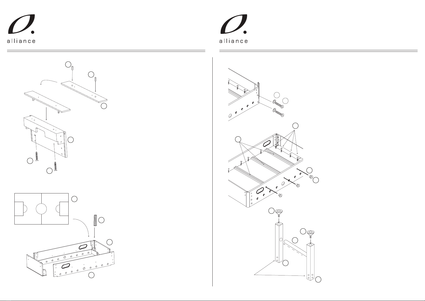
Carmelli
Carmelli HAT TRICK NG1015H Assembly instructions

Bay-Tek
Bay-Tek Skee Ball 1908 Alley Service manual

Aristocrat Technologies
Aristocrat Technologies Mars X Upright Service manual

NAMCO
NAMCO Ridge Racer V Arcade Battle Operator's manual