ALLIGATOR sens.it RetroFIT-kit 2.0 User manual

1
Operating manual
Thank you for purchasing this ALLIGATOR sens.it tyre pressure monitoring system. We
wish you safe and pleasant travels at all times with your new RetroFIT kit.
Contents
Warning notices.................................................................................................................. 2
1.1 General information ............................................................................................... 2
1.2 Precautionary measures when driving................................................................... 3
Scope of supply .................................................................................................................. 4
Display commissioning........................................................................................................ 5
1.3 Insertion of the battery........................................................................................... 5
1.4 Installing the display in the vehicle......................................................................... 6
Sensor and valve installation .............................................................................................. 7
Operation and function........................................................................................................ 8
1.5 Explanation / button functions................................................................................ 8
Display operation................................................................................................................ 9
1.6 Switch-on process.................................................................................................. 9
1.7 Initial learning process........................................................................................... 9
1.7.1 No communication with the sensor................................................................ 10
1.8 Switching off the display ...................................................................................... 11
1.9 Switching between pressure and temperature..................................................... 11
1.10 Display in alarm status...................................................................................... 11
1.10.1 Air pressure undercut (threshold value)..................................................... 11
1.10.2 Temperature too high................................................................................. 12
1.10.3 Display / receiver battery weak .................................................................. 12
1.10.4 Sensor battery status critical...................................................................... 12
1.11 Display menu guidance .................................................................................... 13
1.12 Learning............................................................................................................ 15
Product specifications....................................................................................................... 17
Safety and general information......................................................................................... 18

2
Warning notices
Since this tyre pressure monitoring system communicates wirelessly, signal
interference can occur with the operating manual is disregarded or commissioning is
carried out incorrectly.
Devices that radiate airwaves or radio waves can interfere with the receiver,
which can cause a malfunction of the system despite correct installation.
If a malfunction occurs, please attempt to re-learn the system or increase the distance
between the possible sources of error (the interfering devices) and the system.
The tyre pressure must be filled and/or tested at room temperature (20 - 25°C)
according to the recommendations of the vehicle manufacturer.
1.1 General information
•Please keep this operating manual for later reference.
Please always observe the following precautionary measures:
•Store the RetroFIT kit in a suitable environment. It must not be exposed to
excessive humidity or in direct sunlight.
•Never attempt to dismantle components of your RetroFIT kit. Only clean the device
with a dry or damp, soft cloth. In the process, do not use any chemical solvents
such as brake cleaner, acetone, IPA, thinners, alcohol or similar substances,
because this can damage the plastic surface under certain circumstances.

3
1.2 Precautionary measures when driving
Do not carry out any activities on the system, such as adjustments, during travel, which
could distract you from the traffic situation.
ALLIGATOR Ventilfabrik GmbH assumes no liability for any losses or claims of third
parties based on inattentiveness due to such system operation.
The manufacturer is unable to monitor to ensure observance of this manual and the
conditions and methods for installation, operation, use and maintenance of the
RetroFIT kit. Improperly performed installation can result in damage and endanger
persons as a result.
Therefore, ALLIGATOR assumes no responsibility or liability in any manner for losses,
damages or expenses related to defective installation, improper operation or incorrect
use and maintenance. Furthermore, ALLIGATOR assumes no responsibility for the
rights of third parties of any type. The manufacturer reserves the right to modify the
product, the technical data or assembly and operating instructions without prior
notification.
Opening of the product, attempts at manipulation or repair and unintended operation
render the warranty void.
ALLIGATOR assumes no liability and assumes no guarantee, expressly or implicitly, in
regard to the information contained in the operating manual.
This operating manual was created with the greatest care. Nevertheless, if it should
contain errors or ambiguous formulations, please notify the dealer from which you
purchased the device.
Conformity with the Directives of the European Union:
this device complies with the requirements for CE marking and the related
requirements of Directive R & TTE (EU Directive 1999/5/EC).
4
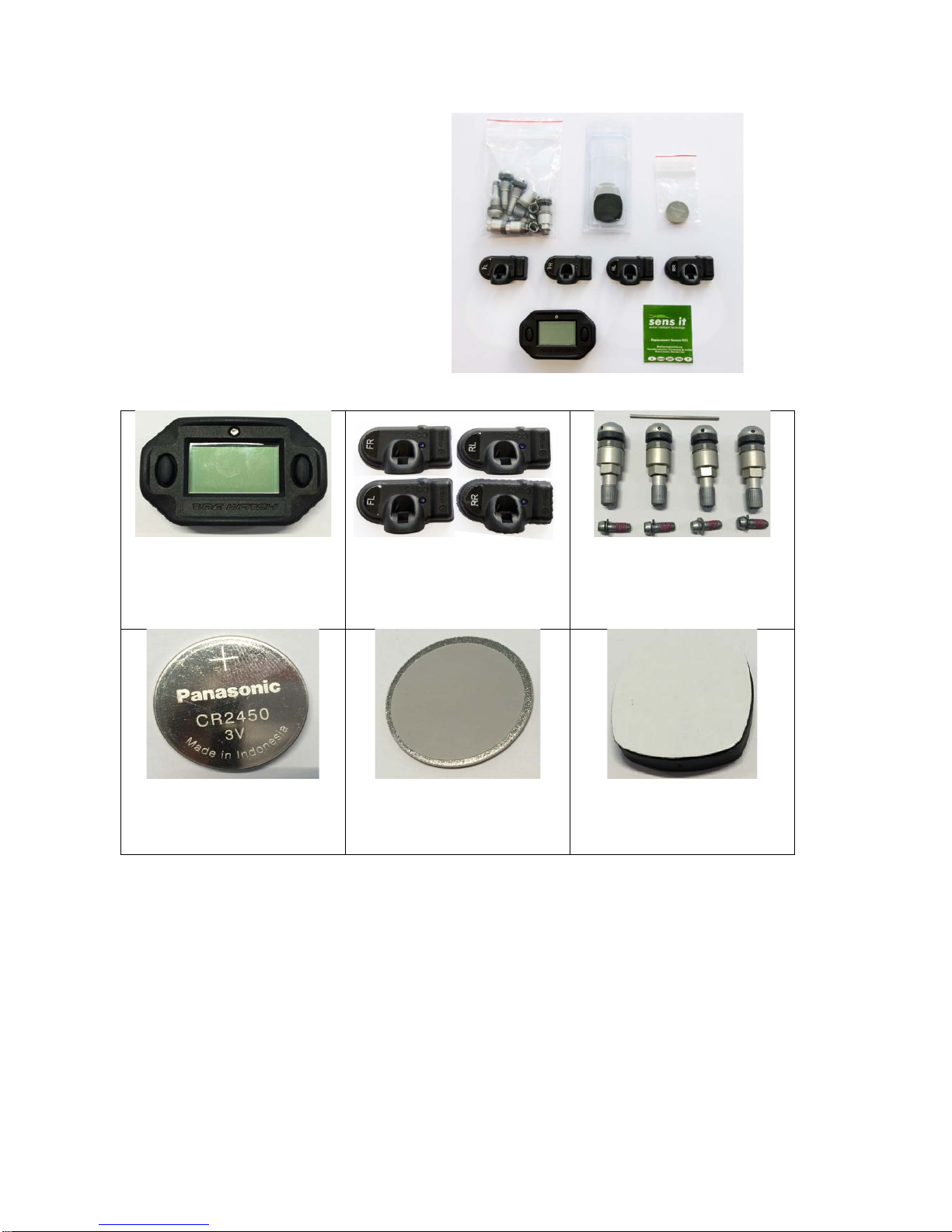
Scope of supply
- 1 Display
- 4 TPM sensors
- 4 valves
- 1 CR2450 battery
- 1 RetroFIT Kit operating manual
- 1 Sensor operating manual
1x Display
4x Sensor
4x Valve
4x Valve screw
1x Assembly aid
1x Button cell (battery)
Type: CR2450 3V
1x Mounting plate
(for fastening in the vehicle
including adhesive strips)
1x Magnet
(for fastening of the display,
including adhesive strips)

5
Display commissioning
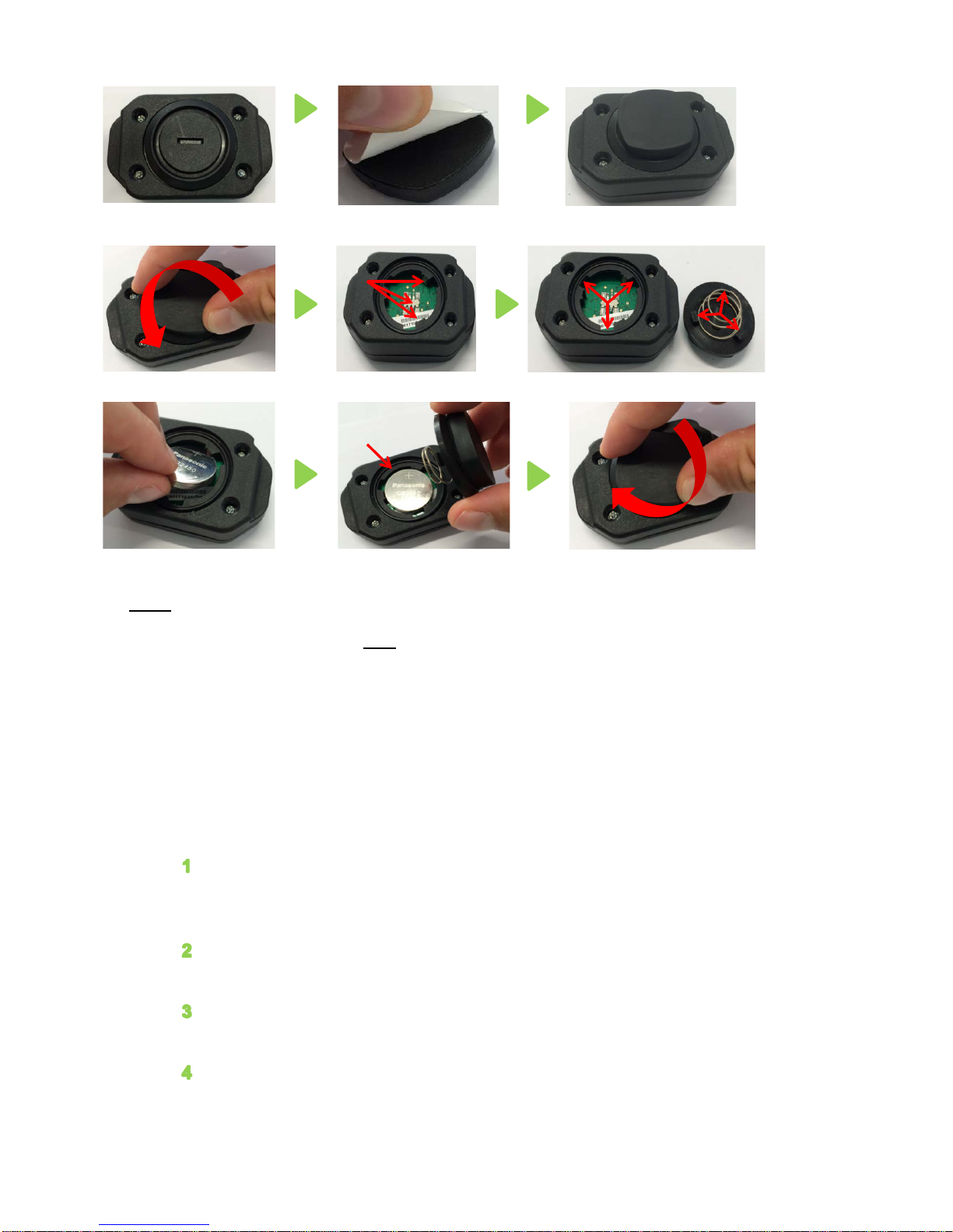
1.3 Insertion of the battery
Proceed as follows to open the battery compartment of the display:
In order to achieve the best possible adhesive effect, clean the back side of
the display so that it is completely free from dirt, silicone, wax, etc. (Figure 1)
Now remove the protective film on the self-adhesive side of the magnet
(Figure 2)
Centre the magnet on the back side of the display and press it gently on the
surface for about 30 seconds (Figure 3)
To open the battery compartment, turn the cover of the battery compartment
on the back side of the display unit anti-clockwise. (Figure 4)
Now take the button cell (battery) included in the scope of supply and insert it
in the display. (Figure 7) (When replacing the battery, please use an
equivalent button cell of the type CR2450).
Please observe the following when inserting the battery:
- There contacts must be free from dirt. (Figure 5)
- The contact points must not have any deformation (Figure 5)
- The battery must be inserted so that the + pole faces towards you (Figure
7)
- The seal (O-ring) must be present on insertion (Figure 8)
Gently press the cover in place. The cover must be positioned so that he
locking logs fit in the matching recesses on the back side of the display
housing.(Figure 6) Then turn the cover clockwise to lock. (Figure 9)
6
Note:
The RetroFIT kit display must only be opened in the scope of battery replacement or
for the initial commissioning. Proceed in strict compliance with the instructions under
"Display - Initial steps / battery replacement". Any deviation renders all warranty claims
void. Opening of the other products included in the scope of supply, attempts at
manipulation or repair and unintended operation render the warranty void.
Note: Battery replacement for the sensors is not possible.
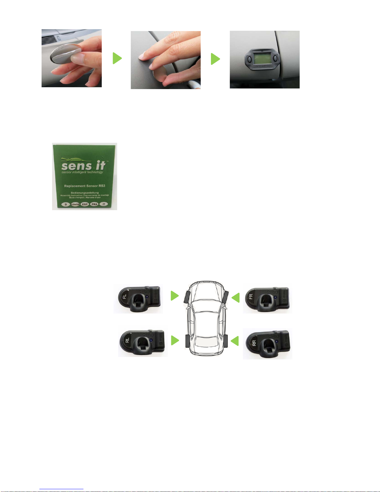
1.4 Installing the display in the vehicle
Proceed as follows to mount the display in the vehicle:
In order to achieve the best possible adhesive effect in the following step,
attempt to fasten the mounting plate on a level surface on the instrument
panel. Please ensure that the surface is free from dirt, silicone, wax, etc.
Now remove the protective film on the self-adhesive side of the mounting
plate. (Figure 10)
Now press the mounting plate on the selected area and apply pressure for
approx. 30 seconds. (Figure 11)
Now the rear side of the display can be fastened on the magnet positioned
on the mounting plate. The display is now held in place on the mounting
plate by the magnetic force. (Figure 12)
1
2
3
4
5
7
8
6
9
7
Sensor and valve installation
Proceed as described in the supplied "RS3 Sensor Operating Manual" (Figure 14) for
sensor and valve installation.
After installation of the sensor and valve, position the tyres on the vehicle as shown in
Figure 15
FL = front left
FR = front right
RL = rear left
RR = rear right
10
11
12
15
14

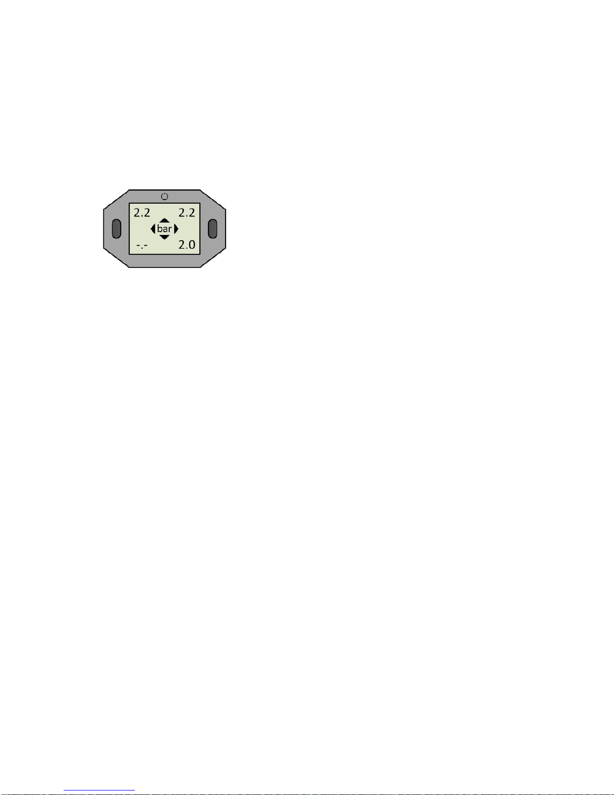
8
Operation and function
1.5 Explanation / button functions
Bt1
Button 1
1) Short press to switch on the device
2) Long press to open the menu
Bt2
Button 2
1) Short press to switch on the device
2) Long press to switch off the device
3) Menu guidance
a
Front left pressure / temperature display
b
Rear left pressure / temperature display
c
Front right pressure / temperature display
d
Rear right pressure / temperature display
e
Warning lamp for tyre pressure
f
Unit of measure: Bar/PSI, °C / °F
g
Display battery voltage status
a
e
c
g
b
f
d
Bt2
Bt1

9
Display operation
1.6 Switch-on process
Briefly pressing Bt1 or Bt2 switches on the display.
The display is then in the initial learning mode or monitoring mode. Monitoring mode is
recognisable by the clockwise-rotating arrow.
Attention! Switch on the display before each drive, because it only provides warnings
when switched on.
1.7 Initial learning process
Requirement:
All 4 sensors have been mounted in the appropriate tyres and each has been mounted in
the correct position on the vehicle as shown in Figure 15.
Attention! For the initial learning process, the display must be in its condition as supplied.
(No sensors have been learned in the display)
This is recognisable by the blinking of all four positions on the CAL display.
If the display learning process has already taken place, please proceed with the steps in
chapter 1.12
Learning:
For the learning process, please drive for at least 10 minutes at a speed in excess of 20
km/h.
Example:
CAL=calibration (learning mode)
Pressure values are received
Received sensor pressure values are
displayed
10
The learning process is successfully completed when the display automatically switches
back to monitoring mode and the arrow rotates clockwise.
The pre-adjusted limit values (air pressure warning) are at 1.8 bar. They can be changed
as described in chapter 1.11, steps 1 - 4.
1.7.1 No communication with the sensor
If the teaching process is interrupted and/or not completed due to signal interference, etc.,
the display switches off. Restart the learning process; refer to chapter 1.6 and 1.7.
11
Bt2
1.8 Switching off the display
1) Switching off manually:
- Press and hold button Bt2 for 3
seconds to switch off the display
2) Switching off automatically:
- The display switches off
automatically after 8 minutes if no
wheel movements are detected
during this time
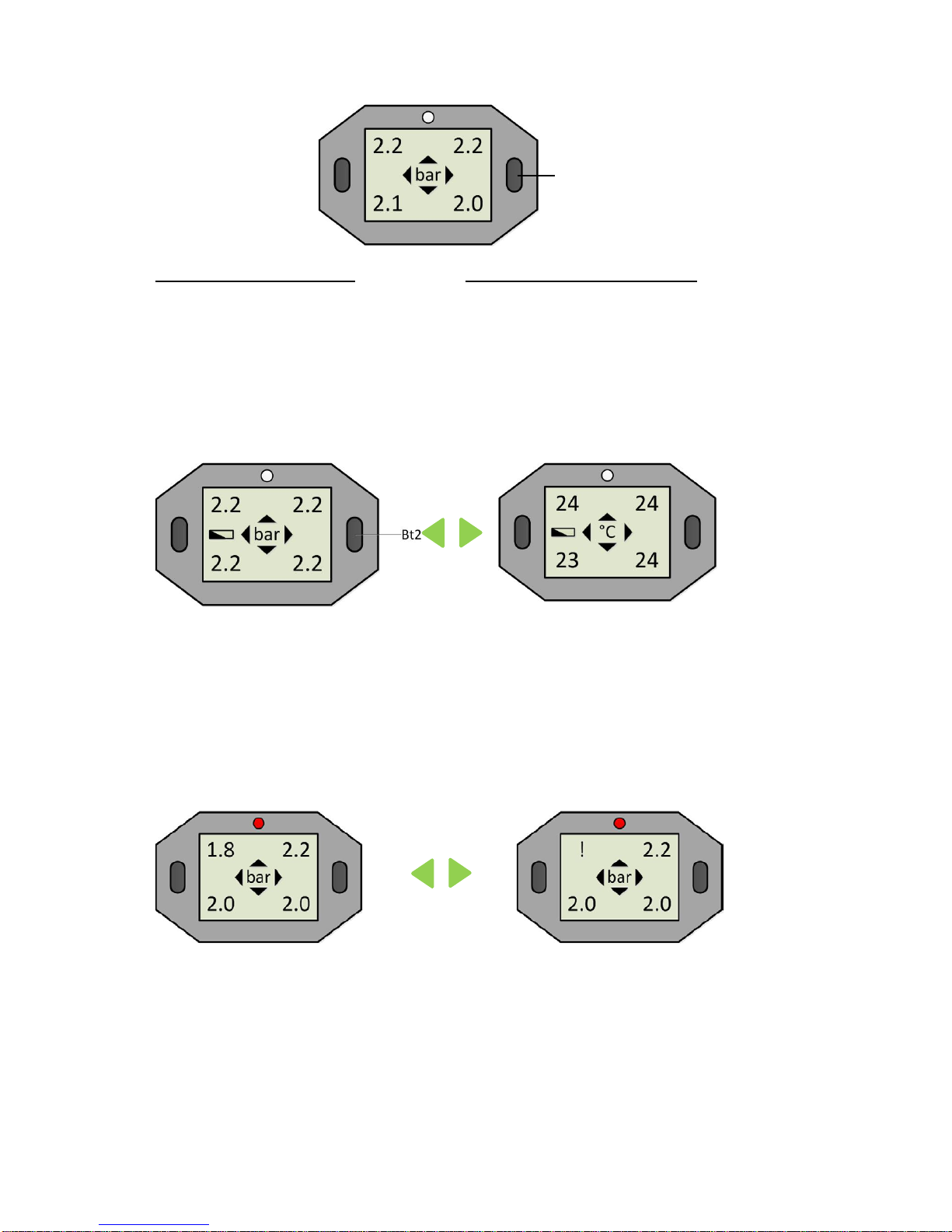
1.9 Switching between pressure and temperature
- To switch between pressure and temperature display, briefly press button Bt2
- The display automatically switches back to the pressure display after approx. 10
seconds (temperature and pressure are displayed for each wheel position)
1.10 Display in alarm status
1.10.1 Air pressure undercut (threshold value)
If the receiver recognises lower pressure values than the adjusted threshold values
(see Table Step 3), the alarm diode blinks for approx. 10 seconds.
The current pressure blinks alternatingly with an exclamation mark (!) at the
relevant position for as long as the threshold value is undercut.
\| /
--
/ | \
\| /
--
/ | \
12
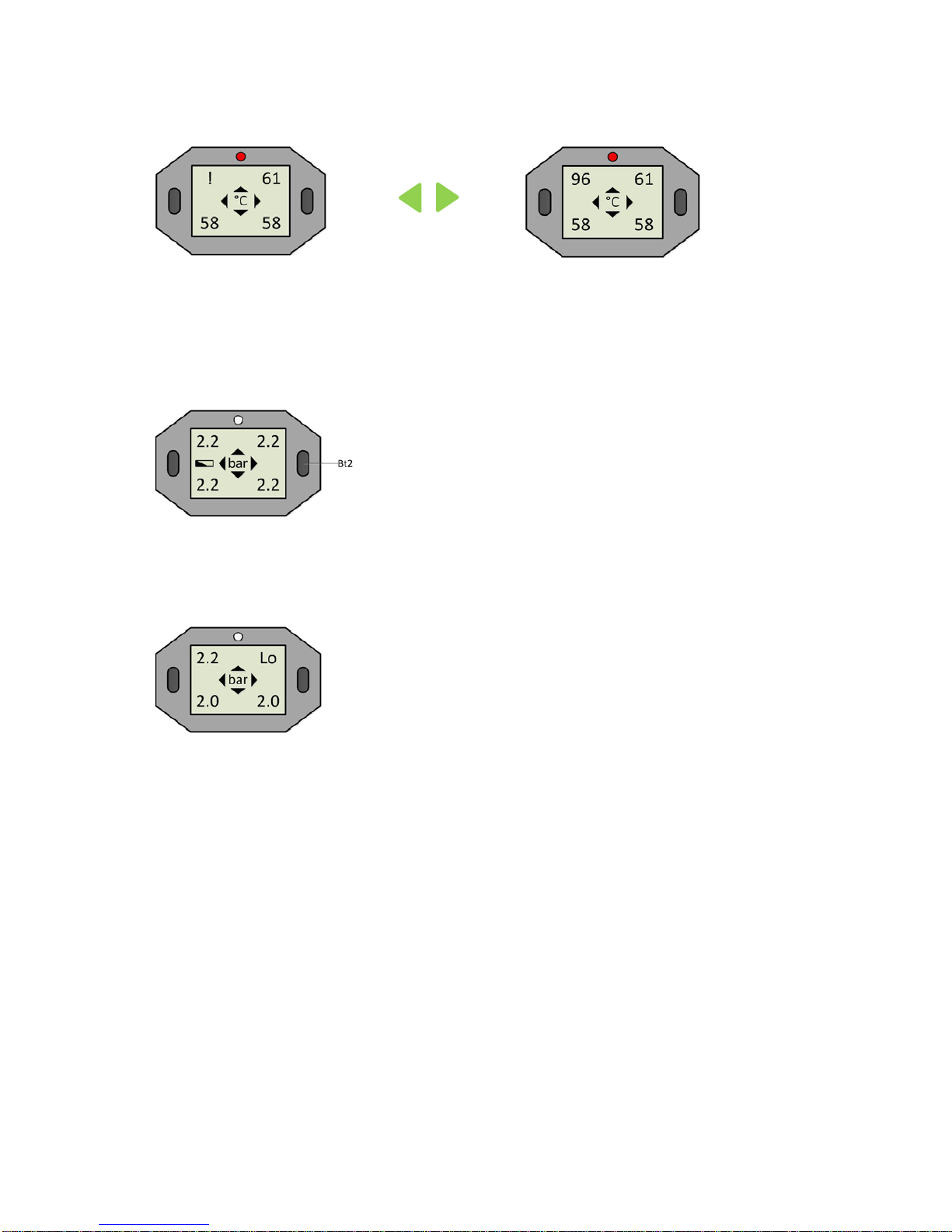
1.10.2 Temperature too high
If a temperature of 95°C is exceeded, the alarm diode blinks for 10 seconds.
The current temperature value blinks alternatingly with an exclamation mark (!) at
the relevant position for as long as the threshold value is exceeded.
1.10.3 Display / receiver battery weak
If the battery voltage reaches a critical value, the battery symbol blinks
continuously. Please replace the battery (type CR2450) as soon as possible.
1.10.4 Sensor battery status critical
If "Lo" appears at a tyre position on the display, please contact a tyre specialist
company or workshop to replace the sensor.
If the outside temperature is below 10°C, this message can be disregarded. Once
the temperature rises above 10° C, the system will work again in the accustomed
manner.
\| /
--
/ | \
\| /
--
/ | \

13
1.11 Display menu guidance
The display is in monitoring mode after switching on, chapter 1.6
Step 1: Settings
Please press and hold button Bt1 to enter the settings.
The display switches back to monitoring mode after approx. 4 minutes without actuation of
a button.
Step 2: Pressure and temperature
a) Select pressure unit
For bar briefly press Bt1 twice
For PSI briefly press Bt2 then briefly press Bt1 twice
b) Select temperature unit
For °C briefly press Bt1 twice
For °F briefly press Bt2 then briefly press Bt2 twice
Confirm by pressing Bt1
twice briefly
Confirm with Bt1
Change the pressure unit (bar/PSI)
by briefly pressing button Bt2
Change the temperature unit (C°/F)
by briefly pressing button Bt2
Confirm by
pressing Bt1
twice briefly
Confirm with Bt1
14
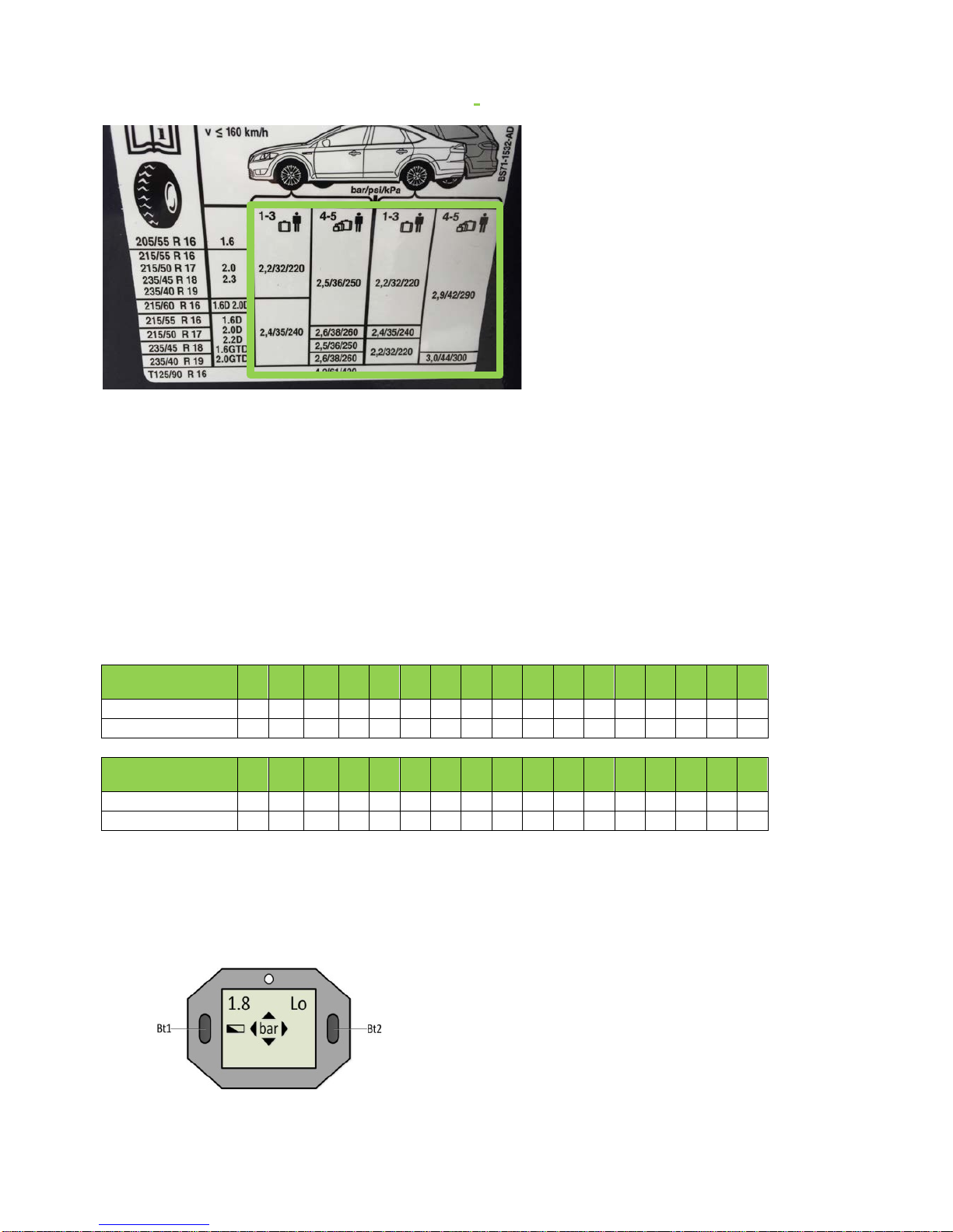
Step 3: Minimum pressure (select limit value)
Please use the pressures recommended by the vehicle manufacturer for the setpoint for
the adjustment of limit values. This is usually provided on the inside of the fuel door, on the
driver door or on the B-column. If you cannot find it there, please refer to your owner's
manual for help.
Pressure setpoint: Tyre pressure recommended by the manufacturer (Figure 16)
Limit value - 20%: Based on the European Directive ECE-R64, we recommend adjusting
the limit value so that an alarm message is issued with a pressure loss
of 20% or a minimum pressure of 1.5 bar at the latest.
The limit value must always be less than the pressure setpoint so that the system issues a
warning.
Pressure setpoint
(bar)
1.9
2.0
2.1
2.2
2.3
2.4
2.5
2.6
2.7
2.8
2.9
3.0
3.1
3.2
3.3
3.4
3.5
Limit value - -10%
1.7
1.8
1.9
2.0
2.1
2.2
2.3
2.3
2.4
2.5
2.6
2.7
2.8
2.9
3.0
3.1
3.2
Limit value - -20%
1.5
1.6
1.7
1.8
1.8
1.9
2.0
2.1
2.2
2.2
2.3
2.4
2.5
2.6
2.6
2.7
2.8
Pressure setpoint
(psi)
28
29
30
31
32
33
34
35
36
37
38
39
40
41
42
43
44
Limit value - -10%
25
26
27
28
29
30
31
32
32
33
34
35
36
37
38
39
40
Limit value - -20%
22
23
24
25
26
26
27
28
29
30
30
31
32
33
34
34
35
Step 4: Limit value (alarm) adjustment
- Press and hold Bt1 to enter the settings.
- Press Bt1 repeatedly until LO appears in the top right of the display.
- First the limit values of the front axle that were specified in Step 3 are adjusted. Then the
process is carried out for the rear axle.
16

15
- The pre-decimal position of the pressure display begins to blink after you briefly press
Bt1.
- Now press Bt2 repeatedly until the pre-decimal position has reached the selected limit
value.
- Now press Bt1 again to select to decimal place.
- Now press Bt2 repeatedly to adjust the selected limit value for the decimal place.
- Press Bt1 to confirm the entry.
- Now proceed analogously for the rear axle (as described above).
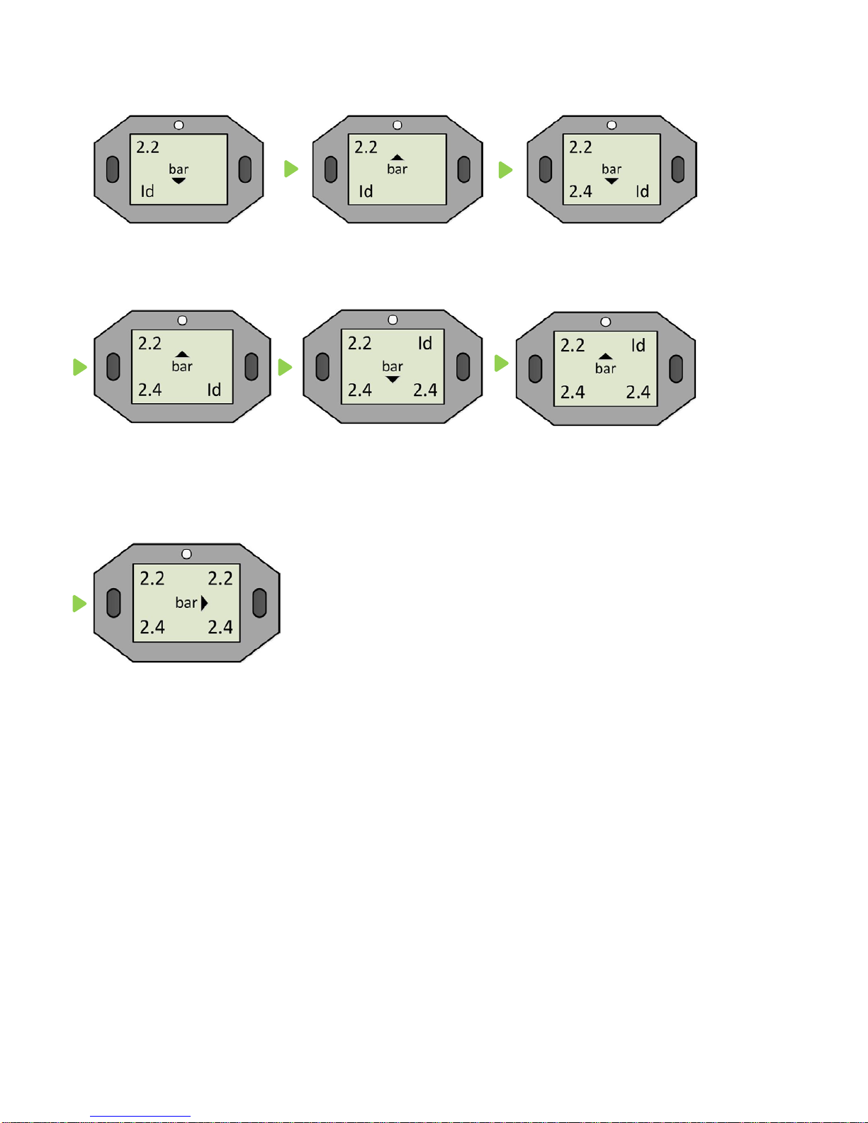
1.12 Learning
Step 5 Learning process for sensor replacement
e.g. in case of wheel replacement
- Press and hold Bt1 to enter the settings.
- Press Bt1 repeatedly until "ID" is displayed at all four positions
- Press Bt2 and the display "ID" appears for the front left with an arrow pointing down (
).
- Hold the display near the front left wheel and release air until the arrow pointing down
disappears. Open (press) the valve insert to release air (see Figure 17)
- Then an arrow pointing up appears ( ). If this is the case, fill the tyre to the specified
normal fill pressure (pressure setpoint) indicated in the vehicle owner's manual.
- Repeat the process in anticlockwise motion for the remaining tyres
1. FL = front left
2. RL = rear left
3. RR = rear right
4. FR = front right
17
16
Example (RL -> RR -> FL):
wait for RL pressure reduction
Fill to normal pressure
wait for RR pressure reduction
Fill to normal pressure
wait for FR pressure reduction
Fill to normal pressure
The learning process is successfully completed when the display automatically switches to
pressure display mode and the arrow rotates clockwise.

17
Product specifications
Receiver (display)
Reception frequency
434Mhz
Operating temperature
-5°C ~ +50°C
Battery
Button cell: CR2450
Size (LxWxH)
approx. 70x45x23mm
Weight
approx. 85g
TPMS sensor
Transmission frequency
434Mhz
Pressure range
0 ~ 8 Bar (0 ~ 116 PSI)
Operating temperature
-30°C ~ +105°C
Size
approx. 48x25x21mm
Weight
approx. 18g
Valve
For valve hole
11.3mm +0.4mm
Length
43mm
Colour
Anodised silver
Material
Aluminium
Weight
approx. 14g

18
Safety and general information
The RetroFIT kit is an information system, not a safety system. ALLIGATOR shall not be
liable, in any way whatsoever, for any and all damages which might be caused if Customer
and/or Customer's drivers of vehicles equipped with the RetroFIT kit should ignore or
misinterpret information provided by it and/or violate their duties to exercise due care
imposed on them by any road traffic regulations that may be applicable at the place of
operation.
Precautionary measures:
•Never mount the display directly on a metallic surfaces due to the risk of signal
interference.
•Never clean the system with a pressure washer.
A damp microfibre cloth is recommended for cleaning.
•Never expose the display to direct sunlight.
•Do not attempt to repair the system on your own. This must be carried out by
qualified and technically trained personnel; otherwise the warranty is voided.
The button cell (battery) contained in the product must be disposed of
separately from the household waste and recycled in accordance with
local statutes and regulations. In doing so, you are making an active
contribution to protection of the environment.
Warning: Never dispose of a battery by burning it
- it could explode.
ALLIGATOR Ventilfabrik GmbH
Richard-Steiff-Straße 4
89537 Giengen/Brenz
sens.it Hotline
Tel.: +49 (0)7322 130 415
Email:europe@alligator-sensit.com
Internet: www.alligator-ventilfabrik.de
Table of contents


