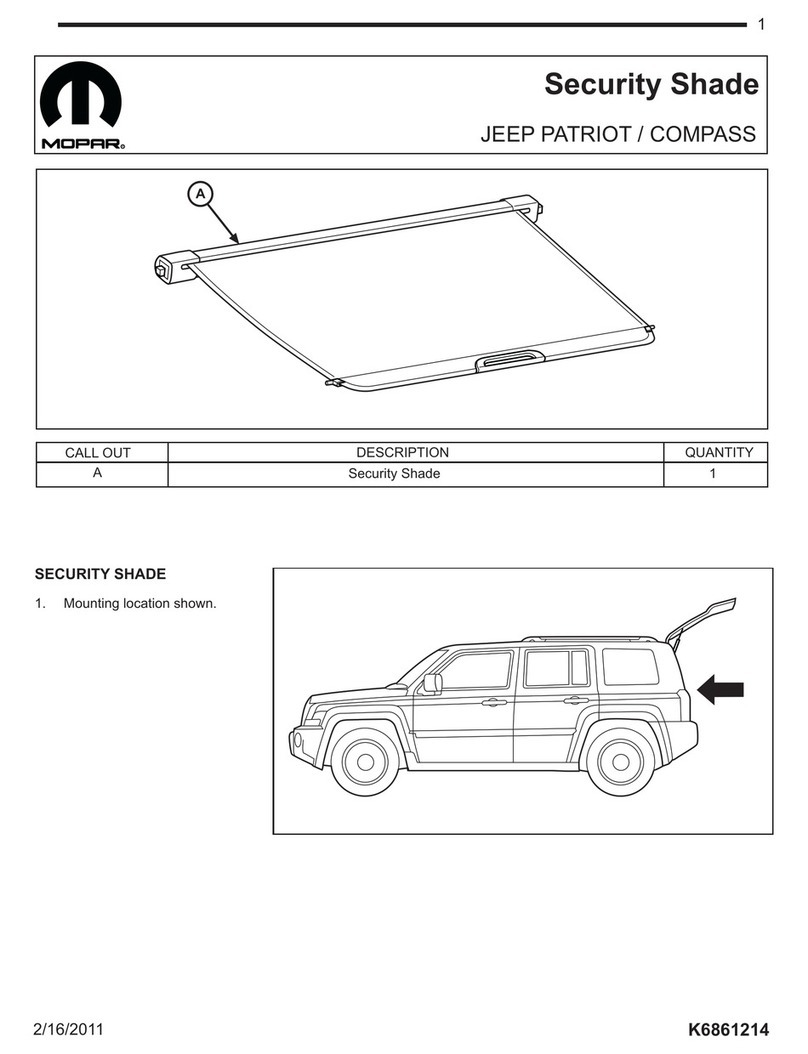
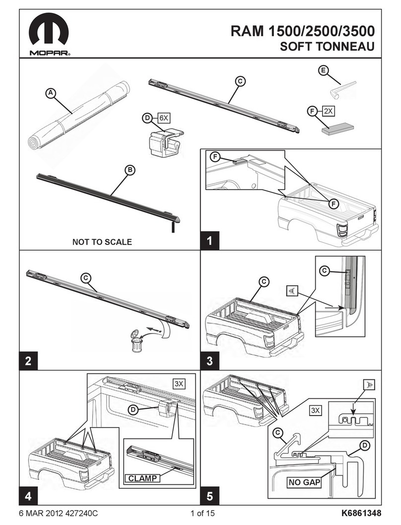
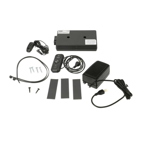
Mopar 82212162 User manual

K6860918i12/15/09
82212162 FLO TV FOR PRODUCTION OVERHEAD DVD
(OR MOPAR EQUIVALENT)
Contents
Click on the desired vehicle to take you directly to the vehicle
specic instructions.
2008 Caravan
2008 Town and Country
2008 Commander
2008 Grand Cherokee
2009 Dodge Ram 1500
2010 Dodge Ram 2500
2010 Dodge Ram 3500
2009 Journey
2007 Nitro

K68609181 of 13
FLO TV FOR PRODUCTION OVERHEAD DVD
(OR MOPAR EQUIVALENT)
12/15/09
CARAVAN
TOWN & COUNTRY
2008
2008
TOOLS REQUIRED:
11MM
KIT CONTENTS:
HARDWARE KIT CONTENTS:
Antenna
FLO TV Module
Main Harness
Wireless
Remote
Wired Remote
Batteries (x2)
Antenna Tail
15 8” cable ties
2 17” cable ties
2 Double sided tape
5 Rubber tubes
1 Hook and loop fastener
2 Foam tape sheet
1 Edge guard
QTY DESCRIPTION
For technical assistance, service replacement
parts, or customer service call:1-800-34-MOPAR
BACK TO CONTENTS
PRINT

K68609182 of 1312/15/09
FLO TV FOR PRODUCTION OVERHEAD DVD
(OR MOPAR EQUIVALENT)
CARAVAN
TOWN & COUNTRY
2008
2008
Prior to Installation
Care must be taken when installing this accessory to ensure damage does not occur to the vehicle.
The installation of this accessory should follow approved guidelines to ensure a quality installation.
Read entire instructions thoroughly before starting.
This document covers such items as:
• Vehicle Protection (use of covers and blankets, cleaning chemicals, etc.)
• Vehicle Disassembly/Reassembly (panel removal, part storage, etc.)
• Electrical Component Disassembly/Reassembly (battery disconnection, connector removal, etc.)
NOTES:
Removed Parts:
Place all removed parts on a protected surface in an area where they will not be damaged.
Connectors:
When disconnecting connectors, do not pull on the wires; pull on the connectors.
Vehicle Preparation and Protection
1. Set the emergency brake and unlock all vehicle doors.
2. Record all radio presets.
3. Open the hood and apply protective covers to the fender/grill area by the battery.
4. Remove the negative battery cable (Figure 1).
CAUTION: Do not touch the positive terminal with any tool when removing the battery cable.
Figure 1

K68609183 of 13
FLO TV FOR PRODUCTION OVERHEAD DVD
(OR MOPAR EQUIVALENT)
12/15/09
CARAVAN
TOWN & COUNTRY
2008
2008
Interior Component Removal
Disassemble the upper rear header trim
(Figure 2).
1. Using a trim stick C-4755 or equivalent,
remove the two plastic screw covers on either
side to reveal the screws.
2. Using a Phillips screwdriver, remove the two
screws.
3. Using a trim stick C-4755 or equivalent, pry to
remove the upper rear header trim panel.
Disassemble the lower rear scuff plate
(Figure 3).
1. Using a trim stick C-4755 or equivalent, pry to
remove the lower rear scuff plate.
Remove the front driver sill plate and cowl
(Figure 4).
1. Using a trim stick C-4755 or equivalent, pry
the nut cover from the back of the sill plate.
2. Using an 11mm ratchet, remove the nut from
the back of the sill plate.
3. Using a trim stick C-4755 or equivalent, pry
the sill plate up from the door sill and remove.
4. Using a trim stick C-4755 or equivalent, pry
the cowl and remove.
Figure 4
Figure 3
Figure 2

K68609184 of 1312/15/09
FLO TV FOR PRODUCTION OVERHEAD DVD
(OR MOPAR EQUIVALENT)
CARAVAN
TOWN & COUNTRY
2008
2008
Interior Component Removal
(continued)
Remove the driver side rear sill plate
(Figure 5).
1. Using a trim stick C-4755 or equivalent, pry
the driver side rear sill plate up from the door
sill and remove.
Remove the instrument panel lower cover
(Figure 6).
1. Using a Phillips screwdriver, remove the six
plastic retainers (1) from the sides of the lower
cover subassembly (2) (three on either side).
2. Slide the lower cover assembly toward the
rear of the vehicle.
3. Disconnect the vehicle harness connectors
from the back of the lower cover assembly
and remove the lower cover assembly.
Disassemble the left rear quarter trim
panel
1. For ease of installation we recommend
unscrewing and partially removing left rear
quarter trim panel to gain access to aux plate.
The plate is held in very tightly by upper two
clips especially. Proceed to disassemble the
driver side rear aux plate as per the procedure
below.
Disassemble the driver side rear aux plate
(Figure 7).
1. Using a trim stick C-4755 or equivalent, pry
the rear aux plate from the side panel at the
four clip locations (1).
2. Disconnect the vehicle harness connectors
and remove the rear aux plate.
Figure 5
Figure 6
Figure 7
1
1
2
1
1
1
1

K68609185 of 13
FLO TV FOR PRODUCTION OVERHEAD DVD
(OR MOPAR EQUIVALENT)
12/15/09
CARAVAN
TOWN & COUNTRY
2008
2008
Interior Component Removal
(continued)
Disassemble passenger side A-pillar
(Figure 8).
1. Using a trim stick C-4755 or equivalent,
remove the two plastic trim covers from the
A-pillar trim.
2. Using a Phillips screwdriver, remove the two
screws from the A-pillar trim.
3. Using a trim stick C-4755 or equivalent,
gently pry off the A-pillar trim.
4. Using a small screwdriver or equivalent,
press downward disengaging the tether clip
and slide from the housing (Please refer to
the Factory Service Manual for tether clip
procedure). Figure 8

K68609186 of 1312/15/09
FLO TV FOR PRODUCTION OVERHEAD DVD
(OR MOPAR EQUIVALENT)
CARAVAN
TOWN & COUNTRY
2008
2008
Installing the Antenna
Mount the antenna (Figure 9).
NOTE: You must keep the antenna at least four
inches from all objects.
NOTE: Once attached, the antenna cannot be
easily removed.
1. Clean the passenger side rear roof between
the two passenger side roof bows with a
MOPAR approved cleaner and cleaning
method.
When cleaning with a MOPAR approved
cleaner and cleaning method:
a. Always use a clean (lint free scratch
resistant) soft cloth (or wipe), and clean a
small area at a time (~ 3 ft. x 3 ft. max.).
b. Shake well and apply MOPAR approved
cleaner to cloth or wipe. Do not spray
cleaning solution directly on vehicle
surfaces.
c. Clean surface thoroughly and wipe dry
immediately with a new clean cloth. Do not
allow cleaner to air dry.
2. The antenna will be positioned 20mm to the
left of the passenger side roof bow as shown.
Before removing the protective adhesive tape
backing from the antenna and antenna tail,
position the antenna and antenna tail on the
roof in the desired mounting location. The
edge of the antenna tail should align with the
roof edge for a clean installation. Verify that
the antenna and antenna tail are positioned
in the desired location and mark the mounting
location with tape (Figure 9).
3. Peel the adhesive tape from the antenna and
antenna tail. Adhere the antenna and antenna
tail to the marked mounting location on the
roof (Figure 9).
Figure 9

K68609187 of 13
FLO TV FOR PRODUCTION OVERHEAD DVD
(OR MOPAR EQUIVALENT)
12/15/09
CARAVAN
TOWN & COUNTRY
2008
2008
Route the antenna cable.
1. Run the antenna cable near the passenger
side hatch hinge and secure in place using 3
pieces of foam tape (Figure 10).
2. Pull back the rubber door seal and install the
Edge Guard provided in the hardware kit over
the door opening, as shown (Figure 11).
3. Route the antenna cable diagonally over the
Edge Guard and then place a piece of foam
tape over the antenna cable (Figure 11).
4. Reinstall the rubber door seal over the Edge
Guard.
5. Route the antenna cable under the headliner
and toward the passenger side of the vehicle
(Figure 12).
6. Continue routing the antenna cable, tucking
it behind the passenger side D-pillar (Figure
12).
7. Continue routing the antenna cable, down
towards the lower scuff plate (Figure 12).
8. Route the antenna cable towards the driver
side of the vehicle under the lower scuff plate
(Figure 12).
Figure 12
Figure 10
Figure 11

K68609188 of 1312/15/09
FLO TV FOR PRODUCTION OVERHEAD DVD
(OR MOPAR EQUIVALENT)
CARAVAN
TOWN & COUNTRY
2008
2008
Figure 14
Route the antenna cable (continued)
(Figure 13).
9. Route the antenna to the aux jack location.
10. Secure all cabling along the route using foam
tape and wire ties, as needed.
Installing the Wired Remote Control and
Antenna Receiver
NOTE: Please leave enough remote control
wire in the glove box to allow the remote control
to be comfortably held and operated by vehicle
occupants.
NOTE: Route the antenna receiver cable away
from the airbag, airbag wiring and airbag tether
behind the A-pillar.
NOTE: Do not attach the antenna receiver cable
to the airbag, airbag wiring or airbag tether behind
the A-pillar.
1. The antenna receiver on the wired remote
control assembly will be positioned on the
windshield centered above the rear view
mirror. For optimal performance, the antenna
receiver should be positioned at least two
inches below the headliner (Figure 14).
2. Clean the windshield with a MOPAR
approved cleaner and cleaning method.
When cleaning with a MOPAR approved
cleaner and cleaning method:
a. Always use a clean (lint free scratch
resistant) soft cloth (or wipe), and clean
the area.
b. Shake well and apply MOPAR approved
cleaner to cloth or wipe. Do not spray
cleaning solution directly on vehicle
surfaces.
c. Clean surface thoroughly and wipe dry
immediately with a new clean cloth. Do
not allow cleaner to air dry.
3. Before removing the protective adhesive
tape backing from the antenna receiver,
position the antenna receiver on the desired
windshield mounting location. Verify that the
antenna receiver is positioned in the desired
location and mark the mounting location with
tape.
Figure 13

K68609189 of 13
FLO TV FOR PRODUCTION OVERHEAD DVD
(OR MOPAR EQUIVALENT)
12/15/09
CARAVAN
TOWN & COUNTRY
2008
2008
Figure 15
Installing the Wired Remote Control and
Antenna Receiver (continued) (Figure 15).
4. Peel the protective adhesive tape from the
antenna receiver and adhere the antenna
to the windshield in the marked mounting
location (Figure 14).
5. Route the antenna receiver cable under the
headliner and towards the passenger side
A-pillar (Figure 14).
6. Continue routing the antenna receiver cable
down the A-pillar towards the glove box area
(Figure 14).
7. Remove the protective backing from the hook
and loop fastener. Attach the loop side of
the fastener to the back of the wired remote
control. Attach the hook side of the fastener
to a location in the glove box that will secure
the remote control, preventing accidental
button activation.
8. Route the remote control cable from the glove
box to the lower instrument panel (Figure 15).
9. Route the remote control cable under the
carpetacrossthedriversideoorboard
(Figure 15).
10. Continue routing the wired remote control
cable down the driver side front sill plate
towards the rear of the vehicle (Figure 16).
11. Continue routing the remote control cable
down the driver side rear sill plate towards
the rear of the vehicle and into the aux jack
location (Figure 17).
12. Secure all cabling along the route using
foam tape and wire ties, as needed.
NOTE: Image shown with seats removed for
locator view only. Figure 17
Figure 16

K686091810 of 1312/15/09
FLO TV FOR PRODUCTION OVERHEAD DVD
(OR MOPAR EQUIVALENT)
CARAVAN
TOWN & COUNTRY
2008
2008
Connecting the Main Harness
Connect the Main Harness (Figure 18).
1. Unplug the factory aux jack connector.
2. Plug the main harness male connector (A) into the
aux jack.
3. Plug the main harness female connector (B) into the
previously unplugged aux jack connector.
Connect power and ground.
NOTE: Cigarette lighter is located in the aux jack plate.
1. Locate the fused ignition switch output wire (LB/PK-
CAV 1) and the ground wire (BK/YL-CAV 3) from
the cigarette lighter connector (Figure 19).
2. Using wire strippers, strip back 1/2” of the wire
jacket from the fused ignition switch output wire
(LB/PK-CAV 1) and the ground wire (BK/YL-CAV 3)
(Figure 20).
3. Usingasmallatbladescrewdriver,pokeahole
through each of the stripped wires (Figure 21).
Figure 19
Figure 18
Figure 20
A
B
Figure 21

K686091811 of 13
FLO TV FOR PRODUCTION OVERHEAD DVD
(OR MOPAR EQUIVALENT)
12/15/09
CARAVAN
TOWN & COUNTRY
2008
2008
Connect power and ground (continued).
4. Insert the red fused wire of the main harness
through the opening and wrap around the
fused ignition switch output wire (Figure 22).
5. Insert the black wire of the main harness
through the opening and wrap around the
ground output wire (Figure 22).
6. Solder each of the wires as shown (Figure 23).
7. Wrap electrical tape around each of the
exposed wires to protect. (Figure 24).
Installing the FLO TV Module
Connect remaining cables (Figure 25).
1. Connect the wired remote control cable (A) to
the FLO TV module.
2. Connect the main harness (B) to the FLO TV
module.
3. Connect the antenna wire (C) to the FLO TV
module.
Mount the FLO TV module (Figure 26).
1. Using two (2) pieces of double side tape,
mount the FLO TV module behind the aux
jacks in the driver side rear aux plate.
Figure 22
Figure 23
Figure 26
Figure 24
A
B
C
Figure 25

K686091812 of 1312/15/09
FLO TV FOR PRODUCTION OVERHEAD DVD
(OR MOPAR EQUIVALENT)
CARAVAN
TOWN & COUNTRY
2008
2008
In Process Functional Test
1. Temporarily reconnect the battery negative cable.
2. Turn ignition key to the ACC position.
3. Press the POWER Button on the Factory RSE unit. Verify that the Factory RSE unit powers on.
4. Change the Source input on the Factory RSE unit to AUX input.
5. Verify that the FLO TV logo or a FLO TV channel is displayed on the Factory RSE unit screen. Upon
powering on, the FLO TV logo will appear on the screen for up to 60 seconds, after which the FLO TV
preview channel is displayed. (NOTE: If no FLO TV video is observed on the screen, press the MODE button
on the wired or wireless remote control to switch between AUX input and FLO TV input.)
6. Press the POWER button on the head unit and verify that the radio turns on.
7. Verify that audio can be heard through the vehicle audio system.
8. Install batteries in the Wireless Remote Control and press the Up and Down Arrows on the Wireless Remote
Control and verify that the wireless remote control changes channels.
9. Press the Up and Down Arrows on the Wired Remote Control and verify that the wired remote control
changes channels.
10. Disconnect the negative battery terminal.
11. Reassemble the vehicle interior components and trim.
Final Preparation
1. Place the owner’s manual and quick start guide in the glove box.
2. Place the wireless remote control in the glove box.
3. Reconnect the negative battery terminal and tighten nut.
4. Reset radio presets.

K686091813 of 13
FLO TV FOR PRODUCTION OVERHEAD DVD
(OR MOPAR EQUIVALENT)
12/15/09
CARAVAN
TOWN & COUNTRY
2008
2008
Figure 27
For technical assistance, service replacement parts, or customer service call:1-800-34-MOPAR

K68609181 of 1212/15/09
FLO TV FOR PRODUCTION OVERHEAD DVD
(OR MOPAR EQUIVALENT)
2008 GRAND CHEROKEE
2008 COMMANDER
TOOLS REQUIRED:
KIT CONTENTS:
HARDWARE KIT CONTENTS:
10MM
15 8” cable ties
2 17” cable ties
2 Double sided tape
5 Rubber tubes
1 Hook and loop fastener
2 Foam tape sheet
1 Edge guard
QTY DESCRIPTION
Antenna
FLO TV Module
Main Harness
Wireless
Remote
Wired Remote
Batteries (x2)
Antenna Tail
For technical assistance, service replacement
parts, or customer service call:1-800-34-MOPAR
BACK TO CONTENTS
PRINT

K68609182 of 1212/15/09
FLO TV FOR PRODUCTION OVERHEAD DVD
(OR MOPAR EQUIVALENT)
2008 GRAND CHEROKEE
2008 COMMANDER
Prior to Installation
Care must be taken when installing this accessory to ensure damage does not occur to the vehicle.
The installation of this accessory should follow approved guidelines to ensure a quality installation.
Read entire instructions thoroughly before starting.
This document covers such items as:
• Vehicle Protection (use of covers and blankets, cleaning chemicals, etc.)
• Vehicle Disassembly/Reassembly (panel removal, part storage, etc.)
• Electrical Component Disassembly/Reassembly (battery disconnection, connector removal, etc.)
NOTES:
Removed Parts:
Place all removed parts on a protected surface in an area where they will not be damaged.
Connectors:
When disconnecting connectors, do not pull on the wires; pull on the connectors.
Vehicle Preparation and Protection
1. Set the emergency brake and unlock all vehicle doors.
2. Record all radio presets.
3. Open the hood and apply protective covers to the fender/grill area by the battery.
4. Remove the negative battery cable (Figure 1).
CAUTION: Do not touch the positive terminal with any tool when removing the battery cable.
Figure 1
Figure 1

K68609183 of 1212/15/09
FLO TV FOR PRODUCTION OVERHEAD DVD
(OR MOPAR EQUIVALENT)
2008 GRAND CHEROKEE
2008 COMMANDER
Interior Component Removal
NOTE: Cover the face of the center console with a
protective blanket during the removal procedure.
NOTE: Place Components and attaching
hardware on a protective blanket outside the
vehicle following removal.
Remove the instrument panel cover.
1. Using a trim stick C-4755 or equivalent, pry
the center console shifter Inner Trim (1)
upward and remove from the center console
(Figure 2).
2. Using a trim stick C-4755 or equivalent, pry
the center console shifter Outer Trim (2)
upward and remove from the center console
(Figure 2).
3. Using a Phillips screwdriver, remove one
screw (1) from the bottom storage tray and
remove the instrument panel (2) (Figure 3).
Remove the center console (Figure 4).
NOTE: Place the center console and attaching
hardware on a protective blanket outside the
vehicle following removal.
1. Remove the cup holder liner (1).
2. Remove the center console rear cover panel
(2).
3. Using a socket driver, remove one bolt (3)
located in the cup holder opening.
4. Using a torx driver, remove the two torx
screws (4).
5. Remove the center console (5).
Figure 2
Figure 3
Figure 4

K68609184 of 1212/15/09
FLO TV FOR PRODUCTION OVERHEAD DVD
(OR MOPAR EQUIVALENT)
2008 GRAND CHEROKEE
2008 COMMANDER
Interior Component Removal
Disassemble the upper and lower rear
header trim panels (Figure 5).
1. Using a trim stick C-4755 or equivalent,
remove the upper and lower rear header trim
panels.
Remove the driver side rear sill plate
(Figure 6).
1. Using a trim stick C-4755 or equivalent, pry
the driver side rear sill plate up from the door
sill and remove.
Disassemble passenger side A-pillar
(Figure 7).
1. Using a trim stick C-4755 or equivalent,
remove the two plastic trim covers from the
A-pillar trim.
2. Using a Phillips screwdriver, remove the two
screws from the A-pillar trim.
3. Using a trim stick C-4755 or equivalent,
gently pry off the A-pillar trim.
4. Using a small screwdriver or equivalent,
press downward disengaging the tether clip
and slide from the housing (Please refer to
the Factory Service Manual for tether clip
procedure).
Figure 5
Figure 6
Figure 7

K68609185 of 1212/15/09
FLO TV FOR PRODUCTION OVERHEAD DVD
(OR MOPAR EQUIVALENT)
2008 GRAND CHEROKEE
2008 COMMANDER
Installing the Antenna
Mount the antenna (Figure 8).
NOTE: You must keep the antenna at least four
inches from all objects.
NOTE: Once attached, the antenna cannot be
easily removed.
1. Clean the driver side rear roof between the
two driver side roof bows with a MOPAR
approved cleaner and cleaning method.
When cleaning with a MOPAR approved
cleaner and cleaning method:
a. Always use a clean (lint free scratch
resistant) soft cloth (or wipe), and clean a
small area at a time (~ 3 ft. x 3 ft. max.).
b. Shake well and apply MOPAR approved
cleaner to cloth or wipe. Do not spray
cleaning solution directly on vehicle
surfaces.
c. Clean surface thoroughly and wipe dry
immediately with a new clean cloth. Do
not allow cleaner to air dry.
2. The antenna will be centered between the
two driver side roof bows. Before removing
the protective adhesive tape backing from
the antenna and antenna tail, position the
antenna and antenna tail on the roof in the
desired mounting location. The edge of the
antenna tail should align with the roof edge
for a clean installation. Verify that the antenna
and antenna tail are positioned in the desired
location and mark the mounting location with
tape (Figure 8).
3. Peel the adhesive tape from the antenna and
antenna tail. Adhere the antenna and antenna
tail to the marked mounting location on the
roof (Figure 8).
Figure 8

K68609186 of 1212/15/09
FLO TV FOR PRODUCTION OVERHEAD DVD
(OR MOPAR EQUIVALENT)
2008 GRAND CHEROKEE
2008 COMMANDER
Route the antenna cable.
1. Run the antenna cable near the driver side
hatch hinge and secure in place using 3
pieces of foam tape (Figure 9).
2. Pull back the rubber door seal and install the
Edge Guard provided in the hardware kit over
the door opening, as shown (Figure 10).
3. Route the antenna cable diagonally over the
Edge Guard and then place a piece of foam
tape over the antenna cable (Figure 10).
4. Reinstall the rubber door seal over the Edge
Guard.
5. Route the antenna cable under the headliner
and toward the driver side of the vehicle
(Figure 11).
6. Continue routing the antenna cable, tucking
it behind the left rear side hatch seal (Figure
11).
7. Route the antenna cable forward to the driver
side rear door sill (Figure 12).
8. Using a wire grabber or equivalent, route the
antenna cable beneath the carpet to the rear
of the center console (Figure 12).
9. Secure the antenna cable using foam tape
and wire ties, as needed.
Figure 11
Figure 12
Figure 10
Figure 9
Table of contents
Other Mopar Automobile Accessories manuals

Mopar
Mopar Sun Bonnet User manual

Mopar
Mopar 82212262 User manual

Mopar
Mopar Jeep Trail Guide User manual

Mopar
Mopar 82212475 User manual

Mopar
Mopar 82207353 User manual

Mopar
Mopar 82214331AB User manual

Mopar
Mopar Sun Bonnet User manual

Mopar
Mopar 2005-2009 Chrysler 300C User manual

Mopar
Mopar 82211442 Series User manual

Mopar
Mopar 82213022AC User manual
Mopar
Mopar UCONNECT Series User manual

Mopar
Mopar 82214995 User manual

Mopar
Mopar 82207513 User manual

Mopar
Mopar 82214679AD User manual

Mopar
Mopar 82215863 User manual

Mopar
Mopar UCONNECT Series User manual

Mopar
Mopar 77072446AB User manual

Mopar
Mopar 82211335AB User manual
Mopar
Mopar 82215446 User manual

Mopar
Mopar K6862677 User manual