ALLIMEX SolarSpeed User manual

MOUNTING INSTRUCTIONS
SolarSpeed
East-West facing landscape
Headquarters: Mijnwerkerslaan 33/3, B-3550 Heusden-Zolder | T. +32 11 72 96 50
Dutch branch: Gladsaxe 45, NL-7327 JZ Apeldoorn | T. +31 857 326 946

BASE 1
Due to the continuous development of our products, a deviation on the image is possible. No rights can be derived from any printing or setting errors.
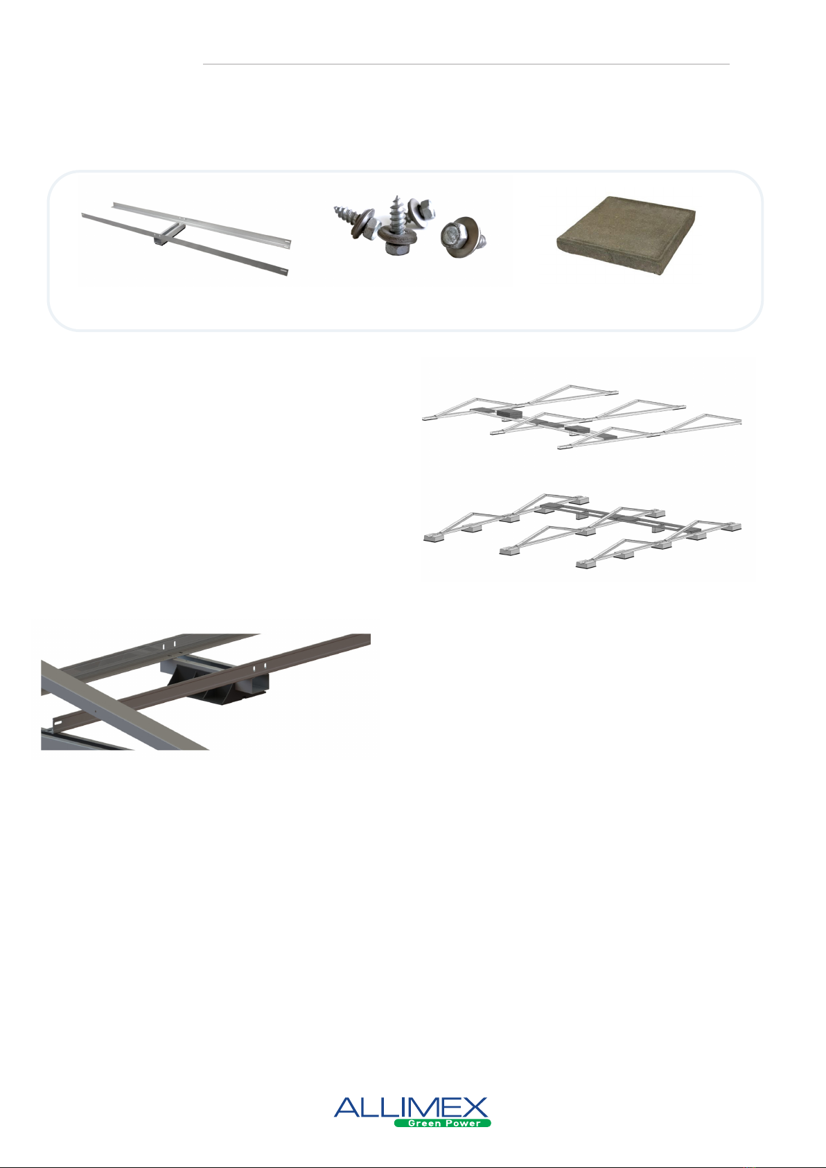
STANDARD PARTS
1
2
3
4
Base-unit: brackets + rail + protective rubber*
Set L-proles + support*
End rubber*
Middle clamps and end clamps + hexagonal socket screws M8
EXTRA PARTS
Alignment tool
Concrete base (12 kg) +
impact anchor
PP-base
Cable tray support
Cable clips
*For PVC roofs we recommend rubber with an aluminium coating.
MOUNTING TOOLS
Cordless drill Socket 8 Hex keys Screwdriver Hammer Chalk line
Pebble stone bin

2
Make sure that the roof surface, where the panels should be installed, is clean, dry and even. Impu-
rities such as gravel, sand and pebbles can cause damage to the roof or instability of the installation.
Due to the continuous development of our products, a deviation on the image is possible. No rights can be derived from any printing or setting errors.
BEFORE THE INSTALLATION
Correcte assembly plate screws
When assembling with a screwdriver: The use of impact wrenches is prohibited. When using a
screwdriver, the rotation speed may not exceed 1500 rpm. The washer must be mounted perpen-
dicularly and not too hard, but also not too little.
Follow all safety measures in accordance with the relevant guidelines before starting the
installation!
insucient
screwing
excessive
screwing
properly screwed
BASE
3
1. MOUNTING BASE UNITS
From semi-mounted to mounted base units
Due to the continuous development of our products, a deviation on the image is possible. No rights can be derived from any printing or setting errors.
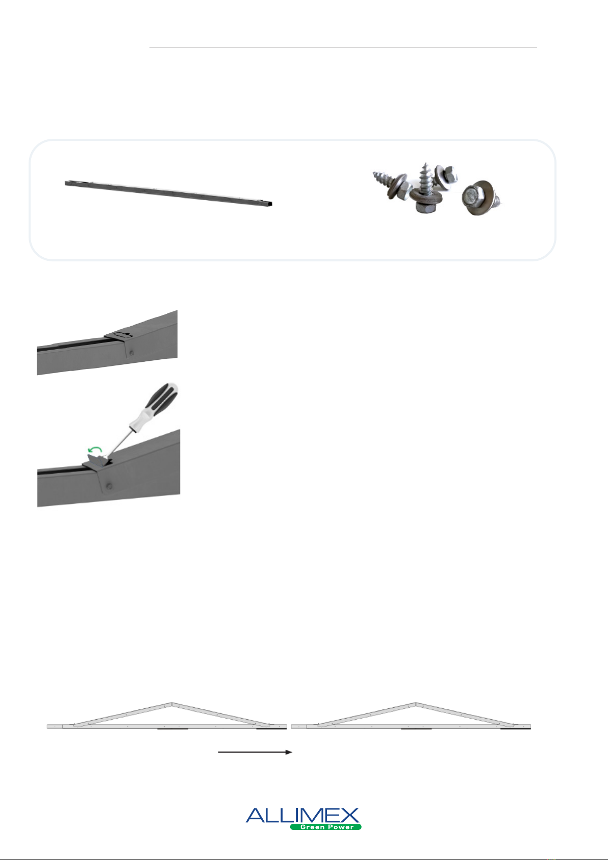
Secure the loose part of the mounting bracket to the rail by means
of plate screws (Ø6.5). When using concrete of PP bases, these
must be secured with poprivets.
SolarSpeed base-unit
semi-mounted
Plate screws
Fold the panel stop using a screwdriver. Fold it further until it forms
an angle of 90 ° to the mounting bracket.
Assembling base units
• Place the base units on a at en stable roof surface.
• Connect the base units by sliding the top of the rail of the rst base unit into the connection piece
at the back of the next base unit.
• Fix by drilling 2 self-tapping screws (Ø6.5) or SS rivets into the pre-drilled holes on the side or on
top of the connection pieces.
• First, attach the connector with rubber protection onto the base units at the end of each row,
before attaching the base units to each other.
INSTALLATION
4
Due to the continuous development of our products, a deviation on the image is possible. No rights can be derived from any printing or setting errors.
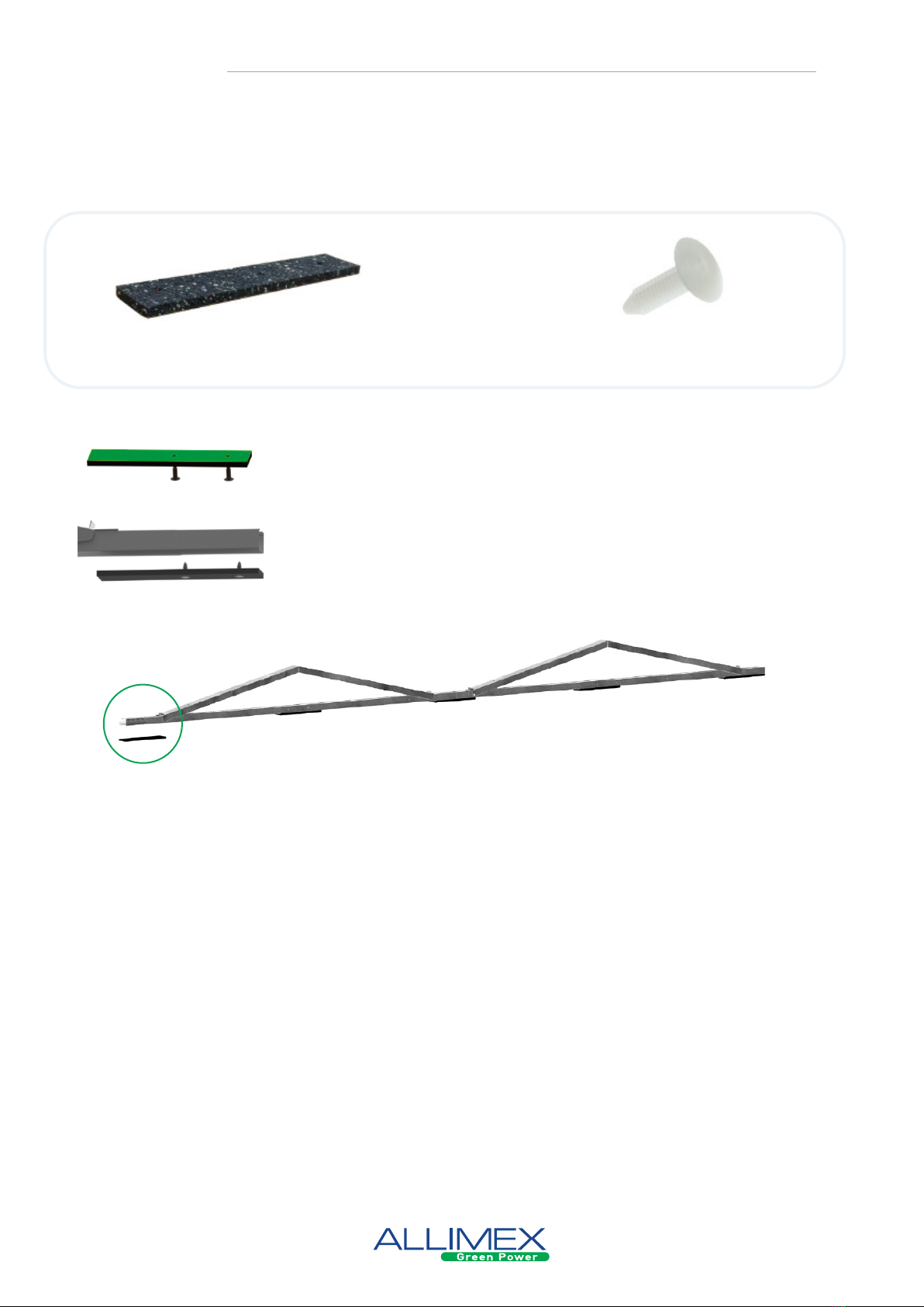
2. ATTACH END RUBBER AT THE END OF THE ROW
SolarSpeed end rubbers Plastic plugs
Skip this step if you use concrete or PP bases.
Push the plugs into the predrilled holes of the connectors.
Attach the connectors onto the rail, by pushing the plugs into the
pre-drilled holes.
INSTALLATION
5
Due to the continuous development of our products, a deviation on the image is possible. No rights can be derived from any printing or setting errors.
Dilatation (thermal interruptions)
In order to compensate for the thermal expansion of the SolarSpeed mounting frame, a new group
of panels must be started every 26 metres in the E-W direction. The distance between these 2 groups
of panels should be at least 300 mm, to ensure the use of ballast holders.
In the N-S direction, dilatation is ensured by sliding the rebate only 75% of the way into the rail of the
previous base unit every 30 metres, but not securing it with screws. This means that the rows are
still connected to each other (which benets the required ballast) and there is also room for thermal
expansion.
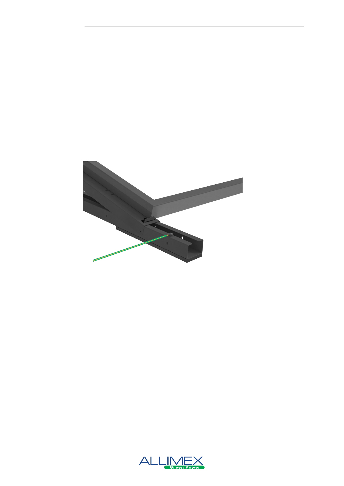
Align the rows according to the plan, considering the length of the panels.
Tip! To easily determine and keep the distance
between the base units, use and alignment tool.
Secure the length on the alignment
tool of the panel used.
Turn the alignment tool 180° and align
the rows.
3. ALIGN THE ROWS
SolarSpeed alignment tool Chalk line
Tip! Use a chalk line to set a horizontal and vertical mar-
king on the roof. When setting the markings, respect
the minimal edge zones (see general remarks).
INSTALLATION
6
Due to the continuous development of our products, a deviation on the image is possible. No rights can be derived from any printing or setting errors.
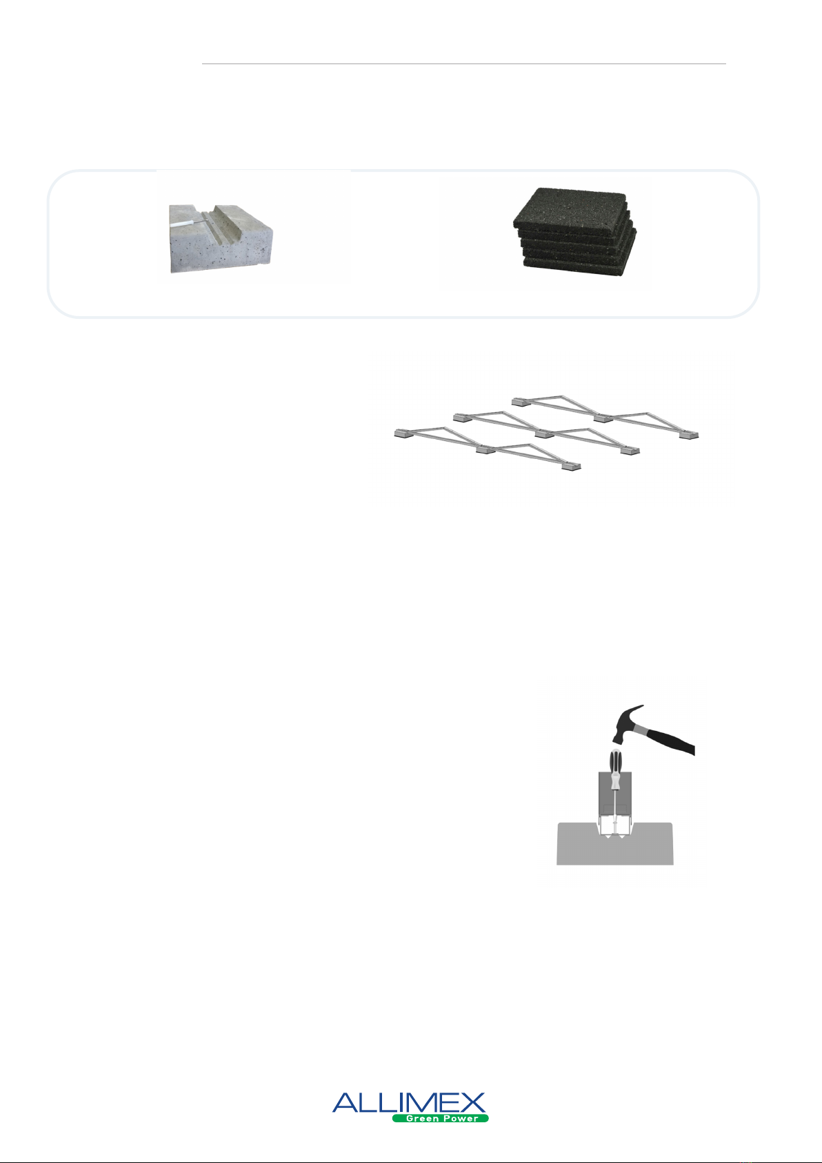
4. PLACEMENT CONCRETE BASE (optional)
Positioning concrete base
The Allimex concrete base is placed under
the full length of the connected base units.
This means that a base is placed at the end
and at the beginning of each connecter base
unit, as well as between the premounted
brackets. Rubber protection is placed
underneath each Allimex concrete foot to
protect the roof surface.
On a green roof or pebble roof you must remove the planting and/or pebbles where the concrete
bases should be placed.
ATTENTION! Concrete bases must be placed on all places as described above. In the absence of one
or multiple footings/bases, this could lead to serious stability problems.
Concrete base + impact anchor Protective rubber
Placement base-units
Once the Allimex concrete bases have been positioned correct-
ly, the connected base units can be placed on the bases and
attached. This attachment is done by SS rivets HPS-I 8/10x40.
This plug is punched into the provided holes with a hammer.
Next, the nail is screwed or punched into the plug. When pun-
ching the nail, it’s convenient to use a screwdriver so the Solar-
Speed base units won’t be damaged.
INSTALLATION

7
PP supports are placed under the entire length of the con-
nected base units. This means that there is a support at the
beginning and end of each of the connected basic units, as
well as in the middle of all mounting triangles.
The PP support can be attached to the base unit by faste-
ning it with sheet metal screws in the holes provided in the
rail of the base unit.
In principle, protective rubber is not necessary, as the PP
support is also compatible with PVC roofs. If the customer
still wishes to have an additional rubber protection under
the PP support, this can be attached to the underside of the
support with plastic plugs.
Due to the continuous development of our products, a deviation on the image is possible. No rights can be derived from any printing or setting errors.
5. PLACEMENT SOLAR PP-BASE (optional)
PP-base Plate screws
INSTALLATION
8
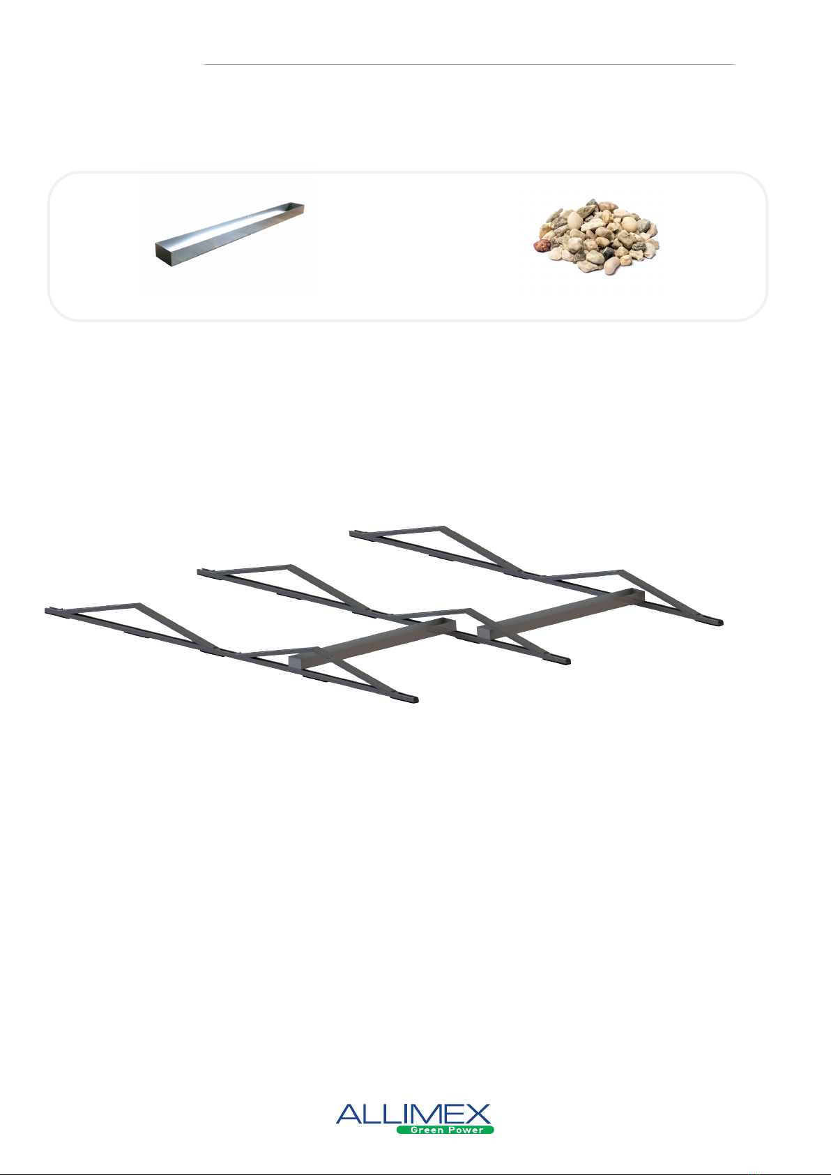
6. PLACEMENT BALLAST: L-PROFILES
Due to the continuous development of our products, a deviation on the image is possible. No rights can be derived from any printing or setting errors.
The ballast for an E-W set-up is placed on a set of
L-proles. This has the advantage of an extra con-
nection which makes the construction as a whole
even stronger.
ATTENTION! If possible, try to position the ballast
tiles as close to the base units as possible.
When installing on concrete bases, a higher central
support is provided to support the L-proles.
Set ballast L-proles
+ support
Plate screws Ballast tile
(provided by customer)
In arrangements where the system is placed on So-
lar PP supports, the central support should also be
placed on PP supports. An indication of the neces-
sary ballast, the placing and the way of ballasting
can be calculated with the free online software.
INSTALLATION
9
Due to the continuous development of our products, a deviation on the image is possible. No rights can be derived from any printing or setting errors.
Place the pebble stone bin underneath the base unit and ll the container with pebble stones. The
pebble stone bins have a standard size. If it is not possible to put these next to each other due to the
length of the panel, these could be placed alternately on the ground prole of the base unit.
ATTENTION! It’s forbidden to place gravel containers onto each other!
7. PLACEMENT BALLAST: PEBBLE STONE BINS
Pebble stone bin Pebble stones
INSTALLATION

10
8. INSTALLATION SOLAR PANELS
Due to the continuous development of our products, a deviation on the image is possible. No rights can be derived from any printing or setting errors.
Place the panels onto the mounting bracket and clamp them by using the appropriate end and mid-
dle clamps. The clamp instructions for the PV-modules must always be respected. Drawings are for
illustration purpose only.
ATTENTION! Tighten the Allen screws manually for the rst three revolutions before tightening them
with the electric screwdriver.
Clamps +
hexagonal socket screws
Solar panel
(provided by customer)
INSTALLATION
11
Due to the continuous development of our products, a deviation on the image is possible. No rights can be derived from any printing or setting errors.
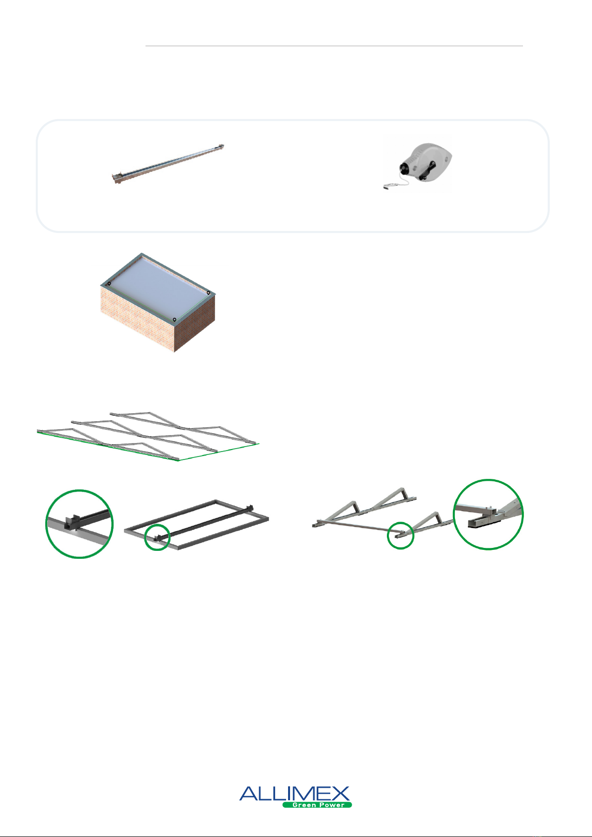
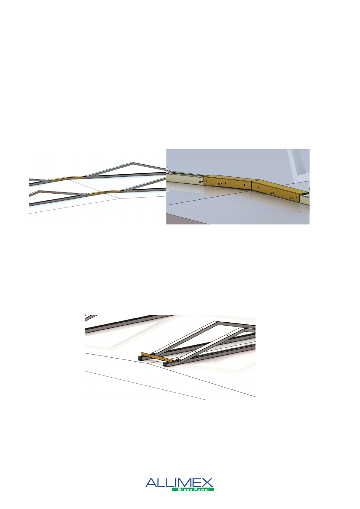
9. RIDGE CONNECTOR
For roofs with a slight pitch, we strongly recommend the use of ridge connectors. These pre-
vent the system from slipping.
Transverse ridge connections
With the transverse ridge connection, the transverse ridge prole is placed over the ends of the pro-
les. In the middle, the ridge prole can be folded to the appropriate angle. It is then fastened to the
base units with 8 self-tapping screws.
Longitudinal ridge connections
With the longitudinal ridge connection, the basic units are connected to each other by means of an L
prole. These are xed with at least two self-tapping screws to the top of both rails. For a roof pitch
of more than 2° it is also recommended to install L-proles over the full width (in East-West direction)
to prevent the structure from sinking unevenly.
INSTALLATION
12
Due to the continuous development of our products, a deviation on the image is possible. No rights can be derived from any printing or setting errors.
10. GROUNDING AND POTENTIAL EQUALIZATION
According to some standards e.g. NEN1010 (legislation is dierent in each country) metal frames
where solar panels are installed should be grounded. Because the rows are connected electrical and
mechanical by L-proles and gravel containers (step 6: “installing the ballast”), no further connections
have to be made between the dierent base units.
The separate elds have to be electrically conducted with each other via a ground wire. This connec-
tion can be made by clamping the isolation-free ends of the wire with a self-tapping screw on the
base units.
INSTALLATION

13
Due to the continuous development of our products, a deviation on the image is possible. No rights can be derived from any printing or setting errors.
11. CABLE MANAGEMENT (optional)
Cable tray supports
The cable tray support is attached to the rail by hooking the “Z” part of the support over the opening
of the rail. It is then xed to the rail with a plate screw.
Cable tray supports Plate screwCable tray
(not provided by Allimex)
Cable clips
The SolarSpeed cable clips make it possible to hang cables under the panel. The cable clips can be
pressed into the provided holes in the SolarSpeed triangle and oer space for cables up to Ø15mm.
INSTALLATION

14
Due to the continuous development of our products, a deviation on the image is possible. No rights can be derived from any printing or setting errors.
GENERAL REMARKS
The installer always has to check whether the rubber protection (provided underneath the basic unit) suces when instal-
ling onto a soft of half-soft underground. The installer also has to check the compatibility of the rubber protection with the
roof surface.
For the following installations, special instructions have to be kept in mind (these specic versions can be delivered on
demand):
• In an aggressive environment: all materials must be SS with the right specications to determine the aggressive sub-
stances.
• In sea salt environments: use anodized aluminium or SS.
Special attention to roofs with a pitch in E-W direction and to roofs that easily move up and down (e.g. as a result of vibrati-
ons from wind load or other causes):
• Without extra connections in N-S direction, the installation can tend to move downwards irregularly.
• In cases where you are dealing with roofs which have a negative and/or positive pitch, we recommend to make a con-
nection at the roof-ridge.
• For roofs with a pitch in N-S direction and which have a negative and a positive pitch, we recommend to make a
• connection at the roof-ridge.
• If in doubt, contact a specialized structural design agency.
Clamps:
• Only use clamps that the module manufacturers allow and/ or advise.
• Always clamp with the correct torque (max 9-11 Nm).
Special attention for installations on roofs in extreme circumstances:
• In the following situations/circumstances, the mounting frames of Allimex are not suitable unless there is a written
acknowledgement of Allimex (concerning a specic project):
* Roof height >20m
* Roof pitch PVC roofs >3°
* Roof pitch non-PVC roofs >4°
* Places where nearby buildings of other objects cause a wind-tunnel eect or increased wind speed
Contamination of the roof skin can lead to a lower friction coecient, which means that more ballast has to be provided or
(extra) mechanical connections have to be provided, to prevent sliding.
Edge zone:
The installer always needs to keep the minimal edge zone, which is described in de applying standards, free. An example of
such a standard is the NEN7250 but this standard is however not limitative.
Installers should always provide sucient ballast specic to individual installations. In case of doubt a specialized
ureau should always be consulted.
Always provide sucient East-West connections.
It is the responsibility of the installer to check whether the panels can be clamped in the way (on the short or long side,
position of the clamps, etc.) that is shown in this manual. If this is not the case, Allimex can in no way be held responsible
for any damage, in whatever form. Allimex can never be held liable if during installation materials are used that are not
supplied by Allimex.
The warranty conditions regarding the mounting frames of Allimex are available on demand. The installation manual should
be observed strictly, otherwise all guarantee agreements will lapse.
The installer is responsible for using the necessary personal protective equipment.
Allimex maintains the right to edit the installation manual at any time. It’s the responsibility of the installer to follow the
latest version, which is the only valid one. The latest installation manual is always available on demand.
REMARKS
Table of contents
Popular Solar Panel manuals by other brands


Solarsystems
Solarsystems SSA-21 installation instructions

Viessmann
Viessmann Vitosol 300-TM Installation information

ELERIX
ELERIX EXS-410MHC-B Technical manual

PowerWave
PowerWave M2-60 series installation manual

Akcome
Akcome SK6 Series manual

Projoy Electric
Projoy Electric PEFS-PL80S-11 installation guide