manuals.online logo
Brands
  1. Home
  2. •
  3. Brands
  4. •
  5. Westinghouse
  6. •
  7. Circuit Breaker
  8. •
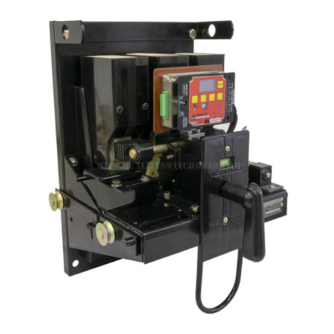
  9. Westinghouse DE-ION DH Series User manual

Westinghouse DE-ION DH Series User manual

This manual suits for next models

6

Other Westinghouse Circuit Breaker manuals

Westinghouse DB-75 User manual

Westinghouse

Westinghouse DB-75 User manual

Westinghouse DB-50 User manual

Westinghouse

Westinghouse DB-50 User manual

Westinghouse DB-75 User manual

Westinghouse

Westinghouse DB-75 User manual

Westinghouse VCP Series User manual

Westinghouse

Westinghouse VCP Series User manual

Westinghouse DB-50 User manual

Westinghouse

Westinghouse DB-50 User manual

Westinghouse De-ion DB-15 User manual

Westinghouse

Westinghouse De-ion DB-15 User manual

Westinghouse DH-P Series User manual

Westinghouse

Westinghouse DH-P Series User manual

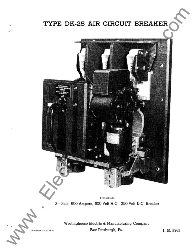
Westinghouse DK-25 User manual

Westinghouse

Westinghouse DK-25 User manual

Westinghouse De-ion DB-15 User manual

Westinghouse

Westinghouse De-ion DB-15 User manual

Westinghouse F-122 User manual

Westinghouse

Westinghouse F-122 User manual

Westinghouse De-ion 50-DH-350 User manual

Westinghouse

Westinghouse De-ion 50-DH-350 User manual

Westinghouse Porcel-line DHP Series User manual

Westinghouse

Westinghouse Porcel-line DHP Series User manual

Westinghouse De-opn User manual

Westinghouse

Westinghouse De-opn User manual

Westinghouse De-ion DM2R User manual

Westinghouse

Westinghouse De-ion DM2R User manual

Westinghouse AB DE-ION Series User manual

Westinghouse

Westinghouse AB DE-ION Series User manual

Westinghouse DS-206 User manual

Westinghouse

Westinghouse DS-206 User manual

Westinghouse DB-75 User manual

Westinghouse

Westinghouse DB-75 User manual

Westinghouse DB-50 User manual

Westinghouse

Westinghouse DB-50 User manual

Westinghouse F-11 User manual

Westinghouse

Westinghouse F-11 User manual

Westinghouse DBN-1016 User manual

Westinghouse

Westinghouse DBN-1016 User manual

Westinghouse DB-50 User manual

Westinghouse

Westinghouse DB-50 User manual

Westinghouse DB-75 User manual

Westinghouse

Westinghouse DB-75 User manual

Westinghouse De-ion DB-15 User manual

Westinghouse

Westinghouse De-ion DB-15 User manual

Westinghouse 50-DG-50 User manual

Westinghouse

Westinghouse 50-DG-50 User manual

Popular Circuit Breaker manuals by other brands

Siemens 3VT9524-4TG30 quick start guide

Siemens

Siemens 3VT9524-4TG30 quick start guide

Acrel ASCB1 Series Installation and operation manual

Acrel

Acrel ASCB1 Series Installation and operation manual

ABB SACE Emax 2 E2.2 manual

ABB

ABB SACE Emax 2 E2.2 manual

Eaton NOVA LBS 15 Installation and operation instructions

Eaton

Eaton NOVA LBS 15 Installation and operation instructions

ABB SACE Emax E1 quick start guide

ABB

ABB SACE Emax E1 quick start guide

Siemens SIRIUS 3RV1742 Original operating instructions

Siemens

Siemens SIRIUS 3RV1742 Original operating instructions

WEG FHU ACW125 installation instructions

WEG

WEG FHU ACW125 installation instructions

TERASAKI NHP TemBreak PRO P160 Series installation instructions

TERASAKI

TERASAKI NHP TemBreak PRO P160 Series installation instructions

Siemens Sentron 3VA9157-0PK1 Series operating instructions

Siemens

Siemens Sentron 3VA9157-0PK1 Series operating instructions

hager TS 303 User instruction

hager

hager TS 303 User instruction

ETI EFI-4B Instructions for mounting

ETI

ETI EFI-4B Instructions for mounting

Gladiator GCB150 Installation instruction

Gladiator

Gladiator GCB150 Installation instruction

nader NDM3EU-225 operating instructions

nader

nader NDM3EU-225 operating instructions

Eaton 50DHP-VR Instruction handbook

Eaton

Eaton 50DHP-VR Instruction handbook

ABB SACE Emax 2 E6.2 Instruction handbook

ABB

ABB SACE Emax 2 E6.2 Instruction handbook

Gewiss 90 RCD Installation

Gewiss

Gewiss 90 RCD Installation

OEZ LFN Instructions for use

OEZ

OEZ LFN Instructions for use

Eaton Power Defense PDG2 Instruction leaflet

Eaton

Eaton Power Defense PDG2 Instruction leaflet

manuals.online logo
manuals.online logoBrands
  • About & Mission
  • Contact us
  • Privacy Policy
  • Terms and Conditions

Copyright 2025 Manuals.Online. All Rights Reserved.

aiiaxiwiauwnwpiiitr
«
iaMiiiinyM
:
ujii
«
1
«
ii
'
*
(
i
.
«
i
»
«
:
a
.
M
«
i
)
r
«
Hu
#
!
i
»
iMLU
»
.
ai
*
w
<
»
ai
;
»
!
«
sl
SI
‘
81
1
»
«
w
»
*
m
*
B
/
J
o
tf
!
;
?
o
:
11
s
a
^
u
o
i
.
]
B
J
o
c
!
J
o
[
3
o
i
J
3
o
a
|
g
a
s
n
\
/
iuiiiiviy
.
'
a
.
wiiiif
«
wa
!
ru
.
5
niin
'
*
imjw
;
owB
,
xrKimf
»
y
<
£
'
»
HJmviiiuiiJi
.
BvjAi
6
»
a
«
II
II
ttCCUX
!
)
«
iuij
|
.
ur
/
i
«
»
iiu
»
(
Mwiiii
»
t
!
ii
*
)
»
iwi
«
fl
!
»
iuitt
«
wc
4
i
(
r
»
eni
’
aan
.
»
)(
Sf
»
nMivir
«
yfii
«
4
tllt
)
ieM
:
lntMr
/
'
.
uiwt
.
v
’
jJMBiim
.
m
'
tffc
'
tuiKniwdftimjiUiaiiuWffWWTM
'
ftysKm
^
u
«
i
^
«
HK
4
»
tWS
0
W
Courtesy of NationalSwitchgear.com
fl
.
B
.
32
-
150
-
.
3
A
RECEIVING
OPERATION
MAINTENANCE
MR
CIRCUIT
BREAKER
Type
BE
.
Horizontal
Drawout
Indoor
and
Outdoor
Service
INTERRUPTING
RATINGS
—
AMPERES
VOLTAGE
RATINGS
3
-
PHASE
INTER
-
RUPTING
RATING
MR
AMPERES
CQNTIN
'
CIRCUIT
BREAKER
Mill
.
KV
.
for
Rated
IJOIJS
MAX
.
At
TYPE
til
)
CYCLES
Rato
if
Mn
.
MV
A
.
Design
Rated
KV
.
INI
.
Amperes
KV
.
Voltage
MVA
.
50
-
DH
-
130
-
D
50
-
DIM
50
.
D
50
-
DH
4
I
30
-
D
ISO
4.76
3.6
-
600
4.16
21
,
000
21
,
000
21
,
000
36
,
000
36
,
000
20
,
000
20
,
000
40
,
000
40
,
000
6
,
300
6
,
300
10
,
600
10
,
600
21
,
000
21
,
000
26
,
000
25
,
000
25
,
000
37
,
500
37
,
500
32
,
000
32
,
000
44
,
000
44
,
000
13
,
000
13
,
000
22
,
000
2.2
,
000
23
,
000
2
:
3
,
000
150
4.16
4.76
3
,
5
‘
1200
150
4.16
4.76
3.5
2000
80
-
DHW
350
.
D
60
-
DH
'
'
250
'
D
250
4.16
4.16
4.76
3.85
1200
230
4.76
3.85
2000
75
-
DH
-
230
-
A
75
-
DH
-
250
-
A
250
4.6
7.2
.
8.25
'
0.23
1200
250
7.2
4.6
2000
75
*
DH
500
“
A
75
-
DH
-
50
Q
-
A
800
7.2
8
,
23
6.6
1200
500
6.6
7.2
8.25
2000
1
S
0
-
DH
-
130
-
A
ISO
-
DIM
50
-
A
150
13.8
13.0
6.6
600
150
13.8
15.0
6.6
1200
I
BO
-
DIM
!
50
-
A
1
B
0
-
DTI
-
250
-
A
250
13
,
8
18.0
6.6
1200
250
13.8
13.0
6.6
2000
IBO
-
DH
-
SOO
-
A
150
-
DH
-
B
00
-
A
300
13.8
18.0
11.5
1200
500
13.8
11.5
15.0
2000
WESTING
HOUSE
ELECTRIC
CORPORATION
SWIITCHGEAR
DIVBSII
0
N
EAST
PITTSBURGH
PLANT
SUPERSEDES
I
.
B
.
32
-
1
BO
-
3
EAST
PITTSBURGH
,
PA
.
MAY
,
19.03
(
H
®
p
.
10
*
59
)
©
Pxiwknd
in
U
.
8
-
A
.
Courtesy of NationalSwitchgear.com
sBi
*
u
,
'
diajnuaiii
*
jnMi
'
uWi
«
rii
!
i
.
lJMt
.
>
wmsia
,
>
MiWiirrt
«
i
»
iu
'
1
When
communicating
with
Westinghouse
regarding
the
product
covered
by
this
Instruction
Book
,
include
all
data
contained
on
the
nameplate
attached
to
the
equipment
.
*
Also
,
to
.
facilitate
replies
when
particular
information
is
desired
,
be
sure
to
state
fully
and
clearly
the
problem
and
attendant
conditions
.
Address
all
communications
to
the
nearest
.
Weslirighouse
-
representative
'
as
listed
in
the
back
of
this
book
.
i
*
mm
G
4
Ik
.
*
mm
rwtlwl
!
i
>
J
si
n
t
t
.
-
—
a
0
E
-
I
0
H
AIR
CIRCUIT
BREAKER
»
*
(
!
«
»
*
n
u
-
M
»
u
J
IK
I
-
-
DATE
OF
MAHlirACTUUE
R
.
STYLE
on
$
0
|
*
•
*
*
**
/
*
VJJb
*
*
A
>
\
4
Vi
«
IllXiX
.
rixrjt
*
:
M
«
'
K
*
*
f
'
»
*
rJltr
-
•
fc
INJ
'
.
ua
VI
*
*
»
i
||
*
>
J
,
iui
BREAKER
UNIT
l
COOK
SERIAL
*
M
£
JUV
»
M
.
V
*
**
*
l
»
HV
/
M
ft
\
i
uir
.
j
Otl
*
x
<
ib
.
i
»»
ip
(
•
Stf
>
ii
rt
wu
.
V
'
iaiBi
RATER
i
(
V
WILL
Fit
HOUSING
on
HE
Ml
»
«
*
»««
W
.
ei
.
au
'
uii
<
«
*
wp
*
^
iM
-
niiaj
'
'
'
M
H
<
I
«
U
.
iM
-
'
s
'
m
.
n
IC
.
I
.
MJAU
.
t
nW
^
c
.
iV
’
.
l
fvik
«
J
*
•
l
»
Hi
rA
'
Jj
fOiu
\
u
'
mnwj
n
xiiM
'
Aitaiii
Atutuui
Mcyuniy
-
irmtM
AlivcftMi
vi
7
.
i
n
uutt
&
zi
TYPE
MECHANISM
/
I
'
l
.
im
1
iijtvtinuwiti
IT
.
UMJHI
*
.
I
:
|
.
uxff
(
a
tijin
.
iiffi
'
UixrtrlfH
^
MAX
DESIGN
K V
**
*
+
>
»
III
'
J
«
!
!
••
>
•
MSV
%
WIHV
*
:
V
'
.
*
X
*
dAf
.
AMPERES
CLOSING
VOLTAGE
.
loJiiiit
.
f
'
.
ivi
i
ii
«
K
J
»
i
«
y
.
i
>
ix
li
.
'
c
ik
MU
J
ik
*
i
*
>
»
A
»
l
«
«
V
'
llhl
^
l
llVI
'
.
AJ
l
.
v
%
.
i
TRIPPING
VOLTAGE
CYCLES
•
i
uiij
I
-
,
J
.
I
H
'
V
VlU
'
l
>
iiuitiuJJN
-
>
i
Uig
(
lViU
-
l
M
(
<
ki
«
#
.
'
1
«
*
>
-
<
«
«
tqv
|
Vi
/
4
lfert
.
)
fea
ft
*
K
‘
>
IJ
.
kM
.
i
1
.
cokii
'
AlvwuV
l
.
*
i
*
MsfvMjB
tUAlz
.
xm
/
.
i
S
/
M
1
H
u
*
«
V
<
4
-
.
kVr
.
sr
*
,
-
2
U
7
ID
9
»
27898
«
220
MO
22001
221798
$
217701
j
WESTING
HOUSE
ELECTRIC
CORF
.
MADE
01
tl
.
S
.
A
.
PATENTS
i
!
«
•
*
NP
6
m
«
-
C
*
For
a
permanent
;
record
,
it
is
suggested
that
all
nameplate
data
be
duplicated
and
retained
in
a
convenient
location
.
•
\
;
;
Courtesy of NationalSwitchgear.com
vr
-
>
rt
-
l
‘
"
-
I
-
^
'
u
^
'
1
.
^
-
1
V
*
•
-
'
'
’
:
V
.
v
-
>
V
'
v
•
"
>
V
"
atisjlrt
-
81
s
»
r
MS
§
SsM
*
i
@
Sfe
:
S
«
L
&
B
*
:
!
:
-
B
;
-
r
'
*
.
.
-
nM
Wl
,
-
L
•
•
•
.
V
-
"
nrv
/
.
-
;
;
&
$
"
.
.
AL
’
,
i
.
-
;
v
'
.
!
ri
-
^
dpl
!
v
;
;
g
,
:
;
:
#
§
:
:
:
1
ss
.
•
-
•
-
•
‘
.
-
:
(
''
••
J
V I
:
m
<
:
.
.
!
;
$
.
V
.
:
4
;
i
)
V
-
.
•
•
?
-
;
r
:
:
#
.
r
\
y
.
,
'
-
'
!
:
.
:
fill
*
«
111
«
|
Sppfr
.
SSiSittSS
*
®
*
!
SSliggr
*
liilife
igplttL
tifeRy
-
1
'
r
.
T
'
r
i
,
.•
K
&
rsrLLLLrq
•
.
•
jfSSPH
!
gLLfqL
|
;
.
;
L
:
Lp
fesiS
;
-
!
j
9
K
|
9
HHa
|
HH
^
pr
-
fcttpQPllwi
PiliM
SSL
®
SLLLL
:
.
us
.
m
&
aur
’
•
v
5
-
.
&
:
:
V
'
.
-
i
*
1
.
"
Sltll
«
W
®
®
;
’
L
,
-
:
-
a
•
•
:
;
'
:
y
:
•
;
•
:
i
:
*
<
?
:
•
I
r
?
:
:
•
^
ma
*
•
'
iT
-
=
T
•
fa
-
..
-
.
>
SB
:
!
•
ILL
f
.
r
.
V
<
*
"
•
>
.
•
L
3
P
#
f
.
:
‘
TSS
:
B
;
v
V
.
:
;
-
I
.
;
.
,
*
.
.
:
:
.
;
v
|
S
;
'
.
-
®
,
r
,
'
yv
:
[
.
M
.
'
i
<
:
w
.
i
"
*
7
\
.
:
Vr
?
i
i
m
m
Gins
oi
:
the
outstanding
improvements
in
modern
power
distribution
lias
been
the
development
of
the
air
cirpii
.
it
breaker
by
Westinghouae
for
distribution
circuit
voltages
.
On
circuits
where
the
duty
on
breakers
is
heavy
,
long
life
with
:
a
minimum
of
.
maintenance
makes
the
De
-
ion
air
breaker
an
outstanding
performer
.
In
the
type
DH
magnetic
De
-
ion
air
circuit
breakers
,
Westing
-
house
offers
a
complete
standard
line
for
circuits
from
2.3
to
IB
kv
.
Each
of
the
type
DH
air
circuit
breakers
is
three
-
pole
,
electrically
operated
,
and
is
built
as
a
complete
horizontal
drawoul
:
unit
for
metal
-
clad
switchgear
.
Breaker
units
of
the
same
rating
;
are
interchangeable
so
that
changing
breakers
is
a
.
.
matter
of
minutes
.
Since
they
are
drawn
out
horizontally
,
no
lowering
or
lifting
is
necessary
.
Steel
barriers
and
automatic
interlocks
prevent
contact
with
live
parts
while
the
breakers
are
being
changed
.
.
As
in
the
case
of
most
highf
voltage
electrical
equipment
,
these
breakers
should
be
inspected
and
maintained
at
regular
intervals
in
order
to
obtain
the
•
most
dependable
performance
.
(
£
»
!
>
Courtesy of NationalSwitchgear.com
I
'
B
,
.
32
-
150
-
3
A
AIR
CIRCUIT
IBREARKR
M
1
m
i
'
i
;
!
PSJ
A
barrier
assembly
is
-
placed
oi
>
.
the
breaker
before
it
is
rolled
into
its
cell
.
The
front
.
sheet
is
of
one
-
eighth
high
steel
to
form
a
grounded
barrier
between
personnel
and
live
parts
when
the
unit
is
in
the
cell
.
On
15
lev
breakers
this
barrier
assembly
is
in
two
parts
for
convenience
in
handling
.
The
type
DH
air
circuit
breaker
is
a
three
-
pole
,
electrically
operated
,
horizontal
drawout
unit
for
metal
-
clad
switchgear
.
In
.
the
type
designation
,
the
numbers
preceding
DH
indicate
the
voltage
rating
in
hundreds
of
volte
,
and
the
numbers
follow
-
ing
DH
indicate
tire
maximum
irxterruptmg
.
rating
in
thousands
of
leva
.
The
various
ratings
have
similar
structural
features
and
many
parts
in
common
.
Fig
,
1
shows
a
type
-
.
15
O
-
DH
-
250
A
breaker
with
the
main
,
barrier
assembly
and
one
arc
chute
re
-
moved
.
This
shows
clearly
the
arrangement
of
the
arc
chutes
and
blowout
magnet
assemblies
,
,
the
con
-
tacts
and
insulated
operating
rods
,
and
the
solenoid
operating
mechanism
.
These
components
are
sup
-
ported
in
a
welded
steel
frame
mounted
on
flanged
wheels
for
guiding
it
into
the
metal
-
clad
cell
.
.
In
the
lower
part
of
the
frame
also
is
located
the
levering
-
in
.
device
for
moving
the
breaker
into
final
contact
engagement
.
This
device
is
interlocked
with
the
.
mechanism
to
prevent
inserting
or
withdrawing
the
breaker
with
the
contacts
closed
.
Also
located
in
the
lower
part
of
the
frame
are
the
secondary
con
-
,
tacts
for
automatically
‘
disconnecting
the
control
wiring
when
the
breaker
is
withdrawn
,
the
auxiliary
•
switch
,
and
other
auxiliary
devices
.
.
'
5
-
>
'
vjk
..
t
A
'
:
r
\
-
-
f
-
f
;
hn
#
v
.
,
^
.
;
VAftC
CHUTE
.
.
••
•
••
•
•
i
-
•
>
\
•
•
:
1
-
V
;
-
V
"
?
r
*
MMNR
:
"
rv
-
!
.
.
.
.
.
.
'
••
i
"
/
.
-
:
-
IStftTjg
!
f
'
Ol
.
pf
»
iP
.
GKS
^
rrp
‘
-
-
r
-
;
L
!
INTER
POLE
•
*
OARRIER
ASSEMBLY
:
S
i
•
.
BSaa
^
i
:
«
iSI
l
|
|
.
.
.
<
<
i
i
.
51
.
‘
ARC
HORN
;
CONNECTOR
;
3
»
%
m
atiurTf
.
n
.
;
.
.
.
^
A
,
.
v
^
OPERATING
MOO
l
-
il
1
'
i
.
;
y
-
;
'
*
fe
:
y
‘
\
h
:
JUiu
-
'
t
-
z
.
v
"
i
*
M
4
iV
-
:
-
.
i
-
’
I
-
.
.
.
I
’
.
;
,
.
.
,
:
l
**
.
fefii
t
ING
I
-
*
'
\
*
.
t
:
:
.
*
••
FIG
.
L
Typo
1
B
0
-
DH
-
280
A
Circuit
Breakar
with
Half
of
Main
Barrier
and
One
Arc
Chute
Removed
/
•
All
type
DH
breakers
are
assembled
and
given
operating
tests
at
the
factory
,
after
which
they
are
carefully
inspected
and
prepared
for
shipment
by
workmen
experienced
in
.
the
proper
handling
and
packing
of
.
electrical
equipment
.
In
order
to
afford
maxim
um
protection
against
damage
,
the
main
bur
-
ner
assembly
and
the
arc
chutes
are
packed
sep
-
arately
.
For
each
,
three
-
pole
breaker
there
is
one
barrier
assembly
and
three
arc
chutes
.
After
the
equipment
has
been
unpacked
,
make
'
careful
-
inspection
for
any
damage
which
may
have
c
curved
in
transit
If
the
apparatus
has
been
damaged
,
file
a
claim
immediately
with
the
carrier
and
notify
the
nearest
Westing
house
Sales
office
,
HANDinro
.
Remove
the
crating
and
packing
carefully
to
•
avoid
damage
from
negligent
handling
of
crowbars
or
other
tools
.
Use
a
nail
puller
for
the
uncrating
.
.
Care
must
be
used
in
handling
the
arc
chutes
,
,
since
the
splitter
plates
within
them
are
made
of
a
ceramic
material
which
may
break
if
dropped
.
The
base
of
the
crate
may
be
used
as
a
skid
for
moving
the
breaker
,
or
the
breaker
may
be
lifted
3
Courtesy of NationalSwitchgear.com
RECEIVING
,
HANDLING
AN
®
STORING
t
/
W
MT
'
KOmtilunvMMUaa
.
t
'
.
wAilisXliasCOKlA
'
.
i
’
.
l
’
)
-
.
X
*
-
41
'
m
*
*
e
-
X
~
'
•
l
-
*
*
"
«
fr
"
'
"
*
1
>
HSKM
*
/
(
i
,
urwuvIJ
.
I
.
!
.
•
-
«
J
w
;
,
.
„
wrl
1
„
with
slings
under
the
orate
.
II
the
breaker
is
to
be
Jilted
with
slings
,
move
it
while
it
is
still
crated
.
Alter
the
breaker
is
unpacked
,
the
best
way
to
move
it
is
by
rolling
it
on
its
own
wheels
,
;
H
it
is
necessary
to
lift
the
breaker
after
if
is
tmcrated
,
lilt
it
without
the
arc
chutes
or
;
barriers
in
,
place
.
Slings
may
be
placed
under
the
!
breaker
frame
.
or
in
holes
provided
in
the
frame
.
!
Use
a
spreader
to
prevent
th
©
cables
from
distorting
the
blowout
magnets
.
STORING
The
arcing
chambers
are
shipped
in
separate
containers
to
guard
against
damage
from
rough
handling
and
for
better
protection
,
from
dust
and
water
or
liquids
,
containers
until
ready
for
us
©
.
Store
all
components
of
these
breakers
in
a
clean
dry
place
..
During
the
storage
period
,
keep
them
sufficiently
warm
to
prevent
'
moisture
condensation
.
Store
them
in
their
shipping
TABLE
©
IP
APPROXIMATE
*
WEIGHTS
(
1
m
Fm
.
radte
)
•
W
'
l
IRMtflu
>
|
i
f
.
»
i
WH
*
4
>
V
1
N
1
»
NIMto
>
l
*
MWti
»
*
4
%
&
*
«
«
>
*
**
uAuvMlxt
'
.
ViKj
i
,
«
,
*
_
*
>
.
;
*
*
»
MU
»
nnrii
»
)
<
=
-
•
»
J
1
l
\
t
-
/
J
>
.
'
On
<
'
h
;
4
t
/
i
.
i
BREAKER
WITHOUT
CHUTE
ft
BARRIER
>
BREAKER
*
SINGIE
m
CHUTE
AMPERE
RATING
BARRIER
ASSEMBLY
COMPLETE
BREAKER
TYPE
80
-
DH
*
150
-
1
)
S
0
-
DH
-
1
S
0
-
D
600
-
1200
2000
676
45
75
1065
1050
45
95
1.260
'
80
-
DH
-
2304
)
50
-
DH
-
250
-
D
1200
875
•
1050
45
75
1085
1280
2000
45
95
1400
75
-
DH
-
250
-
A
75
-
DH
-
500
1200
-
2000
1200
-
2000
•
65
160
1750
2075
1600
105
160
150
-
PH
-
150
-
A
160
«
DH
-
250
-
A
.
150
-
DH
-
250
A
150
-
DH
-
500
-
A
150
-
DH
-
50
Q
-
A
600
-
1200
1200
2000
'
1200
2000
1250
70
'
160
1620
1250
70
160
1620
1770
1928
2075
1400
70
160
1450
105
160
105
1600
160
iMjaattmiwaisiraiwiaitiiiiiafisiBsii
ttvwwnii
Bjouui
.
'
aeww
w
,
i
>
luiMittiMSmvuuiwmtui
^
iausMitfswmJhfctirUMi
^
w
.
UiHtfjiiv
/
.
uiimfcnsiWWiWMMsnaHaiiii
I
*
M
;
«
PH
#
M
«
H
J
;
JMI
IUKI
M
a
*
.
n
sviiiiuiMitm
:
'
*
]
Mummenunai
uu
iMit
*
un
»
tin
iLiflowM
'
iSi
.
'
KiJUiKifeitfxo
i
^
tnui
itursw
*
AIM
*
,
INSTALLATION
With
the
exception
of
the
arcing
chambers
and
barriers
,
these
breakers
are
shipped
completely
{
assembled
and
adjusted
.
No
adjustments
should
be
required
and
none
should
be
made
unless
obviously
needed
.
!
i
When
the
breaker
has
been
removed
from
the
crate
,
remove
braces
which
support
the
blowout
magnet
pole
pieces
during
shipment
,
CmiMmw
Severe
injury
may
be
sustained
if
any
part
of
the
body
is
struck
by
the
con
-
tact
arms
since
they
move
very
rapidly
on
the
opening
stroke
.
Personnel
working
about
the
breaker
should
stay
clear
o
£
the
£
rpaco
in
which
the
contact
arms
move
while
breaker
is
closed
or
is
being
closed
,
.
If
breaker
has
been
closed
by
hand
,
always
remove
hand
closing
lever
before
trippixig
.
The
following
sequence
of
operations
should
be
performed
in
preparing
the
breaker
for
use
:
3
L
Breakers
are
usually
shipped
with
the
con
-
tacts
closed
and
with
a
tie
on
the
trip
lover
to
'
pre
*
grease
.
vent
tripping
.
Alter
the
breaker
is
unpacked
and
the
shipping
lies
and
braces
removed
,
lake
off
the
tie
on
the
trip
lever
and
trip
the
breaker
.
Then
close
the
breaker
carefully
by
hand
,
using
the
removable
hand
closing
lever
.
Make
certain
ilial
all
parts
are
functioning
properly
and
,
that
there
hi
no
binding
or
excessive
friction
.
As
the
contacts
touch
near
the
end
of
the
closing
stroke
,
the
force
necessary
to
close
the
breaker
increases
rapidly
.
2
>
n
With
the
breaker
hi
the
closed
,
position
,
check
the
contacts
to
make
certain
that
the
adjust
-
ments
have
not
been
disturbed
.
Iter
proper
settings
,
refer
to
the
section
of
Fig
.
6
which
matches
the
contact
,
design
of
the
breaker
being
'
installed
,
adjustments
are
required
,
they
may
be
made
as
described
on
page
9
.
,
K
A
light
film
of
grease
hi
applied
,
to
both
the
arcing
and
main
contacts
before
the
breaker
is
operated
at
the
factory
.
This
film
is
normally
removed
before
shipment
.
Before
the
breaker
is
placed
in
service
,
inspect
all
contacts
fence
.
that
they
are
free
oi
oil
or
l
Courtesy of NationalSwitchgear.com
UB
.
.
32
-
150
-
3
A
mSTALJLATION
AIR
CIRCUIT
BREAKER
3
*
The
breaker
is
more
easily
handled
with
the
arc
chutes
and
barriers
removed
;
'
mount
these
parts
alter
the
breaker
has
been
moved
near
the
melal
-
gia
d
c
ell
strue
l
:
ure
,
Before
installing
the
arc
chutes
,
play
a
stream
of
dry
compressed
air
through
them
from
each
,
end
to
remove
any
dust
,
or
.
foreign
matter
.
Then
examine
the
chutes
to
make
certain
that
the
vents
and
slots
are
open
and
free
from
foreign
material
.
Assemble
the
arc
chutes
on
the
breaker
by
removing
the
re
-
taining
straps
from
the
froxit
of
the
magnet
pole
pieces
and
sliding
the
chutes
into
position
,
making
sure
that
the
rear
arcing
horn
connectors
properly
engage
the
contacts
on
the
blowout
coils
.
After
a
chute
has
been
placed
in
'
position
,
make
sure
(
1
)
that
it
is
centrally
located
so
that
there
is
no
interference
with
the
travel
of
the
moving
con
-
tacts
and
(
2
)
that
it
is
securely
held
in
position
by
the
retaining
strap
with
top
of
the
chute
parallel
to
the
top
of
the
laminated
,
pole
faces
.
Connect
the
shunt
strap
to
the
front
arcing
horn
in
the
chute
.
Tighten
the
lower
connection
of
the
-
shunt
strap
since
:
it
may
have
loosened
during
transit
.
The
are
chute
is
now
completely
installed
.
Make
a
final
check
by
operating
the
breaker
slowly
by
hand
to
me
that
there
is
no
interference
in
the
movement
of
the
moving
contact
C
The
interpole
barrier
assembly
should
now
be
put
in
place
.
The
6
kv
breakers
have
a
one
piece
assembly
.
Blowout
magnet
mi
carta
channels
have
their
front
edges
beveled
to
help
guide
barrier
plates
into
place
.
.
The
lower
rear
comer
of
:
the
outside
mi
carta
plate
goes
inside
the
steel
gusset
of
the
frame
.
The
front
steel
sheet
of
the
barrier
assembly
is
'
centered
on
the
breaker
by
a
notch
on
the
bottom
edge
at
the
middle
,
which
should
engage
a
locating
pin
on
front
edge
of
breaker
frame
.
Two
bolts
at
lower
front
comers
hold
,
assembly
in
place
.
Because
of
size
and
weight
the
interpole
barrier
assembly
on
the
1
!
3
kv
breakers
is
divided
in
two
parts
.
Righ
t
half
goes
on
first
.
The
front
sleei
sheets
are
aligned
by
two
locating
pins
'
at
lower
front
•
•
corners
and
single
bolt
at
top
center
.
Two
bolts
at
lower
front
corners
hold
assembly
in
place
,
.
!
>
»
The
breaker
is
now
ready
to
bo
operated
electrically
.
Each
breaker
should
be
closed
and
tripped
electrically
several
times
before
being
con
-
nected
to
high
voltage
.
Those
operations
may
be
made
at
the
test
position
in
the
cell
or
by
means
of
.
other
test
facilities
provided
.
See
page
12
of
this
instruction
book
and
LB
.
32
-
150
*
4
,
page
33
,
for
information
concerning
placing
tlie
breaker
in
the
cell
.
The
hand
closing
lever
must
always
he
re
-
ft
m
Cv
i
in
I
#
mi
$
=
:
*
,
m
•
i
•
:
'
*
•
t
V
'
X
V
ft
/
J
?
)
j
frtJi
=
v
;
:
.
l
*
&
:
l
s
j
L
>
M
r
M
i
m
.
SIS
1
B
t
m
fmm
-
mamm
5
'
i
#
:
•
:
M
LigL
,
jsam
pa
?
.•
mi
iH
5
m
at
kfc
w
.
'
>
:
•
u
.
\
:
>
m
.
!
m
m
mm
5
iV
H
»
fi
'
'
-
V
,
:
.
_
•
»
-
•
*
'
A
?
-
1
—
FIO
.
2
,
Typical
Contact
Assembly
Shown
in
Closed
and
Latched
Position
moved
from
socket
in
mechanism
before
making
*
electrical
operation
.
If
electrical
operation
is
quick
and
positive
on
both
close
and
open
,
breaker
is
now
ready
to
be
levered
into
operating
position
.
'
•
Cat
&
ttoxi
:
Do
not
attempt
to
close
by
hand
,
against
axr
energized
circuit
,
any
breakers
covered
by
this
,
instruction
book
,
,
To
insure
sufficient
closing
force
and
speed
,
4
these
breakers
should
bo
closed
electrically
from
an
adequate
power
source
.
See
NEMA
Standard
SO
6
-
213
.
I
*
When
this
drawout
equipment
is
put
into
,
the
cell
and
moved
in
beyond
the
tost
position
,
the
high
voltage
parts
of
the
breaker
will
be
energized
*
If
the
barrier
is
completely
as
-
sembled
on
!
the
breaker
,
personnel
will
be
protected
from
contact
with
the
live
parts
.
If
,
however
,
the
barrier
assembly
is
left
off
and
the
breaker
rolled
into
the
cell
,
live
parts
exposed
.
The
breaker
should
never
bo
rolled
into
an
energized
cell
structure
beyond
the
test
position
without
having
the
complete
barrier
assembly
in
place
.
are
£
Courtesy of NationalSwitchgear.com
Before
adjusting
.
a
circuit
breaker
,
ii
.
is
advan
-
tageous
to
become
familiar
with
the
construction
and
function
of
the
various
parts
.
The
following
paragraphs
describe
the
operation
and
the
various
adjustments
which
can
be
made
.
This
material
should
be
studied
carefully
before
doing
any
work
on
the
breaker
.
The
general
arrangement
of
the
breaker
com
-
ponents
is
shown
in
Fig
.
1
.
The
solenoid
coil
is
built
to
exert
a
horizontal
force
on
the
mechanically
-
•
trip
-
free
linkage
.
This
linkage
,
in
turn
,
exerts
an
upward
force
on
the
pole
unit
insulating
operating
rods
.
The
moving
contact
arms
carry
the
main
,
intermediate
,
and
arcing
contacts
.
On
ripening
,
these
contacts
separate
in
the
order
named
;
on
closing
,
they
touch
in
the
reverse
order
.
£
On
the
outer
ends
of
the
condenser
bushings
are
clusters
of
finger
contacts
for
engaging
the
main
circuit
contacts
in
.
the
cell
.
Above
the
arcing
con
-
tacts
are
located
the
blowout
magnets
and
arc
chutes
.
The
breaker
is
tripped
by
lifting
the
trip
-
ping
trigger
either
manually
,
or
electrically
by
means
of
the
trip
coil
.
link
,
the
major
linkage
collapses
under
the
force
of
the
contact
springs
and
the
accelerating
springs
which
are
located
in
an
air
bumper
attached
to
the
trip
free
lever
,
The
junction
of
the
upper
and
lower
trip
free
.
links
moves
to
the
right
-
and
the
trip
free
lever
rotates
clockwise
,
thus
opening
the
breaker
.
The
position
of
the
linkage
is
then
that
shown
in
.
Figure
;
4
J
3
.
In
moving
to
this
position
the
roller
on
the
lower
trip
free
link
has
disengaged
lire
closing
latch
.
The
retrieving
'
springs
now
move
the
solenoid
core
which
moves
the
linkage
to
the
reset
position
shown
,
in
Figure
4
-
C
.
In
this
position
the
tripping
latch
is
reset
and
the
breaker
may
be
re
closed
.
as
MECHANISM
PANEL
The
mechanism
panel
is
mounted
on
the
front
of
the
closing
solenoid
,
mechanism
as
shown
,
in
Fig
,
3
.
On
it
:
are
mounted
,
the
following
auxiliary
devices
included
as
standard
on
all
breakers
:
$
Ipm
1
t
Trip
MaffpiieL
This
device
may
be
equipped
with
a
coil
lor
direct
curmet
or
-
alternat
-
ing
current
or
capacitor
tripping
.
OPERATING
-
MECHANISM
C
^
l
4
Mf
Swiiteliin
This
switch
causes
the
supply
to
the
closing
solenoid
to
be
cut
off
after
the
breaker
is
closed
.
Pwsiitikm
XMdteatoiv
This
device
gives
positive
'
indication
of
the
position
of
the
breaker
contacts
.
Offt
&
rafiaiii
-
Ctovmtev
*
This
counter
records
each
operation
,
of
the
breaker
.
The
solenoid
,
operating
mechanism
with
its
trip
-
free
linkage
is
shown
in
Fig
.
4
,
In
this
mechanism
the
horizontal
pull
of
the
solenoid
coil
is
transmitted
to
.
the
contact
,
operating
rods
through
.
a
system
of
links
which
rotates
counter
-
clockwise
about
the
operating
center
.
The
linkage
system
consists
of
four
major
links
:
th
©
non
-
trip
free
lever
,
trip
free
lever
,
upper
trip
free
link
,
and
lower
trip
free
link
.
These
members
are
arranged
as
shown
,
and
are
a
held
to
form
a
rigid
member
by
the
cam
link
and
tripping
cam
.
The
tripping
,
earn
is
held
,
fixed
by
the
tripping
latch
.
When
the
solenoid
is
energized
,
.
if
pulls
on
the
j
unction
of
the
non
-
trip
free
lever
and
the
lower
trip
free
link
,
causing
the
system
to
rotate
about
the
operating
center
.
The
trip
free
lever
theii
exerts
an
upward
force
on
the
operating
rods
through
the
cross
bar
to
close
the
breaker
.
The
breaker
!
is
held
.
in
this
position
by
the
closing
latch
and
the
tripping
latch
,
:
!
V
j
|
«
p
)
RAvyoufp
!
LATCH
CHECK
The
breaker
is
tripped
either
electrically
or
manu
-
ally
by
lifting
the
trigger
which
disengages
the
primary
latch
.
This
allows
the
tripping
latch
to
release
the
tripping
earn
so
that
it
.
.
is
free
to
rotate
.
Without
the
restraining
force
of
the
cam
and
cam
•
V
.
£
SWITCH
.
•
•
CUT
-
OFF
•
'
SHUNT
TRIP
SWITCH
•
:
MAGNET
-
*
.
.
w
•
u
.
FIG
.
3
.
Mechanism
Paruil
Courtesy of NationalSwitchgear.com
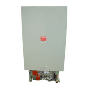
t
,
B
'
n
-
m
-
m
OPERATION
AM
®
ADJUSTMENT
AIR
CIRCUIT
BREAKER
i
»
*
i
*
•
>
>
•
«
«
1
INSULATED
1
OPERATING
ROD
,
TRIP
FREE
LEVER
,
CROSS
BAR
TRIPPING
LATCH
,
OPERATING
CENTER
UPPER
TRIP
FREE
LINK
PRIMARY
LATCH
-
STATIONARY
CORE
MOVABLE
CORE
;
r
,
/
[
RETRIEVING
C
-
OsJ
SPRINGS
TRIPPING
CAM
i
F
~
V
\
!
I
N
s
nra
-
.
stsx
.
z
_
r
0
HAND
CLOSE
LEVER
>
i
)
—
—
-
i
O
>
J
a
CAM
LINK
-
'
'
-
l
”
"
*
^
nET
^
]
'
jiffi
-
=
»
^
x
:
z
^
3
r
NON
-
TRIP
-
FREE
LEVER
SOLENOID
COIL
LOWER
TRIP
CLOSING
FREE
LINK
LINKS
CLOSING
LATCH
„
/
MAGNET
BACK
PLATE
CLOSING
LATCH
SPRING
A
CLOSED
POSITION
I
”
>
«
*
«
-
rr
—
i
•
Mwwn
*
A
t y
*
<
-
1
,
4
\
r
1
«
.
«
srr
-
*
>
WAII
r
-
*
-
jrMi
|
“
ua
«
xv
•
«
-
«
.
if
—
'
»
.
.
•
•
•
*
•
»
I
»
*
V
*
,
v
,
n
-
r
>
V
"
I
*
JN
^
v
.
«
'
~
\
S
\
i
te
V
r
-
V
^
JN
L
m
(
%
csr
-
—
X
,
\
c
OW
'
7
T
1
s
?
o
i
r
B
C
RESET
POSITION
TRIP
”
FREE
POSITION
.
•
«
M M
'
.
'
*
)
.
.
M n
*
*
'
r r
'
M i
«
411
U M
«
*
.
I
»
•
T
-
n
*
<
•
*
>
#
«
HiaMf
»
»
*
«
»
»
'
1
*
.
wsif
-
III
;
•
.
I
.
I
.
i
.
vI
.
ir
i
y
,
_
nrAi
FIG
*
<
L
Solenoid
Operating
Meohantam
The
foliowmg
special
devices
may
also
be
mounted
on
ihe
mechanism
panel
when
required
:
Underroltagre
Trip
MfcMfaMeisai
*
This
is
a
.
magnetically
held
device
*
which
when
released
will
trip
the
breaker
using
energy
stored
in
a
spring
during
the
mechanism
retrieving
'
motion
.
For
in
-
stantaneous
release
,
,
the
holding
magnet
coil
may
be
connected
to
d
-
c
with
a
series
resistor
to
suit
the
voltage
or
it
may
be
supplied
with
low
voltage
d
-
c
from
an
a
-
o
control
voltage
through
a
small
transformer
and
rectox
assembly
mounted
in
fixe
cell
structure
.
For
time
delayed
release
,
a
special
very
high
resistance
coil
is
used
in
the
holding
magnet
and
it
is
supplied
with
about
300
volts
d
-
c
from
a
transformer
,
rectox
,
and
;
capacitor
assembly
mounted
in
the
cell
.
The
capacitor
is
connected
across
the
coil
and
provides
a
slowly
decaying
holding
current
.
See
Descriptive
Data
sheet
33
-
131
.
The
holding
magnet
is
-
mounted
on
the
mechanism
.
panel
to
the
left
of
the
shunt
trip
magnet
.
U
7
JJ
Courtesy of NationalSwitchgear.com
OPERATION
AND
ADJUSTMENT
may
be
that
tripping
latch
roller
cannot
drop
into
cam
notch
.
Remove
front
half
of
horizontal
panel
forming
seat
of
.
the
chair
in
the
frame
.
1
This
gives
easy
access
to
the
gap
.
Using
hand
closing
lever
,
close
breaker
.
part
way
,
trip
,
and
than
slowly
'
re
-
trieve
moving
core
.
Note
whether
or
not
tripping
latch
roller
drops
into
cam
notch
.
U
If
necessary
to
increase
clearance
to
get
inch
minimum
,
remove
front
panel
as
follows
.
Remove
spring
from
•
operating
arm
of
counter
,
four
bolts
and
then
turn
panel
as
though
hinged
at
left
edge
to
prevent
damage
to
wiring
,
‘
Set
out
of
way
as
shown
on
Fig
.
5
.
There
is
no
need
to
remove
wiring
.
The
non
trip
free
lever
stop
is
now
acces
-
sible
,
Loosen
lock
nut
and
adjust
stop
bolt
until
cam
-
to
roller
dea
ranee
is
within
limits
.
Hand
closing
lever
should
be
out
of
socket
during
this
adjustment
.
When
returning
panel
,
be
sure
to
get
cutoff
swi
1
oh
arm
into
correct
position
through
window
.
Remove
NON
TRIP
-
FREE
LEVER
STOP
•
V
.
.
.
FIG
.
3
.
Operating
Mechanism
—
Panel
Removed
JLatelh
©
hedk
Swilttflu
When
a
breaker
is
to
be
automatically
reclosed
after
being
tripped
free
,
it
is
necessary
to
arrange
the
electrical
control
,
scheme
so
that
the
closing
solenoid
will
not
be
energized
to
start
,
the
closing
motion
until
the
mechanism
has
completed
the
linkage
motions
to
get
to
the
reset
'
position
.
See
"
B
"
and
"
C
"
of
Fig
.
4
.
For
this
purpose
,
a
switch
is
arranged
to
be
closed
when
the
primary
latch
or
trigger
handle
moves
to
the
reset
position
-
because
the
trigger
is
the
last
part
to
move
in
the
sequence
of
linkage
.
motions
required
to
reset
the
mechanism
.
To
keep
necessary
tripping
force
small
,
the
resetting
spring
torque
-
used
on
the
trig
-
ger
is
small
.
.
Therefore
,
the
latch
check
switch
.
is
a
small
,
light
force
,
snap
action
switch
.
Sea
Fig
.
3
.
CwMMf
Switoku
Operation
of
this
switch
must
occur
at
proper
time
in
closing
stroke
.
Contacts
must
make
positively
before
end
of
motion
so
that
current
will
always
be
cut
off
.
'
In
other
direction
,
cut
off
must
,
not
occur
too
early
in
stroke
or
mech
-
anism
might
fail
to
complete
dosing
.
stroke
,
Proper
action
will
be
obtained
when
switch
plunger
has
1
^
2
f
°
Vs
"
hioli
over
Ira
vel
.
In
other
words
,
between
position
where
contacts
touch
and
position
,
with
breaker
closed
and
latched
at
rest
,
there
should
be
fa
to
\
/
\
)
inch
motion
of
switch
plunger
.
Ordinarily
no
adjustment
is
required
.
The
resilience
provided
in
the
operating
arm
,
by
leaf
springs
,
prevents
damage
to
the
switch
oil
the
mechanism
overtravel
.
If
.
it
should
be
necessary
to
change
switch
contact
-
ing
time
,
hand
rear
heavy
portion
of
switch
opera
-
ting
arm
.
Do
not
bond
leaf
springs
.
i
MECHANISM
.
ADJUSTMENTS
The
mechanism
in
the
Type
DH
air
j
circuit
breaker
is
adjusted
at
the
factory
and
is
designed
to
give
long
trouble
-
free
performance
.
Do
not
make
any
adjustment
unless
faulty
operation
is
observed
.
-
TrippliM
®
Isaitchier
If
a
breaker
fails
to
close
contacts
although
the
moving
core
of
the
mechanism
.
.
moves
to
the
closed
position
,
a
probable
cause
is
failure
to
reset
.
Refer
to
"
(
J
”
,
Fig
.
4
.
The
gap
indicated
bet
ween
tripping
latch
roller
and
J
cam
is
an
essential
requirement
to
permit
tripping
latch
roller
to
fall
into
cam
notch
.
Watch
trigger
handle
(
with
words
"
lift
to
trip
”
)
*
It
should
return
to
horizontal
position
immediately
after
breaker
has
opened
.
.
.
If
trigger
.
is
prevented
,
from
,
returning
to
full
reset
condition
by
primary
latch
roller
above
,
it
,
j
cause
Latelt
©
ln
&
idk
Swiftflau
The
action
of
this
,
switch
may
be
checked
as
follows
.
Breaker
being
open
,
raise
the
trigger
'
T
.
ili
to
Trip
”
arm
to
end
of
.
travel
.
Lower
slowly
,
listening
for
snap
action
.
Note
posi
-
tion
of
arm
when
switch
snaps
closed
.
Switch
should
close
when
trigger
arm
is
in
interval
%
to
Vs
inch
,
above
normal
reset
rest
position
measuring
at
the
shunt
trip
plunger
centerline
.
A
convenient
.
method
of
.
measuring
this
is
to
raise
and
lower
trigger
arm
by
pushing
'
with
the
trip
plunger
and
making
pencil
marks
on
the
plunger
rod
.
If
.
breaker
is
out
of
cell
,
switch
action
may
be
indicated
,
elec
-
trically
from
drawout
pings
number
17
and
18
.
switch
action
must
be
made
earlier
or
later
,
bend
switch
,
arm
near
the
middle
of
its
length
*
If
i
X
*
Courtesy of NationalSwitchgear.com