Allmand SH-750 User manual

Not for
Reproduction
Operator’s Manual
SH-750 Enhanced Flameless Heater
Copyright © 2015 Briggs & Stratton Corporation
Milwaukee, WI, USA. All rights reserved.
Part No.: 107577USCN
Revision: A
en
fr
es
Manual del operador
Calentador sin llama mejorado SH-750
Manuel d’utilisation
Appareil de chauffage sans flamme
amélioré SH-750
Not for
Reproduction
2www.allmand.com
Record Important Information
Recording the equipment information will help when placing
an order for replacement parts and/or decals.
Company Equipment No:____________________________
Unit model No:____________________________________
Unit Vin:_________________________________________
Engine Model No: ____________Serial No:_____________
Generator Model No:__________Serial No:_____________
Accessories:_____________________________________
_______________________________________________
_______________________________________________
Manual Contents:
Introduction ........................................................................2
Safety...................................................................................2
Features and Controls.......................................................6
Transporting........................................................................8
Operation ......................................................................... 14
Maintenance .................................................................... 21
Specifications.................................................................. 26
Troubleshooting .............................................................. 27
Warranty........................................................................... 28
Introduction
About This Manual
TAKE TIME TO READ THIS MANUAL THOROUGHLY
This instruction manual provides necessary instructions for
the Allmand SH-750 enhanced flameless heater.
The information found in this manual is in effect at the time
of printing. Allmand Bros Inc. may change contents without
notice and without incurring obligation.
Any reference in this manual to left or right shall be deter-
mined by looking at the trailer from the rear.
If you are uncertain about any of the information in the man-
ual, contact Allmand service department at 1-800-562-1373,
or contact us through the Allmand website, www.allmand.
com.
Save these original instructions for future reference.
Products Covered by This Manual
The following products are covered by this manual:
SH-750 Enhanced Flameless Heater
Safety
Safety Definitions
Safety statements are one of the primary ways to call your
attention to potential hazards. Follow the precautions listed
throughout the manual before operation, during opera-
tion and during periodic maintenance procedures for your
safety, the safety of others and to protect the performance
of equipment. Keep the decals from becoming dirty or torn
and replace them if they are lost or damaged. Also, if a part
needs to be replaced that has a decal attached to it, make
sure to order the new part and decal at the same time.
This safety alert symbol appears with most safety
statements. It means attention, become alert, your
safety is involved! Read and abide by the message
that follows the safety alert symbol.
DANGER
Indicates a hazardous situation which, if not avoided, will
result in death or serious injury.
WARNING
Indicates a hazardous situation which, if not avoided, could
result in death or serious injury.
CAUTION
Indicates a hazardous situation which, if not avoided, could
result in minor or moderate injury.
NOTICE
Indicates a situation which can cause damage to the equip-
ment, personal property and/or the environment, or cause the
equipment to operate improperly.
NOTE:
Provides key information to make procedures easier or clear-
er.
Safety Precautions
The following section contains general safety precautions
and guidelines that must be followed to reduce risk to per-
sonal safety. Special safety precautions are listed in specific
procedures. Read and understand all of the safety precau-
tions before operating or performing repairs or maintenance.

Not for
Reproduction
3
en
DANGER
Electrocution Hazard
• Servicing electrical components while the engine is
running will result in death or serious injury. Always
shut down the engine before servicing electrical com-
ponents.
• Capacitors are capable of discharging high volt-
age that will result in death or serious injury. Always
shutdown the engine, then discharge capacitors by
grounding them with an insulated device.
• Contact with wires that have been made bare by dam-
aged, cut, or worn insulation will result in death or
serious injury. Always replace damaged wiring before
starting the engine or operating the unit.
WARNING
Unsafe Operation Hazard
• Never permit anyone to install or operate the equip-
ment without proper training.
• Read and understand this Operator’s Manual and the
Engine Operator’s Manual before operating or servic-
ing the light tower to ensure that safe operating prac-
tices and maintenance procedures are followed.
• Safety signs and decals are additional reminders for
safe operating and maintenance techniques.
WARNING
Fall Hazard
• Never carry riders on the equipment.
WARNING
Modification Hazard
• Never modify the equipment without written consent of
the manufacturer. Any modification can effect the safe
operation of the equipment.
WARNING
Exposure Hazard
• Always wear personal protective equipment, including
appropriate clothing, gloves, work shoes, and eye and
hearing protection, as required by the task at hand.
WARNING
Explosion Hazard
• While the engine is running or the battery is charging,
hydrogen gas is being produced and can be easily
ignited. Keep the area around the battery well venti-
lated and keep sparks, open flame and any other form
of ignition out of the area.
• Always disconnect the negative (-) battery cable
before servicing equipment.
• Only use the starting procedure as described in the
Engine Operator’s Manual to start the engine.
• Never charge a frozen battery. Always slowly warm
the battery to room temperature before charging.
WARNING
Fire And Explosion Hazard
• Diesel fuel is flammable and explosive under certain
conditions.
• Never use a shop rag to catch fuel.
• Wipe up all spills immediately.
• Never refuel with the engine running.
• Store any containers containing fuel in a well venti-
lated area, away from any combustibles or sources of
ignition.
WARNING
Exhaust Hazard
• All internal combustion engines create carbon monox-
ide gas during operation and special precautions are
required to avoid carbon monoxide poisoning.
• Never block windows, vents or other means of ventila-
tion if the equipment is operating in an enclosed area.
• Always ensure that all connections are tightened to
specifications after repair is made to the exhaust sys-
tem.
WARNING
Alcohol And Drug Hazard
• Never operate the light tower while under the influence
of alcohol or drugs, or when ill.
Not for
Reproduction
4www.allmand.com
WARNING
Entanglement / Sever Hazard
• Always stop the engine before beginning service.
• If the engine must be serviced while it is operating,
remove all jewelry, tie back long hair and keep hands,
other body parts and clothing away from moving/rotat-
ing parts.
• Verify that all guards and covers are attached properly
to the equipment before starting the engine. Do not
start the engine if any guards or covers are not prop-
erly installed on the equipment.
• Attach a “Do Not Operate” tag near the key switch
while performing maintenance on the equipment.
WARNING
Control Hazard
An underrated tow hitch could cause loss of control of the
towing vehicle or trailer, resulting in death or serious injury.
Always:
• Make sure that the vehicle’s towing capacity exceeds
that of the trailer load.
• Make sure that the vehicle’s hitch and ball are rated to
accept the trailer load, and are the appropriate size for
the trailer coupler socket.
• Dragging safety chains on the road surface could
cause them to fail in an emergency, resulting in death
or serious injury. Always attach safety chains properly
and securely between the tow vehicle and the trailer,
and do not let them drag on pavement.
WARNING
Flying Object Hazard
• Always wear eye protection when cleaning the equip-
ment with compressed air or high pressure water.
Dust, flying debris, compressed air, pressurized water
or steam may injure your eyes.
WARNING
Coolant Hazard
• Wear eye protection and rubber gloves when handling
engine coolant. If contact with the eyes or skin should
occur, flush eyes and wash immediately with clean
water.
WARNING
Burn Hazard
• Rapid release of hot coolant under pressure could
result in death or serious injury. Use extreme caution
when opening the radiator cap, and always wear eye
protection and heat resistant gloves.
• Contact with hot surfaces of the heater unit could
result in death or serious injury. Always keep clear of
heater unit chimney, air outlet components and other
hot areas of the heater unit.
WARNING
California Proposition 65
• Certain components in this product and related
accessories contain chemicals known to the State
of California to cause cancer, birth defects, or other
reproductive harm. Wash hands after handling.
WARNING
California Proposition 65
• Battery posts, terminals and related accessories con-
tain lead and lead compounds, chemicals known to
the State of California to cause cancer and reproduc-
tive harm. Wash hands after handling.
CAUTION
Tool Hazard
• Always use tools appropriate for the task at hand and
use the correct size tool for loosening or tightening
equipment parts.
CAUTION
Slip Hazard
• Immediately clean up any spilled liquid on the shop
floor.
• Clean up accumulated dirt and debris on the shop
floor at the end of each shift.
NOTICE
The statements that follow have NOTICE level issues.
Damage to equipment or property can result if not fol-
lowed.
• Any part which is found defective as a result of inspection
or any part whose measured value does not satisfy the
standard or limit MUST be replaced.
• Always tighten components to the specified torque.
Loose parts can cause equipment damage or cause it to
operate improperly.

Not for
Reproduction
5
en
• Follow the guidelines of the Environmental Protection
Agency (EPA), Environment Canada (EC) or other gov-
ernmental agencies for the proper disposal of hazardous
materials such as engine oil, diesel fuel and engine cool-
ant.
• Only use replacement parts specified. Other replace-
ment parts may effect warranty coverage.
• Clean all accumulated dirt and debris away from the
body of the equipment and its components before you
inspect the equipment or perform preventative mainte-
nance procedures or repairs. Operating equipment with
accumulated dirt and debris will cause premature wear of
equipment components.
• Never dispose of hazardous materials by dumping them
into a sewer, on the ground, or into groundwater or water-
ways.
• Retrieve any tools or parts that may have dropped inside
of the equipment to avoid improper equipment operation.
• If any alert indicator illuminates during equipment opera-
tion, stop the engine immediately. Determine the cause
and repair the problem before continuing to operate the
equipment.
Notification of Safety Defects
If you believe that your vehicle has a defect that could
cause a crash or could cause injury or death, you should
immediately inform the National Highway Traffic Safety
Administration (NHTSA) in addition to notifying Allmand.
If NHTSA receives similar complaints, it may open an inves-
tigation, and if it finds that a safety defect exists in a group
of vehicles, it may order a recall and remedy campaign.
However, NHTSA cannot become involved in individual prob-
lems between you, your dealer, or Allmand.
To contact NHTSA, you may either call the Vehicle Safety
Hotline toll-free at 1-888-327-4236 (TTY: 1-800-424-9153),
go to http://www.safercar.gov; or write to:
Administrator
NHTSA
1200 New Jersey Avenue S.E.
Washington, DC 20590
You can also obtain other information about motor vehicle
safety from http://www.safercar.gov.
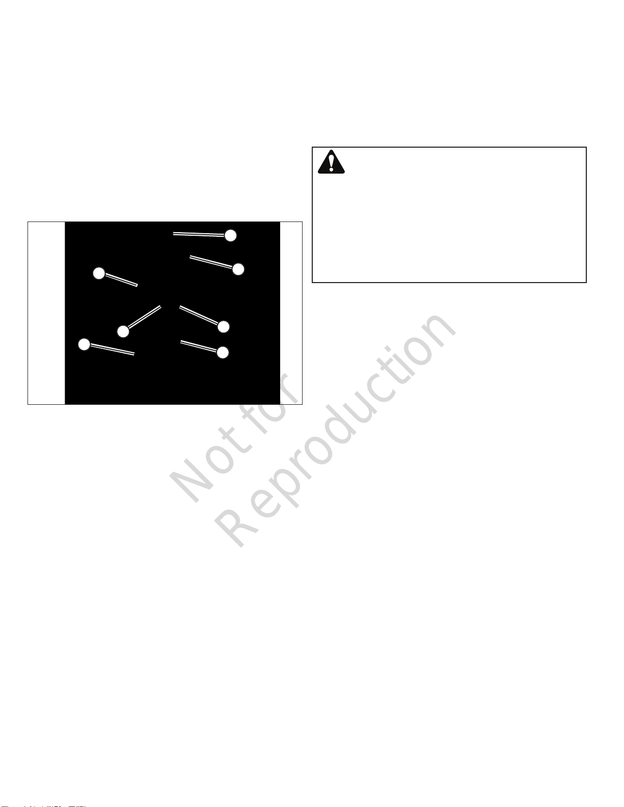
Safety Decals
Before operating your unit, read and understand the follow-
ing safety decals. The cautions, warnings, and instructions
are for your safety. To avoid personal injury or damage to the
unit, understand and follow all the decals.
WARNING
If any safety or instructional decals become worn or dam-
aged, and cannot be read, order replacement decals from
your dealer.
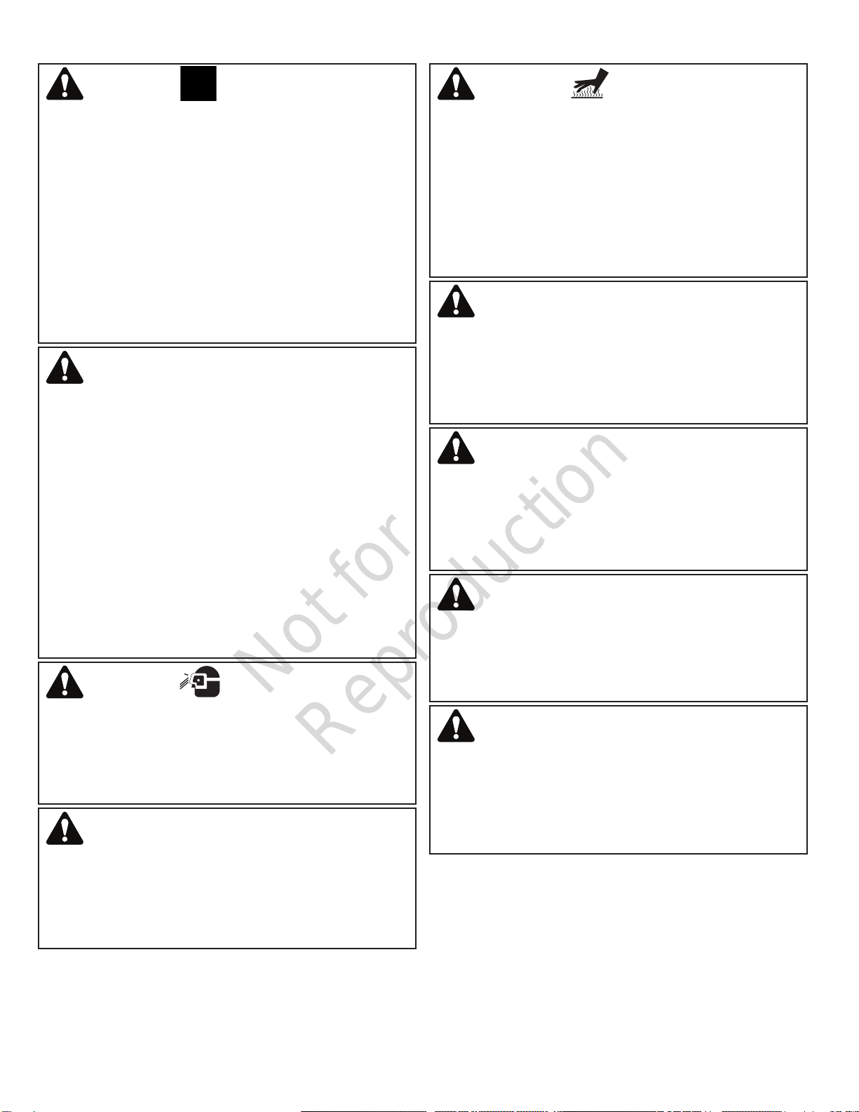
Tire Information
WARNING - Hot surface
could burn exposed skin
which could result in death
or serious injury. Hot com-
ponents must be cool before
handling, or handle hot com-
ponents with heat resistant
gloves.
DANGER - Contacting
High Voltage Components.
Contact with high voltage
components within this com-
partment will result in death
or serious injury. Do not enter
electrical compartments when
engine is running. Always
close cover before operating
the machine.
DANGER - Ground Rod.
Operating the machine with-
out first installing the ground
rod will result in death or seri-
ous injury. Drive the ground
rod into the earth and attach
ground wire to grounding lug.
Emergency Stop
Pre-Heat System
Not for
Reproduction
6www.allmand.com
Fire Extinguisher
Grease Points
Operation Icons
The following table contains operation icons that may be
found on the unit, along with the meaning of each icon.
Icon Meaning Icon Meaning
Read Operator’s
Manual
Earth Ground
On (Power) Off (Power)
Tie Down Lift Point
Diesel Fuel Fuel Tank
Heater Trailer Interior
Light
Hourmeter
Features and Controls
Overview
The Allmand SH-750 Enhanced Flameless Heater delivers
safe and efficient electric heat to areas where conventional
combustion heaters cannot be used.
Ambient air is pulled in through dual intake ducts into an
electric heating element, powered by a 480-volt 3-phase
generator driven by a Caterpillar diesel engine, then forced
out by a belt-driven fan through a single discharge duct. The
result is safe, clean, reliable heat, anytime, anywhere.
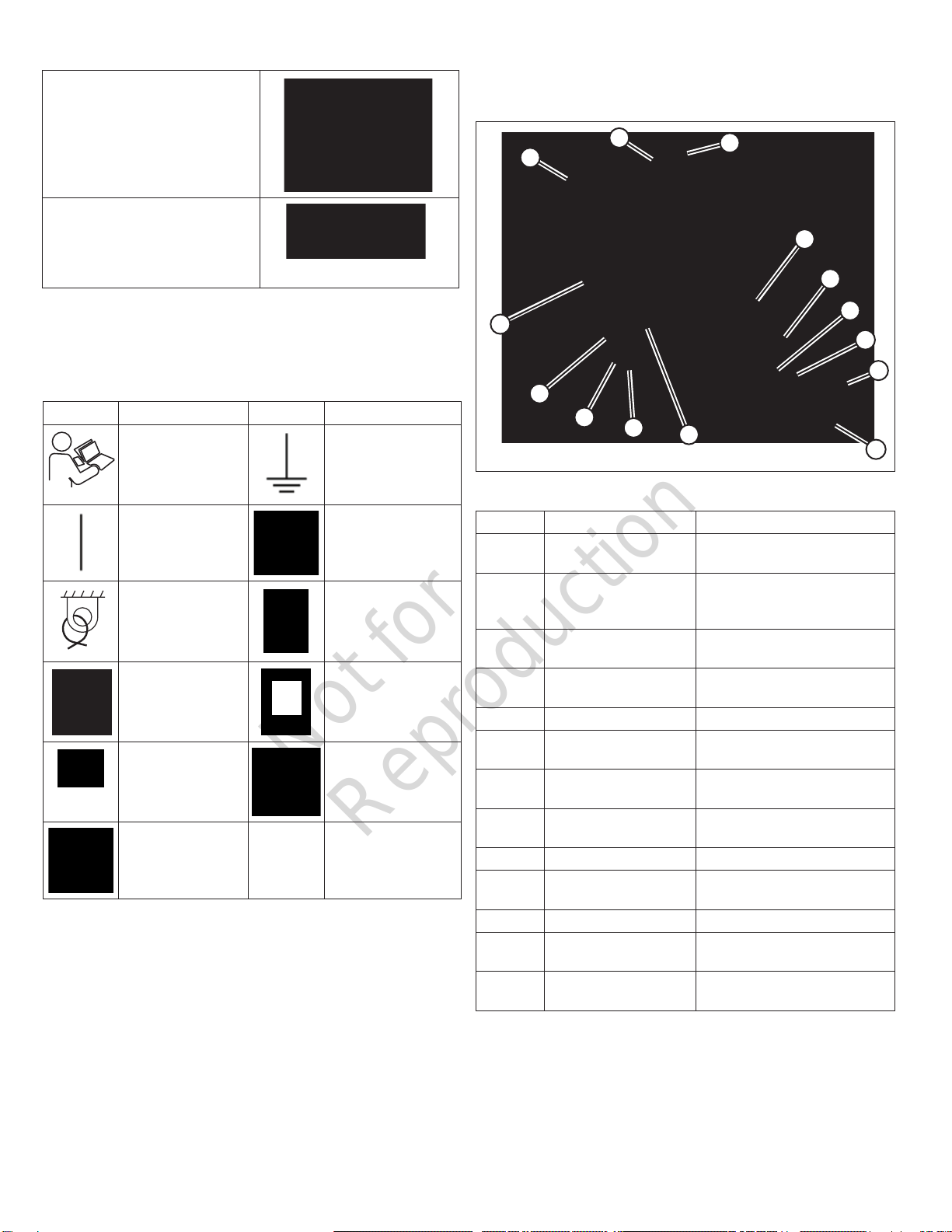
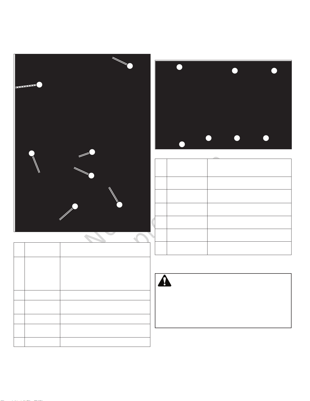
Exterior (Front / Right Side)
Compare Figure 1 with the table following.
Figure 1
E
F
G
D
C
B
A
K
J
H
I
N
L
M
AFire Extinguisher
BTongue Jack (retract-
able)
Supports and levels unit. See
Transporting; Operation.
CBreak-Away Brake
System Switch / Cable
Engages axle brakes in the
event unit separates from tow-
ing vehicle. See Transporting.
DTrailer Lighting Cable Powers trailer lights. See
Transporting.
ETrailer Coupler / Lu-
nette Eye
Couples unit to towing vehicle.
See Transporting.
FSafety Chains (2) See Transporting.
GHeater Discharge
Duct
See Operation.
HTie-Down Point (4 - 2
each side)
See Transporting.
IForklift Pocket (4 - 2
each side)
See Transporting.
JFluid Drain Station See Maintenance.
KEngine Compartment
Access Door
Accesses engine compart-
ment. See Operation.
LEngine Air Cleaner
MExterior Light (4 - 2
each side)
See Operation.
NLift Point (4 - 1 each
corner)
See Transporting.
Not for
Reproduction
7
en
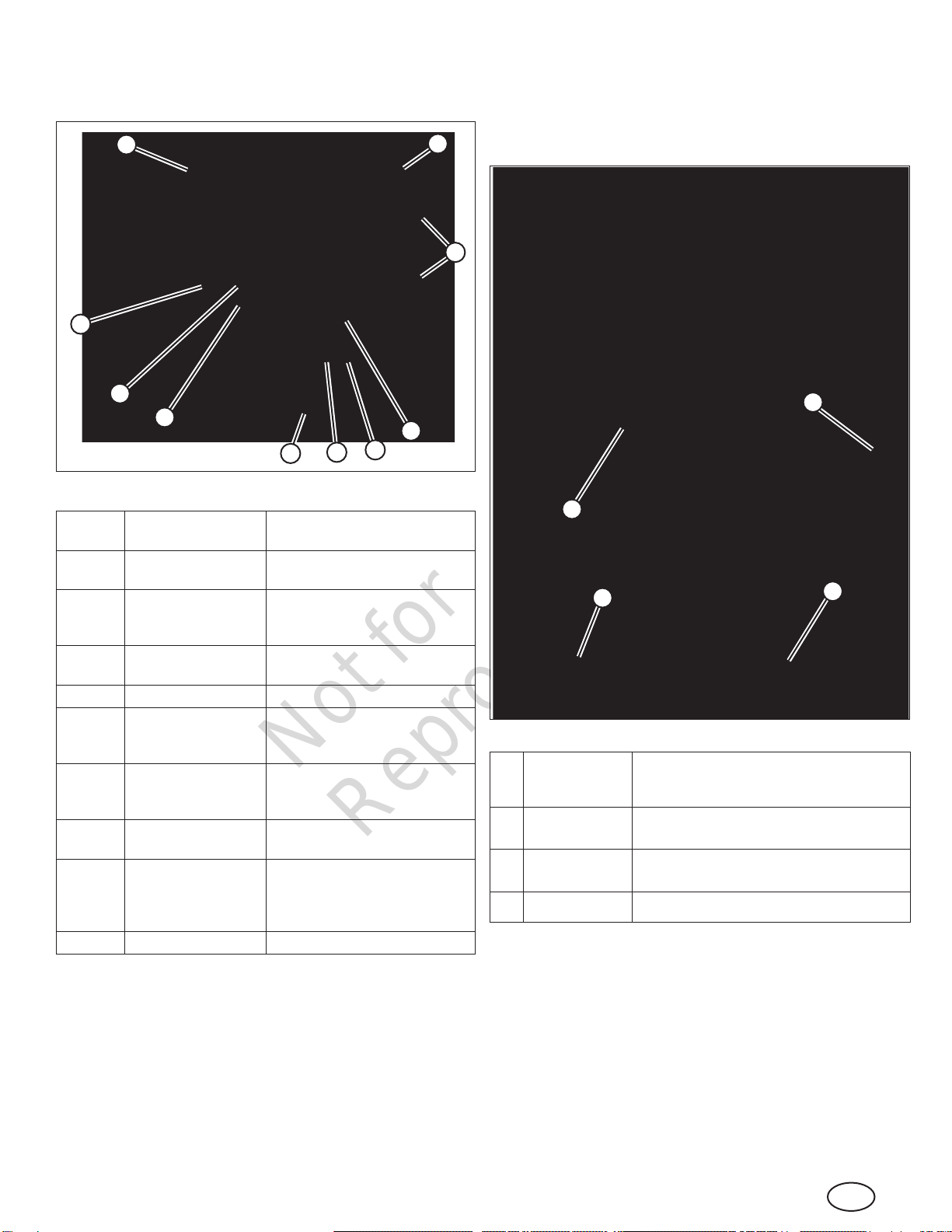
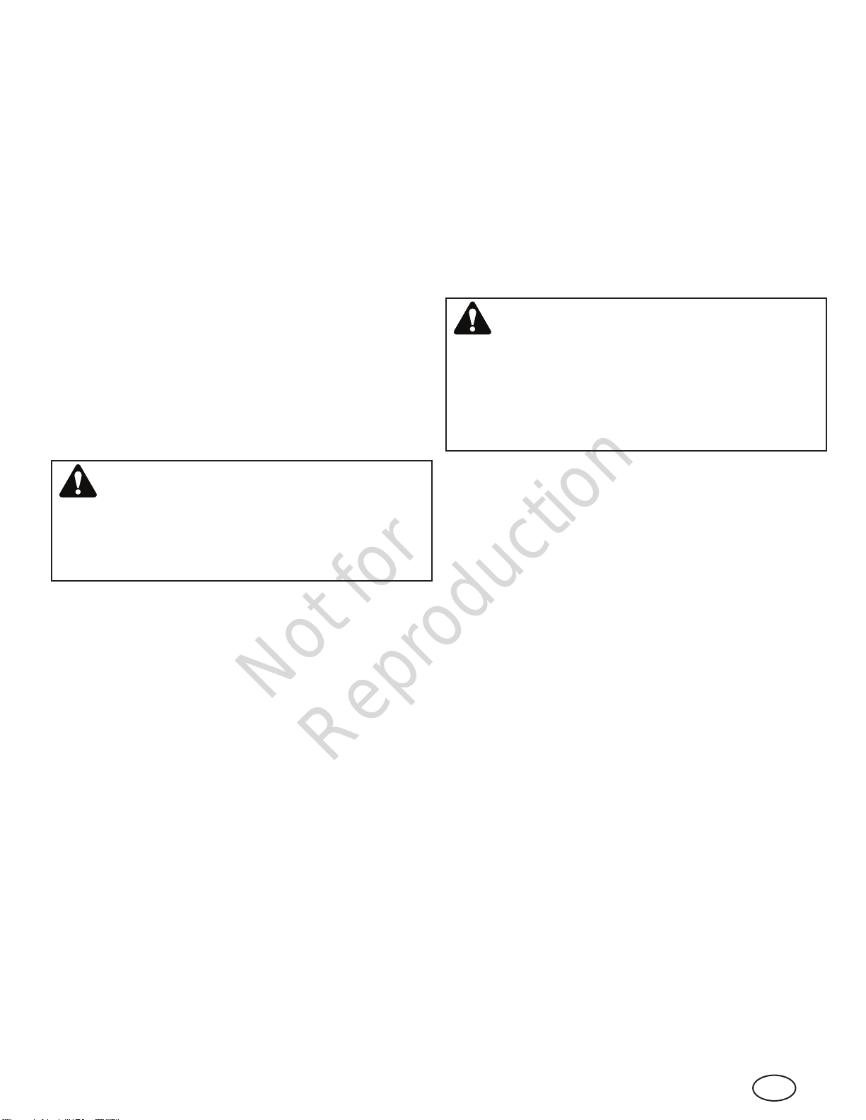
Exterior (Rear / Left Side)
Compare Figure 2 with the table following.
Figure 2
D
C
B
A
E
I
H
F
G
J
ACoolant Fill Access
Plate (on roof)
Access for engine coolant. See
Operation; Maintenance
BHeater Intake Duct
(2)
Heater air intake. See Opera-
tion.
CGround Lug Attachment point for grounding
rod (not supplied). See Opera-
tion.
DLicense Plate
Bracket / Light
ETaillight (2)
FAuxiliary Fluid Con-
tainment Drain (1
each side)
Auxiliary drain points for fluid
containment tray. See Mainte-
nance
GPreheat System Plug Preheats engine coolant,
engine oil, and battery. See
Operation.
HEmergency Stop
Button
All-system shutdown in case of
emergency. See Operation.
IControl Compart-
ment Access Door
Accesses control compartment.
See Features and Controls -
Interior (Control Compartment);
Operation.
JOperational Beacon Indicates unit is operating.
Interior (Control Compartment)
The control compartment is located behind the control com-
partment access door (I, Figure 2).
Compare Figure 3 with the table following.
Figure 3
DC
B
A
AControl Panel Controls operation of engine, heater, and
other accessories. See Features and
Controls -‘Control Panel’;Operation.
BPrime Rod Used to prime engine in the event unit runs
out of fuel. See Operation.
CDoor Lock Rod Locks control compartment access door in
open position. See Operation.
DFuel Cap See Operation.
Not for
Reproduction
8www.allmand.com
Interior (Engine Compartment)
The engine compartment is located behind the engine com-
partment access door (K, Figure 1).
Compare Figure 4 with the table following.
E
D
CG
F
A
B
Figure 4
ACoolant Level
Indicator
Indicates level of engine coolant. See
Operation; Maintenance.
BAir Filter Location of engine air lter (hidden). See
Maintenance.
NOTE: Access to the air lter requires body
panel removal. Replacement should be
performed only by an authorized dealer.
CBattery See Maintenance.
DDoor Lock Rod Locks engine compartment access door in
open position. See Operation.
EGrease Station See Maintenance.
FEngine Oil
Dipstick
Indicates level of engine oil. See Operation.
GEngine Oil Fill Fill point for engine oil. See Operation.
Control Panel
The control panel features controls and informational displays
necessary for the operation of the engine, heater, and other
accessories.
Compare Figure 5 with the table following.
AB C
D
E F G
Figure 5
AEngine Monitor
and Control
Center
Monitors various engine functions;also
controls engine speed. See Operation.
BThermostat Controls target heater temperature. See
Operation.
CDischarge
Temperature
Actual air temperature at heater
discharge duct. See Operation.
DKey Switch Starts engine and powers accessories.
See Operation.
EMaster Switch Turns on power to the unit. See
Operation.
FInterior Light
Switch
Turns on interior compartment lights.
See Operation.
GExterior Light
Switch
Turns on exterior work site lights. See
Operation.
Transporting
WARNING
Operating or towing a machine with worn, damaged or
missing parts can result in death or serious injury. Always
replace worn, damaged or missing parts promptly. Do not
operate or tow this machine until all worn, damaged or
missing parts have been replaced, and proper operation of
the machine has been verified.
Pre-Transport Check List
1. Check that the operator’s manuals are with the heater
trailer, in the manual storage container.
2. Check that all safety decals are legible and in place on
the heater trailer. See ‘Safety Decals’ in the Safety sec-
tion of this manual.
Not for
Reproduction
9
en
3. Check the heater trailer for proper operation:
a. Use an appropriate means to safely support the trailer
tongue. Check that the tongue jack operates properly.
See ‘Operating The Tongue Jack’.
b. Check that the trailer coupler operates properly, and
that the trailer coupler or lunette eye is securely fas-
tened to the heater trailer tongue. See ‘Using The
Trailer Coupler’ and ‘Lunette Eye’.
c. Check that the safety chains are properly secured to
the heater trailer tongue, and check the safety chains
and hooks for damage. Replace damaged safety
chains and hooks.
d. Check the trailer lighting connector for damage, and
the trailer lighting wires for damage. Replace or repair
damaged lighting connector or wiring.
e. Check the break-away trailer brake system, and make
sure the break-away brake system battery is fully
charged. See ‘Break-Away Brake System’.
f. Check the condition and inflation pressure of the tires.
See ‘Checking the Tire Pressure’ in the Maintenance
section.
WARNING
Towing a trailer with worn, damaged or underinflated tires
could result in death or serious injury. Always replace worn
or damaged tires promptly. Always keep tires inflated to
proper cold tire inflation pressure.
4. Check that the ground lug on the rear of the unit is clean
and undamaged.
NOTE: Ground rod and cable not supplied. Contact your
authorized dealer.
5. Check the engine oil level and add as necessary. See
‘Engine Oil’ in the Maintenance section.
6. Check the engine coolant level and add as necessary.
See ‘Engine Coolant’ in the Maintenance section.
7. Check the engine air cleaner for damage and replace
as necessary. Check the engine air intake system and
make sure all connections are air tight.
8. Check to be sure the heater intake and discharge ducts
are clean, undamaged, and unobstructed.
9. Check to be sure the canvas heater duct covers are in
place over the heater ducts.
10.Check the battery for adequate charge. Use a 12 volt
battery charger to bring the battery back to full charge.
See ‘Maintaining the Battery’ in the Maintenance section.
11.If the trailer was stored with the battery disconnected,
reconnect the battery, negative (-) cable last.
12.Check that there is sufficient fuel in the fuel tank, and
add if needed. See ‘Fueling’ in the Operation section.
13.Check that the engine starts and runs properly. See
‘Operating The Engine’ in the Operation section.
14.Check that the heater operates properly. See ‘Operating
The Heater’ in the Operation section.
15.Check that there is sufficient ducting of the correct diam-
eter for the heater trailer.
NOTE: Ducting not supplied. Contact your authorized
dealer.
16.Make sure all covers and doors are closed and securely
latched.
Preparing The Unit For Towing
WARNING
Towing a trailer with an underrated tow vehicle, or an
underrated or undersized hitch could result in death or
serious injury. Always use a tow vehicle that has a rated
towing capacity that exceeds the Gross Vehicle Weight
Rating (GVWR) of the trailer, and is equipped with the
appropriate size tow hitch rated for the GVWR of the trailer.
1. Check the tow vehicle’s owner / operator manual for
the maximum rated towing capacity. Make sure the tow
vehicle and its trailer hitch are rated to tow the heater
trailer. See ‘Heater Trailer Weight’ for detailed information
on trailer weight.
2. Check the tow vehicle’s lighting connector and make
sure it will mate with the trailer lighting connector on the
heater trailer. Check that the auxiliary power wire on the
tow vehicle is connected and powered to operate the
break-away brake system.
3. The heater trailer is equipped with both an SAE J684
coupler (for 2-5/16 inch / 59 mm diameter ball), and
an SAE J847 lunette eye (3 inches / 75 mm diameter).
Determine which is to be used for towing the trailer. See
‘Trailer Coupler / Lunette Eye’ for detailed information on
changing between the trailer coupler and the lunette eye.
4. Check that the safety chains are properly secured to the
heater trailer tongue, and check the safety chains and
hooks for damage. Replace damaged safety chains and
hooks.
5. Check the trailer lighting connector for damage, and the
trailer lighting wires for damage. Replace or repair dam-
aged lighting connector or wiring.
6. Check the break-away trailer brake system, and make
sure the break-away brake system battery is fully
charged. See ‘Break-Away Brake System’ for detailed
information on the break-away brake system.
7. Check the condition and inflation pressure of the tires.
See ‘Checking the Tire Pressure’ in the Maintenance
section for detailed information on tires and tire inflation
pressures.
Not for
Reproduction
10 www.allmand.com
WARNING
Towing a trailer with worn, damaged or underinflated tires
could result in death or serious injury. Always replace worn
or damaged tires promptly. Always keep tires inflated to
proper cold tire inflation pressure.
8. Use an appropriate means to support the trailer tongue.
Check that the tongue jack operates properly. See
‘Operating The Tongue Jack’.
9. Connect the trailer coupler or lunette eye to the tow vehi-
cle trailer hitch or pintle hook. Connect the safety chains
and trailer lighting connector to the tow vehicle. See
‘Connecting The Trailer To The Tow Vehicle’ for detailed
information.
10.Make sure all covers and doors are closed and securely
latched.
Trailer Coupler / Lunette Eye
The heater trailer can be equipped with either a standard
adjustable-height trailer coupler or lunette eye. The SAE
J684 trailer coupler for a 2-5/16 inch / 59 mm diameter ball
is rated at 15,000 pounds (6,804 kg) GVWR with a 2,250
pound (1,021 kg) tongue weight. The 3-inch (75 mm) diama-
ter lunette eye, conforming to the requirements of SAE J847,
is rated at 25,000 pounds (11,340 kg) GVWR with a 3,000
pound (1,361 kg) tongue weight.
To change between the trailer coupler and lunette eye:
1. Check the tongue, trailer coupler and lunette eye for
missing and damaged parts. Replace any part that is
missing or damaged.
2. Remove the two lock nuts and hex head screws (A,
Figure 6) securing the trailer coupler (B) or lunette eye
(C) to the tongue. Discard the lock nuts.
3. Select either the trailer coupler or lunette eye (whichever
is required to couple the heater trailer to your tow vehi-
cle), and position it at the front of the tongue. Determine
the height which works best for your tow vehicle.
4. Insert the two hex head screws removed in Step 2
through the appropriate holes in the tongue and trailer
coupler or lunette eye.
5. Install new lock nuts (Grade 5 or stronger) onto the two
hex head screws and tighten securely.
WARNING
Failure to securely tighten the hardware securing the trailer
coupler or lunette eye to the heater trailer tongue could
cause the heater trailer to separate from the tow vehicle,
resulting in death or serious injury. Always check and
securely tighten the hardware holding the trailer coupler or
lunette eye to the tongue.
Figure 6
A
B
C
Connecting The Heater Trailer To The
Tow Vehicle
1. Place wheel chocks (not supplied) against the front of the
front wheels, and against the back of the rear wheels, on
both sides of the heater trailer.
2. Use the tongue jack to raise the trailer coupler or lunette
eye above the tow vehicle’s hitch ball or pintle hook. See
‘Operating The Tongue Jack’.
3. Position the tow vehicle’s hitch ball or pintle hook under
the trailer coupler or lunette eye.
4. Lower the trailer coupler or lunette eye onto the hitch ball
or pintle hook with the tongue jack.
5. Lock the trailer coupler or pintle hook. See ‘Using The
Trailer Coupler’ or ‘Using A Pintle Hook’ for detailed cou-
pling information.
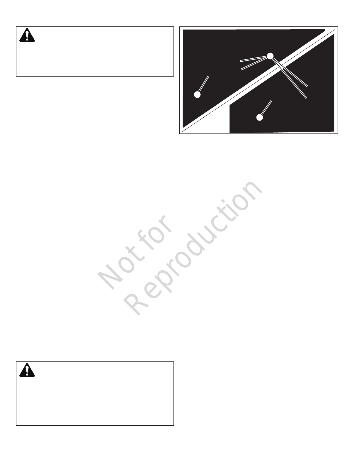
6. Attach the safety chains (A, Figure 7) to the tow vehicle’s
hitch frame. Cross the chains under the tongue as
shown in Figure 7. Leave enough slack in the chains to
allow for turns, but not so much that the chains will con-
tact the road surface.
7. Connect the trailer lighting connector (A, Figure 8) to the
tow vehicle’s connector (B). Make sure the trailer lighting
harness has adequate length to prevent disconnection
when turning, but not so much length that the harness
will contact the road surface. Check the stop, turn sig-
nal, tail, side marker and license plate lamps for proper
operation.
8. Connect the break-away brake switch cable (C, Figure 8)
to the tow vehicle (D). See ‘Break-Away Brake System’
for detailed information on the break-away brake system.
9. Raise the tongue jack all the way, and retract the jack
foot into the transport position. See ‘Operating The
Tongue Jack’.
10.Remove the wheel chocks from both sides of the heater
trailer wheels.
Not for
Reproduction
11
en
Figure 7
A
Figure 8
A
B
C
A
Operating The Tongue Jack
The heater trailer is equipped with a tongue jack to support
the trailer tongue and to level the trailer front-to-rear.
To lower the tongue jack (raise the front of the trailer)
• Turn the jack handle (A, Figure 9) clockwise (B).
To raise the tongue jack (lower the front of the trailer)
• Turn the jack handle (A, Figure 9) counter-clockwise (C).
To extend or retract the jack foot
1. Use an appropriate means to support the trailer tongue.
2. Remove the pin (D, Figure 9) securing the jack foot (E) to
the tongue jack.
WARNING
Removing the jack foot pin without supporting the trailer
tongue could cause the jack to collapse, resulting in death
or serious injury. Always make sure the trailer tongue is
safely supported by appropriate means prior to removing
the jack foot pin.
3. Extend or retract the tongue jack foot as needed.
4. Secure the jack foot with the locking pin. Be sure to lock
the pin in place.
Figure 9
A
E
B
C
D
Using The Trailer Coupler
The heater trailer is equipped with a heavy duty SAE trailer
coupler rated for Gross Vehicle Weight Rating (GVWR) of
15,000 pounds (6,804 kg). This coupler complies with SAE
J684 and VESC V-5 standards.
To couple the trailer to the tow vehicle
1. Pull up on the locking trigger (A, Figure 10), and lift the
locking lever (B, shown lifted).
2. Adjust the coupler to the hitch ball (F, Figure 10) by
pushing the channel lock (D) up, away from the adjusting
nut (E).
3. Tighten the adjusting nut by turning the nut clockwise,
or loosen by turning counter-clockwise. Proper adjust-
ment is obtained when the coupler is as tight as possible
on the ball and the locking lever can still be opened and
closed.
NOTE: Check adjustment frequently and tighten the
adjusting nut as necessary.
Not for
Reproduction
12 www.allmand.com
4. Make sure the hitch ball is completely engaged in the
coupler socket (C, Figure 10).
5. Push the locking lever down into the locked position.
Insert the locking pin (G, Figure 10) into the hole in the
locking lever, or use a padlock for added security.
6. Check that the coupler is securely attached to the ball
hitch.
To uncouple the trailer from the tow vehicle
1. Remove the locking pin (or padlock, if used) from the
hole in the locking lever.
2. Pull up on the the locking trigger, and lift the locking lever.
To couple the trailer to the tow vehicle:
Figure 10
B
A
FG
E
D
C
Using A Pintle Hook
The 3-inch (75mm) diameter lunette eye meets the require-
ments of SAE J847 for Gross Vehicle Weight Rating (GVWR)
of 25,000 pounds (11,340 kg). Couple the lunette eye to
a pintle hook meeting the requirements of SAE J847 for a
GVWR of not less than 25,000 pounds (11,340 kg).
When using the lunette eye with a pintle hook, follow the pin-
tle hook manufacturer’s instructions for coupling and locking
the lunette eye to the pintle hook, and uncoupling the lunette
eye from the pintle hook.
Break-Away Brake System
The heater trailer is equipped with electric brakes and a
break-away brake system. The break-away brake system
is designed to bring the heater trailer to a stop by activating
the electric brakes should the heater trailer become discon-
nected from the tow vehicle while moving.
The auxiliary power wire on the tow vehicle must be con-
nected and powered for this system to work.
The break-away brake system is not intended to be used as
a parking brake.
The break-away brake system consists of a break-away box
with 12 volt battery, a break-away brake switch, and a break-
away brake switch cable.
The break-away brake box is equipped with a battery test
button to check the battery condition. The battery should be
charged and tested before towing the trailer.
To check the break-away brake system
WARNING
Towing the heater trailer when the break-away brake sys-
tem battery charge is low, or when the electric brakes are
not functioning properly could result in death or serious
injury should the heater trailer become disconnected from
the tow vehicle while moving. Always perform the break-
away brake system tests prior to towing the heater trailer.
Always repair the break-away brake system if the system is
not operating properly.
1. Before connecting the tow vehicle trailer lighting cable
to the heater trailer, push the “Test” button on the break-
away brake box. The green light indicates a charged bat-
tery, while a red light indicates that the battery charge is
low.
2. If the battery charge is low, recharge the battery before
towing the trailer. To recharge the battery, connect the
tow vehicle’s trailer lighting cable to the heater trailer. An
amber light indicates that the battery is charging.
3. With a fully charged battery, test the break-away brake
system. Pull firmly on the break-away brake switch cable
until the pin disconnects from the break-away brake
switch. The battery should activate the electric brakes.
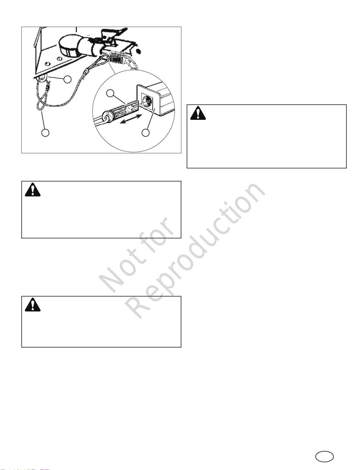
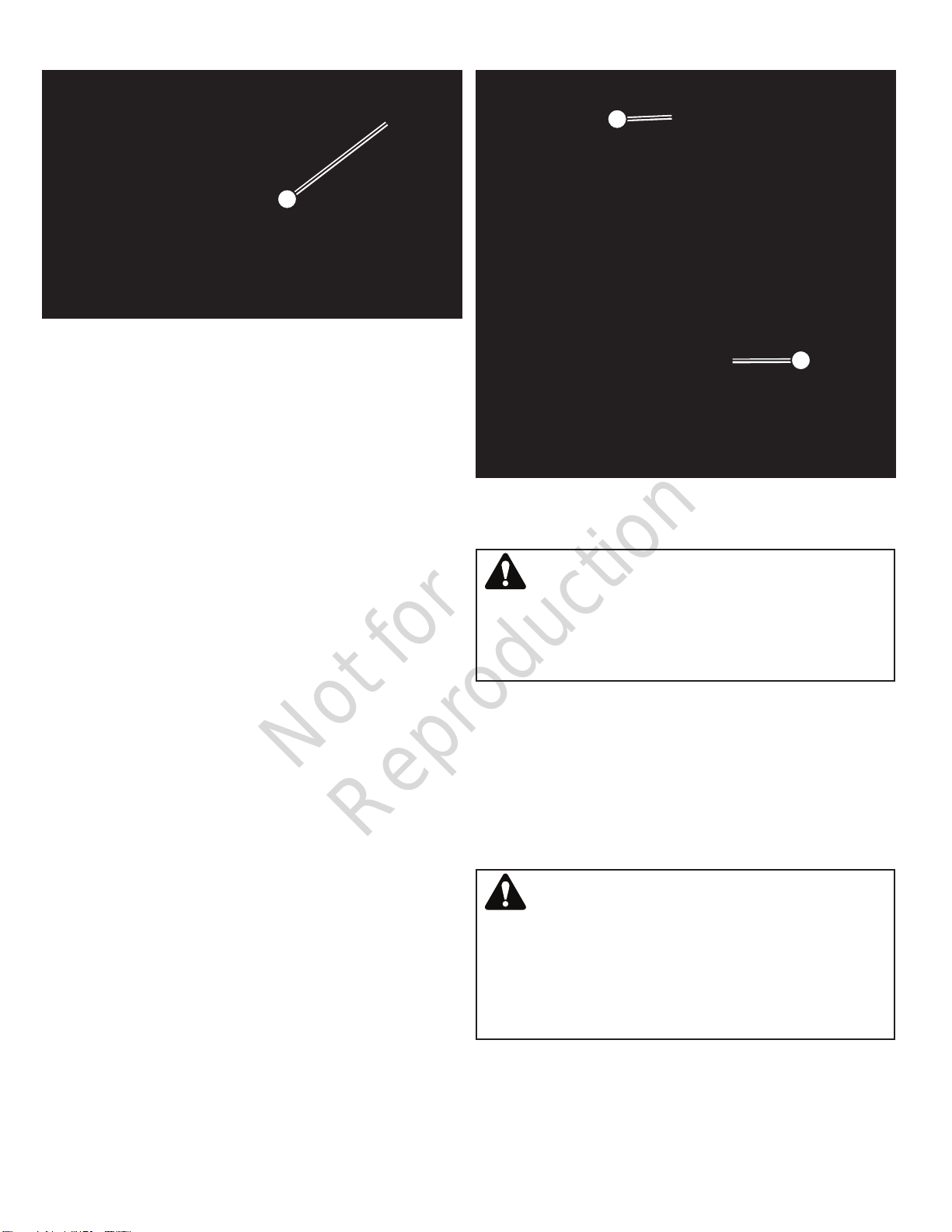
To connect the break-away brake switch cable to the
tow vehicle
1. Pull the pin (A, Figure 11) out of the break-away brake
switch (B).
NOTE: Image is representative, and may differ according
to model.
2. Locate the safety chain pocket on the tow vehicle that is
on the same side as the break-away brake switch. Do
not cross the break-away brake switch cable to the oppo-
site side safety chain pocket, as this could cause the
break-away brake switch to fail. Do not cross over the
hitch ball, as the cable may become disconnected as the
tow vehicle moves over rough roads.
3. Route the pin through the safety chain pocket (C, Figure
11), then through the break-away brake cable loop (D).
4. Re-insert the pin in the break-away brake switch.
NOTE: Some break-away brake switch cables feature a
carabiner that hooks to the safety chain pocket. Refer to
Figure 8.
Not for
Reproduction
13
en
Figure 11
A
B
C
D
Heater Trailer Weight
WARNING
Towing the heater trailer when it is loaded beyond the
Gross Vehicle Weight Rating (GVWR) as stated on the
serial plate could result in death or serious injury. Always
maintain a GVWR less than the GVWR stated on the serial
plate.
The heater trailer is an SAE Class 4 trailer, with a Gross
Vehicle Weight Rating (GVWR) as stated on the serial plate
and in the Specifications section of this manual. Do not
exceed the GVWR by attempting to carry additional tools or
equipment. Do not carry riders. See Safety.
Towing The Heater Trailer
WARNING
Excessive speed when towing the trailer could result in
death or serious injury. Always maintain a safe towing
speed for road conditions. Never exceed 55 MPH (90
km/h) when towing the heater trailer.
The rated maximum highway towing speed for the heater
trailer is 55 MPH (90 km/h). Be sure to check your state or
province laws regarding maximum legal towing speeds for
trailers.
When towing the heater trailer off-highway or on rougher
terrain, the maximum towing speed is 20 MPH (32 km/h).
Slower speeds may be required for very rough terrain.
The heater trailer is designed to be towed with the engine
and heater units shut down.
Disconnecting The Heater Trailer From
The Tow Vehicle
1. Select a firm, level and stable surface at the work site.
See ‘Work Site Considerations’ in the Operation section.
2. Position the heater trailer with the tow vehicle so that the
heater discharge duct (right side of the trailer) is toward
the area to be heated.
3. Chock the front and rear wheels on both sides of the
heater trailer.
WARNING
Attempting to move or position the heater trailer by manu-
ally pushing or pulling it could present a crush hazard
resulting in death or serious injury. Always position the
heater trailer with the tow vehicle, chock the wheels and
lower the tongue jack before uncoupling the trailer from the
tow vehicle.
4. Disconnect the trailer lighting connector from the tow
vehicle’s connector.
5. Extend the tongue jack foot, and lower the tongue jack to
support the front of the heater trailer. See ‘Operating The
Tongue Jack’.
6. Disconnect the trailer coupler or lunette eye from the tow
vehicle. See ‘Using The Trailer Coupler’ or ‘Using A Pintle
Hook’.
7. Use the tongue jack to raise the trailer coupler or lunette
eye above the tow vehicle’s hitch ball or pintle hook.
8. Disconnect the safety chains from the tow vehicle’s hitch
frame.
9. Disconnect the break-away brake cable from the tow
vehicle.
10.Move the tow vehicle clear of the heater trailer.
Transporting On A Trailer
The heater trailer is equipped with four tie down points. See
Features and Controls.
Always secure the heater trailer with appropriate chains or
straps. Do not apply more than 600 pounds (272 kg) force
on the chains or straps.
The truck operator is responsible for securing the load prop-
erly to his trailer.
Not for
Reproduction
14 www.allmand.com
Lifting The Heater Trailer
WARNING
Attempting to lift the heater trailer with a lifting device that
is underrated or damaged could result in death or serious
injury. Always make sure the lifting device is rated to lift
the weight of the heater trailer. Make sure that the lifting
device is not damaged and is in operable condition before
beginning the lift.
WARNING
Standing or walking under elevated equipment could
result in death or serious injury. When elevating or lifting
the heater trailer, always keep clear of the area around
and under the heater trailer, and do not allow others in the
area.
Lifting Eyes
The heater trailer is equipped with four lifting eyes at the top
of the trailer. See Features and Controls for lifting eye loca-
tions. See ‘Heater Trailer Weight’ for the weight of the heater
trailer.
Each lifting eye is rated for 10,000 pounds (4,536 kg). Use
all four lifting eyes when attempting to lift the heater trailer.
The lifting eyes are intended carry the weight of the heater
trailer only, and no additional weight.
The heater trailer is not intended to be suspended for long
periods of time.
Forklift Pockets
The heater trailer is equipped with four forklift pockets, two on
either side. One is located forward of the front wheels, and
one between the front and rear wheels.
Use a forklift with a lifting capacity greater than the weight of
the heater trailer. See ‘Heater Trailer Weight’.
Operation
Work Site Considerations
Prior to setting up and operating the heater trailer, the opera-
tor must determine where to place it on the work site. When
placing the heater trailer, consideration must be given to
ground conditions, proximity to combustible or flammable
material, and ventilation.
It is the operator’s responsibility to ensure that the heater
trailer is properly and safely positioned on a stable surface at
the work site. Be sure to follow rules or instructions for your
work site for locating the heater trailer.
Ground Conditions
The heater trailer must be placed on a firm stable surface
that will support the total weight of the trailer, and support the
force exerted on the ground at the tongue jack. The surface
should be level, but must not exceed a grade of 2.5% (1.4°
incline) in any direction. Grades greater than 2.5% may
cause the heater trailer to roll away. Always chock the front
and rear wheels on both sides of the heater trailer prior to
disconnecting the heater trailer from the tow vehicle.
Proximity To Combustible Or Flammable
Material
The heater must be kept away from combustible or flam-
mable material. Maintain a distance of at least 8 feet (2.5 m)
from the heater discharge duct, and 5 feet (1.5 m) from the
heater air intake ducts, from any combustible or flammable
material.
Carbon Monoxide Asphyxiation
WARNING
Operating the engine or the heater units in a non-ventilated
enclosed area could result in death or serious injury.
Always operate the engine and the heater units in a well
ventilated area.
The engine exhaust contains carbon monoxide gas which
can cause asphyxiation when the engine is run in an
enclosed area. Make sure that the heater trailer is in a well
ventilated area before starting the engine.
NOTE: Because this unit features an electric heating ele-
ment, carbon monoxide gas is not present at the heater dis-
charge duct.
Using A Ground Rod
The heater trailer utilizes an earth grounding system, a safety
device that reduces the chance of personal injury from stray
electric currents. Use of this earth grounding system is
strongly recommended whenever the heater trailer is in use.
The heater trailer is equipped with a ground lug, located on
the left rear of the trailer. See Figure 12. A ground rod and
grounding cable are also required, and can be obtained
through your authorized dealer.
It is the user’s responsibility to determine the requirements
and / or applicability of national, state or province and local
electrical code, which governs the use of a ground rod.
To install the ground rod
1. Locate a point on the ground not more than 5 feet (1.5 m)
from the ground lug (A, Figure 12). Drive the ground rod
(B) into the earth at this point.
2. Attach one end of the grounding cable (C, Figure 12) to
the ground rod.

Not for
Reproduction
15
en
3. Loosen the cable mounting screw inside the ground
lug. Insert the loose end of the grounding cable up into
the ground lug, then tighten the cable mounting screw
against the cable end.
To remove the ground rod
1. Loosen the cable mounting screw, remove the ground-
ing cable from the ground lug, then retighten the cable
mounting screw.
2. Remove the ground rod from the earth. Be careful not to
damage the grounding cable when removing the ground
rod.
3. Wind the grounding cable around the ground rod, and
store in a safe place.
Figure 12
A
B
C
Compartment Access Doors
Most of the controls and maintenance points for the heater
trailer are located behind two access doors, one on either
side of the heater trailer. Both doors operate similarly.
To open
1. Pull the latch (A, Figure 13) to open the compartment
access door. (Control compartment access door shown).
2. Lock in the open position by inserting the lock pin (C)
into the hole in the door lock rod (B). Be sure the hole is
on the outside of the trunion.
To close
1. Pull the pin securing the door lock rod in the locked posi-
tion.
2. Close and latch the door. (Each door features a key lock
for added safety and security.)
Figure 13
B
C
A
Fueling
WARNING
Attempting to fuel the heater trailer with the engine run-
ning could cause fire, resulting in death or serious injury.
Always make sure the engine is shut down before adding
fuel to the fuel tank.
The heater trailer is equipped with a 270-gallon (1022 L) fuel
tank. The fuel cap (A, Figure 14) is located inside the control
compartment to the left, beneath the control panel.
See ‘General Engine Fuel Information’ in the Maintenance
section for information on the engine fuel that may be used.
NOTICE
Using engine fuels other that those recommended could
cause damage to your engine or its emission control system
and void the engine manufacturer’s warranty. Always read
and follow the engine fuel recommendations.
The fuel level (% max fuel capacity) is diplayed in the engine
monitor and control center. See ‘Operating the Engine’.
Adding Fuel
1. Open the control compartment access door and lock in
the open position. See ‘Compartment Access Doors’.
2. Turn the fuel cap (A, Figure 14) counterclockwise 1/4 turn
and remove.
Not for
Reproduction
16 www.allmand.com
3. Add fuel to the tank. See ‘General Engine Fuel
Information’ in the Maintenance section.
4. Replace the fuel cap and turn clockwise 1/4 turn to lock.
Figure 14
A
Preparing To Operate The Heater Trailer
1. Place wheel chocks against the front and rear wheels on
both sides of the heater trailer.
2. Level the heater trailer front to back with the tongue jack.
See ‘Operating The Tongue Jack’ in the Transporting sec-
tion.
3. Open the engine compartment access door and secure
with the lock pin. See ‘Compartment Access Doors’.
4. Check the engine oil level. See ‘Engine Oil’ in the
Maintenance section.
NOTICE
Failure to maintain engine oil level could result in engine
damage.
5. Check the engine coolant level. See ‘Engine Coolant’ in
the Maintenance section.
NOTICE
Failure to maintain engine coolant level could result in engine
damage.
6. Check the fuel level in the fuel tank and add as needed.
See ‘Fueling’.
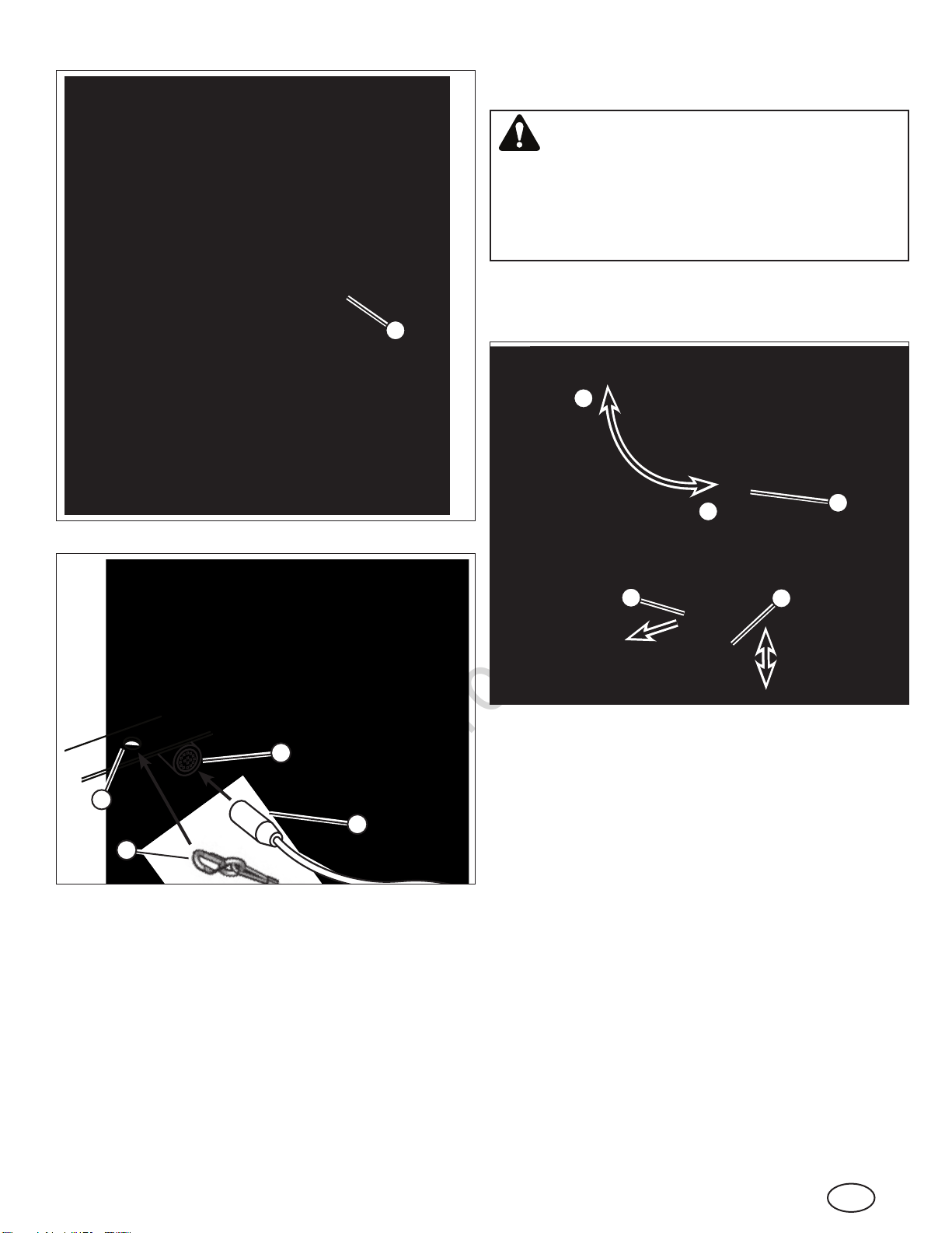
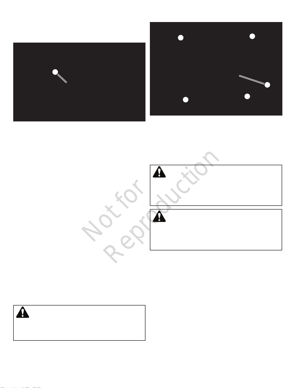
7. Remove the canvas covers (A, Figure 15) from the heater
intake ducts and the heater discharge duct. Unhook
the elastic cover cord from the four corner hooks (B),
and slip the cover from the heater duct. (The cover is
attached by a lanyard to the heater trailer.)
WARNING
Failure to remove the heater duct covers could cause a
fire, resulting in death or serious injury. Always remove the
heater duct covers before operating the heater trailer.
Figure 15
A
B
B
B
B
Heater Ducting
The heater intake and discharge ducts on the heater trailer
are designed to be fitted with 16-inch (406 mm) diameter
flexible heater ducting, available through your authorized
dealer.
WARNING
Do not install or remove heater ducting while the heater
trailer is in operation. High-velocity discharge could result
in death or serious injury. Always install heater ducting
before starting the heater trailer.
WARNING
Use of ducting other than that designed for use with heater
trailers could cause a fire, resulting in death or serious inju-
ry. Always use ducting designed only for use with heater
trailers.
To install heater ducting
1. Remove the canvas covers from the heater intake
ducts and the heater discharge duct. See ‘Preparing To
Operate The Heater Trailer’.
2. Open the clamps (A, Figure 16, not all models) by mov-
ing the clamp levers outward away from the heater duct.
3. Install the cuff of the flexible heater ducting (B, Figure
16) over the heater duct. Secure with the clamps (if
equipped). Adjust the threaded clamp pads (C) to make
sure the ducting is secured to the heater duct.

Not for
Reproduction
17
en
Figure 16
B
A
A
C
C
To remove heater ducting
1. Open the clamps (if equipped) and pull the cuff of the
flexible heater ducting from the heater duct.
WARNING
Do not remove the heater ducting during or immediately
after operation. The heater ducting and the heater duct
will be extremely hot, and could result in death or serious
injury. Shut down the heater trailer and allow ample time
for the components to cool before removing the heater
ducting.
2. Replace the canvas covers onto the heater ducts. See
‘Preparing To Operate The Heater Trailer’.
Operating The Engine
Before starting the engine
1. Check to be sure the canvas covers are removed from
the heater intake and discharge ducts. See ‘Preparing To
Operate The Heater Trailer’.
2. Check to be sure the emergency stop is disengaged.
See ‘Emergency Stop’.
To start the engine
1. Open the control compartment access door and lock in
the open position. See ‘Compartment Access Doors’.
2. Turn the master switch (A, Figure 17) to the ON position.
NOTE: Turning the master switch to the ON position pro-
vides power to the interior light switch (D) and exterior
light switch (E).
3. Turn the key switch (B, Figure 17) to the RUN position.
The glow plug indicator lights (C) on the engine monitor
and control center will illuminate. Wait for the lights to
turn off (approximately 15 seconds).
Turning the key switch to the RUN position also powers
up the engine monitor and control center. See ‘Engine
Monitor and Control Center’.
4. Turn the key switch all the way to the right to the START
position until the engine starts. Release the key switch.
It will remain in the RUN position.
NOTE: If the engine has run out of fuel, you will need to prime
the engine after refueling. Twist the prime rod (A, Figure 18)
counterclockwise to unlock, pull out, pump 3-4 times or until
firm, then push in and twist clockwise to lock.
NOTICE
Operating the starter for more than 10 seconds without allow-
ing time between starting attempts could damage the starter.
Always give the starter time to cool, by allowing at least 30
seconds between starting attempts.
NOTICE
Engaging the starter while the engine flywheel is still rotat-
ing could damage the starter pinion or flywheel ring gear.
Always allow the engine to come to a complete stop before
re-engaging the starter.
B
AD E
Figure 17
C
Not for
Reproduction
18 www.allmand.com
Figure 18
A
To shut down the engine
1. Make sure the heater unit has had ample time (5 - 10
minutes) to cool down. See ‘Operating The Heater Unit’.
2. Turn the key switch to the OFF position.
3. Turn the master switch to the OFF position.
Emergency Stop
The emergency stop, located to the right of the control com-
partment access door (left side of the heater trailer), is a
safety device that shuts down the engine and heater trailer in
the event of an emergency. It is to be used only in instances
when the unit must be stopped immediately, such as the
threat of injury, death, or property damage. Do not use as an
alternative to the key switch or master switch.
NOTICE
Use of the emergency stop when the unit is in full operation
could result in equipment damage, as the unit requires ade-
quate time to cool down.
To engage
Press the emergency stop button (A, Figure 19).
To disengage (reset)
Pull out on the emergency stop button until the button clicks.
NOTE: The unit will not start or operate until the emergency
stop is disengaged.
Pre-Heat System
The heater trailer is equipped with a pre-heat system that
pre-heats the engine coolant, engine oil, and battery prior to
starting.
The pre-heat system should be used at least 30 minutes prior
to starting the engine in temperatures below 32°F (0°C).
To use
Connect a grounded (3 prong) extension cord from the pre-
heat system plug (B, Figure 19) to an appropriate electric
power source (120 volts AC, 60Hz). Disconnect after starting
the engine.
Figure 19
A
B
Jump Starting The Engine
WARNING
Attempting to jump start or charge a frozen battery could
cause explosion resulting in death or serious injury.
Always be sure that the battery is not frozen, split open or
damaged before attempting to charge or jump start it.
In the event that the battery is insufficiently charged to start
the engine, check the battery to make sure it is not frozen,
split open or damaged. If any of these conditions exist,
replace the battery, and do not attempt to jump start or
recharge it.
If these conditions do not exist, it is permissible to jump start
the engine taking care to follow the proper procedure.
To jump start the engine
WARNING
Allowing the ends of the jumper cables to touch each
other or metal surfaces while connected to a battery could
cause sparks that may ignite battery gases resulting in
death or serious injury. Always keep jumper cable ends
from touching each other or metal surfaces while connect-
ing or disconnecting them.
1. To gain access to the battery, open the engine compart-
ment access door and secure in the locked position. See
‘Compartment Access Doors’.
2. Connect one end of the red jumper cable to the positive
(+) terminal of the booster vehicle battery.

Not for
Reproduction
19
en
3. Connect the other end of the red jumper cable to the
positive (+) terminal of the heater trailer battery.
4. Connect the one end of the black jumper cable to the
negative (-) terminal of the booster vehicle battery.
5. Connect the other end of the black jumper cable to an
unpainted surface of the heater trailer engine or chassis.
6. Make sure that the jumper cables are not near any mov-
ing parts of either engine.
7. Start the engine of the booster vehicle and let it idle for
several minutes.
8. Start the engine of the heater trailer and let both engines
run for several minutes.
9. After the engine has started and stabilized, remove the
jumper cables in the reverse order. Remove the black
jumper cable from the unpainted surface of the heater
trailer engine or chassis first. Do not allow the end of this
cable to touch any metal or other jumper cable ends.
10.Remove the remaining cables starting with the black
jumper cable at the negative (-) terminal of the booster
vehicle battery, then the red jumper cable from the posi-
tive (+) terminal of heater trailer battery and finally the red
jumper cable from the positive (+) terminal of the booster
vehicle battery. Do not let the cable ends touch any
metal or each other.
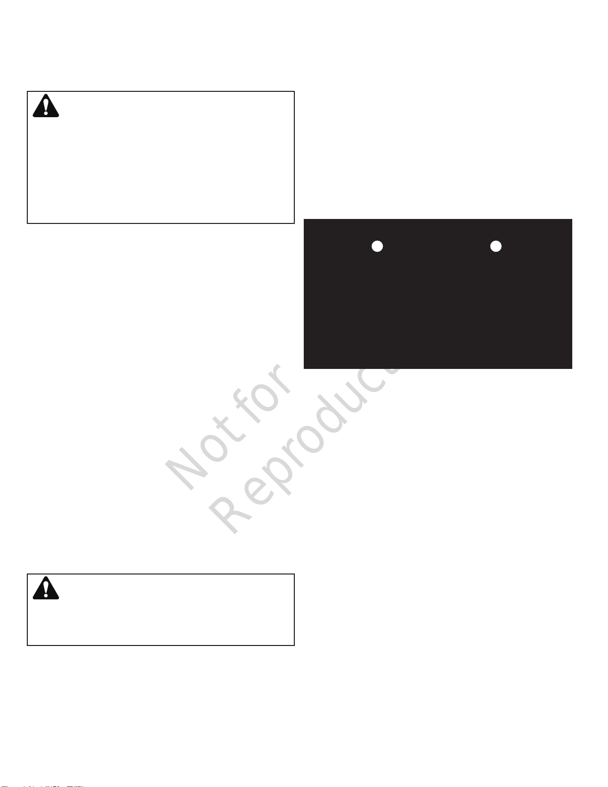
Engine Monitor and Control Center
The engine monitor and control center (Figure 20) monitors
critical engine functions, and controls engine speed.
Turning the key switch to the RUN position powers up the
engine monitor and control center. Once the engine is start-
ed, the following information is displayed on the monitor:
A. Coolant Temperature *
B. Engine RPM *
C. Oil Pressure *
D. Battery Voltage
E. Fuel Level (% of max tank capacity) *
F. Hourmeter
The control center adjusts the engine RPM range from 1000
to 1800, in increments of 50 RPM.
G. Increase Engine RPM
H. Decrease Engine RPM
NOTE: The ‘Menu’ (I) and ‘Enter’ (J) buttons have been pre-
set at the factory, and should not be touched.
* Engine shutdown will occur in the event of:
• High coolant temperature (>245°F (118° C))
• High engine RPM (>1800)
• Low oil pressure (<15 psi)
• Low fuel level (<15%).
See also ‘Automatic Engine Shutdown System’ and
‘Engine Air Intake Shut-Off Valve (Shocker Valve)’.
ABC
DEF
G
I J
H
Figure 20
Automatic Engine Shutdown System
The engine is equipped with an automatic engine shutdown
system. This system will automatically shutdown the engine
in the event of low engine oil pressure or high coolant tem-
perature.
If the engine has automatically shutdown, locate the source
of the failure and repair the failure before re-starting the
engine.
Engine Air Intake Shut-Off Valve (Shocker
Valve)
The heater trailer is equipped with an engine air intake shut-
off valve (shocker valve). The valve is intended to prevent the
diesel engine from going into an overspeed condition in the
event that flammable gas or vapor is present at the engine air
intake. Should an overspeed condition occur, the engine air
intake shut-off valve automatically closes, preventing air from
getting into the cylinders, thereby stopping the engine.
The engine air intake shut-off valve is intended only to protect
the engine against damage from overspeed conditions. It
is not intended to be used as any part or indicator for a per-
sonal protective device, nor does it provide an indication of
whether an area is safe from flammable or explosive gas.
The engine air intake shut-off valve should be tested daily.
To test the engine air intake shut-off valve
1. Start the engine. See ‘Operatng The Engine’.
3. Locate the covered switch on the right side of the control
panel. Lift the cover and move the switch to the up posi-
tion. The engine should shut down immediately. If the
engine shuts down, close the red cover on the switch to
reset the switch to the operational mode.
4. If the engine does not shut down immediately, shut the
machine down with the key switch, and do not use the
machine. Close the cover on the switch to reset the
switch to the operational mode. Tag the machine “Do not
Not for
Reproduction
20 www.allmand.com
operate”, and notify your service or maintenance depart-
ment to get the machine repaired.
To reset the engine air intake shut-off valve
DANGER
Resetting and re-starting the engine after the engine air
intake shut-off valve has automatically shut down the
engine could ignite an explosive atmosphere that will result
in death or serious injury. Always leave the area immedi-
ately when the engine air intake shut-off valve automati-
cally shuts down the engine, and do not return until safety
and supervisory personnel have given an “all clear” to
return to the area.
1. If the air intake shut-off valve has tripped and shut down
the engine automatically, leave the area immediately and
follow the safety instructions and procedures for your job
site. Do not reset or restart the engine until the source of
the problem has been determined, and safety and super-
visory personnel at your job site have given an “all clear”
to return to the area.
2. When permission is given to return to the area, open the
control compartment access door and lock in the open
position, and locate the blue knob on the engine air
intake shut-off valve, located on the right side of the con-
trol panel. Turn the knob so that it aligns with the intake
hoses to and from the valve body. You will hear and feel
a distinct “click” as the engine air intake shut-off valve is
reset to the operating position.
3. Start the engine. See ‘Operating The Engine’.
Operating The Heater Unit
The heater trailer is equipped with an electric, thermostat-
controlled heat exchanger, which results in clean, safe heat.
Max heat output is 750,000 BTUs/hr; maximum temperature
output is 300° F (150° C). See Specifications.
To operate the heater unit
1. Remove the heater duct covers and install heater duct-
ing. See ‘Preparing to Operate the Heater Trailer’ and
‘Heater Ducting’.
WARNING
Failure to remove the heater duct covers could cause a
fire, resulting in death or serious injury. Always remove the
heater duct covers before operating the heater trailer.
2. Start the engine. See ‘Operating the Engine’.
3. Adjust the thermostat (A, Figure 21) to the lowest tem-
perature setting (50°F (10°C)).
4. Allow the engine to run until coolant temperature reaches
150° F (65°C).
5. Increase engine RPMs to 1400 - 1800. See ‘Engine
Monitor and Control Center’.
6. Adjust the thermostat to the desired target discharge
temperature. (Temperature range of heater unit is 50°F
(10° C) to 300°F (150°C)).
7. Monitor discharge temperature (B, Figure 21). Depending
upon ambient air temperature, it may take several min-
utes for the discharge temperature to rise to the target
temperature.
8. Continue to monitor engine and heater information
throughout unit operation. Adjust as needed.
9. In the event of an emergency, engage the emergency
stop. See ‘Emergency Stop’.
A B
Figure 21
-
+
To shut down the heater unit
1. Adjust the thermostat to the lowest temperature setting
(50° F (10°C)).
2. Decrease engine RPMs to 1200.
3. Allow 5-10 minutes for the heater unit to cool down.
4. Decrease engine RPMs to 1000.
NOTE: At engine speeds lower than 1200 RPMs, the
generator ceases to produce electricity.
5. Shut down the engine. See ‘Operating the Engine’.
Shutting Down The Heater Trailer
1. Shut down the heater unit. See ‘Operating the Heater
Unit’.
2. Shut down the engine. See Operating the Engine.
3. Remove heater ducting. See ‘Heater Ducting’.
4. Replace canvas covers onto heater ducts. See
‘Preparing to Operate the Heater Trailer’.
5. Close and latch compartment doors.
Table of contents
Languages:
Other Allmand Heater manuals


Popular Heater manuals by other brands

Kambrook
Kambrook SNUGASABUG FAN HEATER KFH20 user manual

Emerson
Emerson Fisher Yarway AT-25 instruction manual

Harvia
Harvia PO11 Instructions for installation and use

Euromatic
Euromatic ERC24B instruction manual

Frost Fighter
Frost Fighter IDHQR Series Installation - Operation/Maintenance Instructions and Parts List

Royal Sovereign
Royal Sovereign HFN-02 user manual


