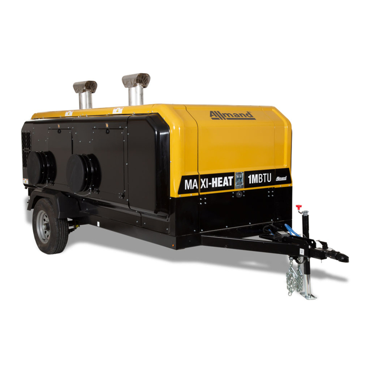
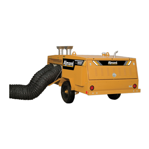
Allmand Maxi-Heat Series Product manual

MODEL MH-1000
OHV 600
ALLMAND BROS. INC
P.O. BOX 888
HOLDREGE, NE 68949
PHONE: 308/995-4495, 1-800/562-1373
FAX: 308/995-5887
PARTS FAX: 308/995-4883
MAXI-HEAT® SERIES
MAXI-HEAT®SERIES
OPERATOR’S AND PARTS MANUAL
August 2005
For Parts and Updates visit Allmand on the Web at www.allmand.com
80025369
Not for Reproduction

OPERATORS MANUAL
Inspection Check List................................................................... 1
Introduction................................................................................... 2
Safety Decals............................................................................... 3
Set-up Procedure......................................................................... 5
Specifications................................................................................ 6
Model Numbering System........................................................... 6
Fuel and Lubricating Oil................................................................ 7
Starting Procedure........................................................................ 8
Maintenance and Towing Instructions.......................................... 9
Troubleshooting OHV Heaters.....................................................10
Electrical Schematics...................................................................14
Ductwork Installation Options.......................................................18
PARTS MANUAL
Trailer Assembly Parts and Accessories................................A-1A
Heater Assembly Parts and Accessories............................... B-1A
Engine/Generator Assembly Parts and Accessories.............C-1A
Optional Parts and Accessories..............................................D-1A
Decals....................................................................................... E-1A
Warranty...............................................................Inside Back Cover
Note: Call out item numbers are continuous through each section of the parts
manual.
TABLE OF CONTENTS
RECORDS
Serial Number:
Model Number:
Engine Type:
Engine Serial Number:
Accessories:
Not for Reproduction

1
PREPARING THE MAXI-HEAT FOR DELIVERY OR RENTAL
The Allmand Maxi-Heat®requires service as well as proper operation in order to provide the
performance and safety for which it was designed. Never deliver or put a machine into service
with known defects or missing instructions or decals. Always instruct the customer in the
proper operation and safety procedures as described in the operator’s manual. Always pro-
vide the manual with the equipment for proper and safe operation.
Check List:
Visually inspect the equipment to ensure that all instructions and decals are in place and
legible.
Check the hitch assembly and safety tow chains.
Check the jack to make sure it operates properly.
Inspect the tires to ensure good condition and proper inflation.
Check lug nuts and torque to 80-90 ft. lbs. Lug nuts should be retorqued after first 100 mi
of towing.
Check the ground rod cable and the ground lug. Make sure they are clean, undamaged and
functional.
Make sure the battery is fully charged and the terminals are tight and clean. Ensure the
electrolyte is at the correct level.
Check the service intervals for oil filters, fuel filter, air cleaner and engine oil (see
operator’s manual).
Check the oil, fuel and coolant levels.
Start engine and turn heaters on to ensure proper operation.
Check to make sure the operator’s manual is with the equipment.
NOTE: See operator’s manual for scheduled maintenance intervals.
SAFETY WARNING!
NEVER ALLOW ANYONE TO OPERATE THE EOUIPMENT WITHOUT
PROPER TRAINING.
ALWAYS READ THE INSTRUCTIONS FIRST.
INSPECTION CHECK LIST
Not for Reproduction

2
INTRODUCTION
SAFETY SYMBOLS
The purpose of the SAFETY INFORMATION SYMBOL shown below is to
attract your special attention to safety-related information contained in the
text.
SAFETY WARNING!
FAILURE TO UNDERSTAND AND COMPLY WITH SAFETY RELATED
INFORMATION AND INSTRUCTIONS MAY RESULT IN INJURY TO
THE OPERATOR OR OTHERS. IF YOU DO NOT UNDERSTAND ANY
PART OF THIS INFORMATION CONTACT YOUR DEALER FOR CLARI-
FICATION PRIOR TO OPERATING EQUIPMENT.
The word NOTE is used to bring your attention to supplementary
information in relation to various aspects of proper operation and
maintenance.
NOTE: Keep this manual accessible during operation to
provide convenient reference.
NOTE: Any reference in this manual to LEFT or RIGHT
shall be determined by looking at the trailer from the REAR.
This manual provides the information necessary for the safe operation and
maintenance of the Allmand Maxi-Heat®.
Specific operating details and specifications are contained in this publication
to familiarize the operator and maintenance person with the correct and safe
procedures necessary to maintain and operate this equipment.
Take time to read this book thoroughly. If you are uncertain about any of the
information contained in this manual, contact your dealer for clarification be-
fore operation of the machine.
NOTE:
Not for Reproduction

3
SAFETY DECALS
SAFETY WARNING!
ALWAYS REPLACE ANY SAFETY AND
INSTRUCTION DECALS THAT BECOME
DAMAGED, PAINTED, OR OTHERWISE
ILLEGIBLE.
Refer to these reperesentations of the
safety warning decals used on the
Maxi-Heat to insure correct ordering if
replacing becomes necessary.
PART NO. 090023
Inside Rear Door
PART NO. 090108
Left Side of Trailer
PART NO. 090120
Left Side of Trailer
PART NO. 090133
Left Side of Trailer
PART NO. 090042
Inside Rear Door
PART NO. 090143
Inside Rear Door
PART NO. 090122
Right Side of Trailer
Not for Reproduction

4
PART NO. 09007
Inside Rear Door
PART NO. 090304
Inside Rear Door
HEATER OPERATING INSTRUCTIONS
Inside Rear Door
FAN SHUTDOWN INSTRUCTIONS
Inside Rear Door
SAFETY DECALS
Not for Reproduction

5
MAXI-HEAT®SETUP PROCEDURE
The Frost Fighter heater units need to be set up for each operation and tuned to operate efficiently
depending on the altitude of intended use. As you go up in elevation, the air gets thinner. As the air
gets thinner the ability to burn or consume a certain amount of fuel is diminished. When you move the
machine to a different elevation you may need to change the nozzle size and air settings to get a clean
efficient burn. The nozzle size is determined by the number of gallons per hour number (GPH). A
number is stamped on the nozzle indicating the amount of fuel that the nozzle will deliver to the burning
chamber. For higher elevations, selecting a nozzle that delivers less fuel allows you to make the air
mixture adjustments needed to burn all of the fuel with less air (thinner air).
Test Equipment:
Bacharach Oil Burner Smoke Tester – is used to determine the amount of soot in the exhaust
gasses. This can indicate the level of combustion being achieved. It is recommended that the Smoke
Tester be used for tuning the Maxi Heat Frost Fighters.
Instructions for setting up the Maxi Heat at elevations above sea level.
1. Install fuel pressure gages (if not equipped).
2. Set Fuel Pressure to 140 PSI
3. Head Setting at #6.
4. Shutter Setting – Full open. #10 Setting.
· Fine adjustment – very little change in air mixture results when changing the settings from 1 to
10.
5. Band Setting - ½ open. — #5 Setting
· Starting at 50% open allows adjustment in both directions during tuning.
6. Install nozzle size that gives a medium to good burn (2 or 3) on True-Spot Smoke Tester
· While the fuel pressure is maintained at 140 PSI, Head Setting at #6, and Shutter and Band
Settings are at the #10 and #5 settings, test nozzles until you have a nozzle that gives satisfac-
tory initial smoke tester readings.
· Example:
1. Initial startup with settings as noted above ( Fuel 140 PSI, Shutter #10, Band #5) gives a
smoke reading between 6 & 9 (heavy smoke on test strip with visible smoke coming from
the stack and possibly a rumbling sound coming from the burner.
2. Smoke indicates too much fuel or not enough air. (fuel not being totally burned)
Action:
1. Turn off switch and let the Frost Fighter cool down.
2. Shut off the power to the Frost Fighter.
3. Remove Fuel Rail, and determine the nozzle rating in GPH (gallons per hour) e.g. 3.
4. Select a nozzle that has an output lower than 3. (Read the following suggestions for selecting a
nozzle size and depending on the initial startup and smoke test readings you can make an informed
decision on which nozzle to select.
· For heavy smoke and a rumbling sound you may select a 2.5 GPH nozzle for the next test.
· For heavy smoke and no rumbling, you may want to select a 2.75 GPH nozzle for the next test.
5. Install nozzle,
Not for Reproduction

6
ENGINE/GENERATOR
ISUZU 3CD1 Diesel Engine
Starting: 12V Electric 8D Battery
Oil sump capacity: 6.7 qts (6.3 L)
Low Oil Pressure Shutdown: Solenoid actuated fuel
rack instant shutdown
Generator: 8kw Newage
DIMENSIONS
Height: 6'
Length: 16'
Width: 6' 8
SPECIFICATIONS AND SERIAL NUMBERING LOCATION
HEATERS
Two (2) I.C.E. Frost Fighter OHV 600
500,000 BTU each,
60°solid nozzle
WEIGHT
Empty: 3,500 lbs.
With Fuel: 4,651 lbs.
Each standard heater includes one (1) 16 in.
heated air outlet, which connects easily to the
ducting. Limit to 45 feet of 16" ducting.
Heated Air Output: 3,000 CFM per heater w/o duct.
Temperature Rise:180°with duct creating
0.5 in. static pressure
Operating Time: 1,000,000 BTU- More than 24
hours without refueling
SERIAL NUMBER LOCATION
ISUZU 3CD1 Diesel Engine
TRAILER: Plate attached to right rear corner of frame
ISUZU ENGINE: Plate attached to top of valve cover
GENERATOR: Serial tag located on decal on the left
side of Newage generator (side nearest fuel tank)
FUEL SYSTEM
Fuel Requirements: No.1 fuel oil
Fuel Capacity: 191.1 Gallons
Fuel Consumption:
Engine: ISUZU 3CD1 0.5 gal/hour (1.9L/hr)
Heaters, ea.: 500,000 BTU 3.0 gaI/hour
6. Check igniter tips for correct location for the unit you are setting up. Adjust if necessary. (see
owners manual)
For the OHV 600:
· 5/32 apart
· ¼” above center of nozzle
· 1/8” in front of nozzle
7. Re-install the fuel rail, hook up fuel lines etc.
8. Restart the heater and check the flue gas for smoke using the True-Spot Smoke Tester.
9. If you get a smoke test reading in the 2 to 3 range you will be ready to fine tune the burner to
achieve a #1 or possibly a 0 on the smoke scale. If you still have heavy smoke, you may have to
go down another nozzle size to be able to get the burner to burn efficiently.
Fine Tuning the Frost Fighter Burners
1. Use the True-Spot Smoke Tester to determine where you are on the Smoke Scale.
2. To reduce the amount of smoke, open the band 1 or 2 numbers and recheck with the True-Spot
Smoke Tester.
3. Make further adjustments if necessary to achieve the lowest number you can on the Smoke Scale.
4. Tighten the air band and shutter-securing screws to prevent them from moving after you have
made the adjustments.
MAXI-HEAT®SETUP PROCEDURE
Not for Reproduction

7
FUEL AND LUBRICATING OIL
The temperatures mentioned in the table are
the ambient temperatures at the time the
engine is started. However, if the running
ambient temperatures are much higher than
the starting temperatures, a compromise
must be struck and a higher viscosity oil
used (provided starting is satisfactory).
Multigrade oils overcome the problem
provided they have a suitable specification.
NOTE: In testing this engine at the factory,
the manufacturer uses on oil for moderate
and low temperatures. This oil is specially
formulated to assist in the break in period,
and the manufacturer would like this oil to
be left in the engine for the first 50 hours.
Additional information on fuel and lubrica-
tion specifications can be found in the
Engine Instruction Manual.
TEMPERATURE
ON STARTING
FUEL AND LUBRICATING OIL REQUIREMENTS
OIL VISCOSITY FUEL
MONOGRADE MULTIGRADE
CF
BELOW
BETWEEN
AND
BETWEEN
AND
-15
-15
4
ABOVE 30
4
30
5
5
39
86
39
86
30
20/20W
10W
5W
20W40
15W/40
10W/30
5W/20
USA SPECIFICATIONS
ASTM D-975-77
#1 DIESEL FUEL
#1 DIESEL FUEL
#1 DIESEL FUEL
#1 DIESEL FUEL
Not for Reproduction

8
HEATER STARTING:
NOTE: Circuit breakers for heaters must be switched
to the ON position.
NOTE. Allow engine to come to full RPM and warm up
before starting heaters.
1.With engine operating, turn toggle switch at heater
to manual position.
IF HEATER FAILS TO START:
1.Press and hold manual reset button on burner relay
for 30 seconds.
2.Check fuel level.
3. Check fuel filter and suction tubing.
4. Check nozzle assembly.
BEFORE TURNING THE ENGINE OFF, THE
HEATERS MUST BE SWITCHED TO THE
POSITION WHICH ALLOWS THE FANS TO
COMPLETE A COOL DOWN CYCLE FOR
THE HEAT EXCHANGER
TO STOP HEATER:
Flip switch to “OFF” position
BURNERS WILL STOP BUT THE FAN WILL
AUTOMATICALLY CONTINUE TO CYCLE
UNTIL THE UNIT COOLS DOWN
ENGINE SHUTDOWN:
1. Shut heater off. Allow time for the fans to turn off.
2. Turn ignition switch to “OFF” position.
BEFORE STARTING:
1.Fill the engine with the specified grade and quan-
tity of lubricating oil to correct level (check
dipstick).
2.Ensure there is an adequate supply of fuel.
3.Ensure that the air cleaner is firmly attached and
air joints are properly sealed. Air cleaner element
should be checked and replaced if necessary.
STARTING ENGINE
1.Heater switches must be in OFF position.
2.Open door for heater outlets.
NOTE: Engine will not start with heater outlet
door closed.
3.Turn the key switch to the PREHEAT position,hold
until the glow indicator light goes out, then release
switch.
4.Turn the key switch to the START position and the
engine should start. Release the key immediately
when the engine starts. If engine fails to start it
may be necessary to cycle the glow plugs again.
NOTE: If engine fails to start, see engine operators
handbook for cold start procedures.
NOTE: The low engine oil pressure shutdown solenoid
is activated by an oil pressure switch, therefore it will
take several seconds of engine cranking to build oil
pressure in the switch before fuel will be allowed to
the engine.
OPERATING INSTRUCTIONS
1.Do not start heater when excess oil has
accumulated in chamber.
2.Do not fill fuel tank while unit is operating.
3.Do not shut off by disconnecting supply cord.
4.Do not use gasoline, crankcase oil or heavier
than No. 1 Diesel fuel.
STARTING PROCEDURES
SAFETY WARNING!
SAFETY WARNING!
Not for Reproduction

9
NOTE: DO NOT TAMPER WITH UNIT. HAVE A
COMPETENT SERVICEMAN MAKE ANY ADJUST-
MENTS.
NOTE: Before moving guards out of position insure
power cord is disconnected.
SAFETY WARNING!
FAN COULD CYCLE ON AUTOMATICALLY
High Limit Switch:
The limit switch should be checked every heating
season to insure the burner will shut down if tempera-
ture exceeds 220°F
*This can be done by restricting the air flow
through the unit. After tests are complete, remove
restrictors as ducts must be open for proper
operation.
Fan Switch:
The adjustable fan switch will turn on the fan when the
engine temperature is at 900F and off at 600F. If the
fan fails to stop when the heat exchanger has cooled,
replace switch.
Fuel Filter:
Replace element every six months of normal usage.
Flame Detector:
The flame detector is located in the burner housing
below the transformer. Periodically clean cell detector
face with a soft nonabrasive cloth.
Burner:
The electrode spacing must be checked and adjusted,
if necessary, after every nozzle change. Nozzles
should be replaced annually or sooner if burner cannot
be set up to operate properly. Nozzle size is depen-
dent on altitude of operation. Nozzle size and type are
marked on the rating plate.
Motors:
No lubrication is necessary since the bearings are the
sealed type.
Fuel System:
Do not store unit containing fuel oil for long periods.
MAINTENANCE AND TOWING INSTRUCTIONS
NOTE: Service intervals have been established for
operation under normal conditions. Where equipment
is operated under severe conditions(very dusty,
extreme cold, etc.) affected items should be serviced
more frequently. For detailed information see the
Engine Instruction Manual for OHV 600 Installation-
Operating Maintenance instructions.
CLEANING PROCEDURE
The unit should be cleaned periodically as follows:
1. Remove front cap.
2. Remove cover panel (jacket to front).
3. Remove fan thermostat cover on outer jacket
(on the nearest burner). Loosen the thermostat
and remove from the jacket. Remove high limit
thermostat.
4. Slide heat exchanger out of jacket and place
front face down on floor.
5. Access for combustion chamber and heat
exchanger cleaning is obtained through the
burner head opening and by removing the heat
exchanger cap ring(s).
TOWING INSTRUCTIONS
Before towing the Maxi-Heat, the trailer should
be inspected visually to assure that the following
operations have been completed:
1. Hitch is securely attached to towing vehicle
(safety chain secured).
2. Front jack retracted.
3. Ducting removed from heaters and stored.
4. Doors are closed and secure.
5. Check for adequate tire pressure.
6. Taillights are connected and operating.
7. Remove ground rod from earth and secure in
trailer.
Not for Reproduction

10
TROUBLESHOOTING
Replace nozzle with correct size for
operating altitude or adjust and
tune burners for operating altitude
PROBLEM POSSIBLE CAUSE SOLUTION
Incorrect nozzle size for
operating altitude or burners
have not been adjusted for
operating altitude.
Faulty or fouled nozzle will
hamper the efficient burn of
the oil and may cause an
accumulation of excess fuel in
the bottom of the heat
exchanger cavity. The oil
residue will continue to burn
after the heater shuts down
and soot will then “burn back”
into the controls area.
Replace the nozzle
Electrodes out of alignment.
The electrode holder has an
adjustment screw that is used
to center the electrode in the
center of the cone. Should the
screw loosen and the
electrode be off center, the oil,
when firing, may strike the side
of the blast tube and then
accumulate in the bottom of
the heater resulting in a “burn
back” condition.
Check the alignment of the electrodes in the
end cone and adjust as necessary
Improper setting of the air
band assembly. The air band
assembly should be set with
approximately ¾ of the slot
area open; an opening less
than that may cause a sooty
burn as a result of choking off
the required combustion air.
The band is set at the factory;
however it may loosen in
shipment or on the jobsite
Check the air band adjustment and tighten
the retaining screw
The heater smokes
when firing and/or there
is a rapid build-up of
soot in the chamber
and on the flame
detector. As a result
the heater may
prematurely lock out or
in the worst case have a
fire in the combustion
chamber.
Use of No. 2 Diesel fuel Use up remaining No. 2 diesel or blend with
No. 1 diesel. Clean cad cell flame detector
before putting back into service.
Not for Reproduction

11
TROUBLESHOOTING
PROBLEM POSSIBLE CAUSE SOLUTION
The heater starts up
briefly and then locks
out requiring manual
reset at the oil primary
control.
Faulty or fouled cad cell flame
detector.
Remove and clean the cad cell. If the
problem continues, replace the cad
cell element.
Check to see that the ON-
OFF switch is in the ON
position and that there is
adequate power (120V 60
HZ) to the unit.
Turn switch on and/or check the
electrical circuit capacity. The OHV
600 requires a 30 AMP circuit.
Low fuel available. Either the
unit has not been fueled or
the fuel feed is blocked.
Check fuel level. Replace fuel filter if
clogged. Replace or clean fuel
hoses.
Nozzle assembly misaligned.
Check that the electrode assembly
and gap set in accordance to
operating instructions.
Burner fuse failure. Replace fuse
The heater fails to start.
High limit switch failed in the
open position Replace the high limit switch
Failed fan motor Replace fan motor
Fan motor fails to
operate. Fan cycling thermostat failed
in the open position. Replace thermostat
Not for Reproduction

12
TROUBLESHOOTING
PROBLEM POSSIBLE CAUSE SOLUTION
Check the fuse Replace
Check the high limit switch Replace
Check the manual reset button
on the oil burner motor.
Reset if tripped (press and hold for 30
seconds to reset)
Check to insure no light is
reflected to the sensor Clean cad cell
Burner will not start
Check the sensor Replace
Check for proper electrode
setting
See previous page for electrode
setting
Check the isolators for cracks
or for a conducting coat of soot
or oil. Cracks sometimes occur
under the electrode bracket,
causing a short circuit.
Clean and replace isolators
Check to see that the air shutter
is not open too far. Close shutter slightly
Check to insure that pump
pressure is properly set. Adjust pressure to 140 psi if required
Check Fuel Filter Replace if dirty
Delayed Ignition
Check Nozzle Replace nozzle
Check the burner fan blade Clean if dirty
Check combustion chamber for
cracks or burn out. Replace chamber
Check nozzle. If clogged it
could produce an off-center fire Clean nozzle
Check center leg on nozzle
assembly to insure nozzle is
centered in the 4” tube
Adjust if required
Smoky Fire
Check for a loose nozzle Tighten nozzle
Not for Reproduction

13
TROUBLESHOOTING
PROBLEM POSSIBLE CAUSE SOLUTION
Check and clean sensor Replace if problem reoccurs
Check yellow wires between
the sensor and relay Replace sensor if problem reoccurs
Check fan switch Replace if problem reoccurs
Burner starts up then
locks out at the relay
Check motor to see if power is
getting to the motor Replace motor if problem reoccurs
Check air flow to insure both
ducts are in place and clear Clear obstructions
Check pump pressure; unit
could be over-firing Adjust pressure if required
Check to insure that proper
nozzle is installed
Check manufacturer’s nozzle
specifications
Main fan will not
come on, unit shuts
down on high limit
Check high limit switch. Change high limit switch
Accumulation of oil
in the combustion
chamber
The unit has been reset a
number of times without ignition
Tilt the unit up at the burner end to let
the excess oil drain out of the
secondary chamber. Allow unit to
drain for 15-20 minutes or until all oil
has drained out. Open electrical box
and jumper fan switch so that the
burner and fan start together. There
will be smoky fire a few minutes until
the excess oil that has sprayed on the
walls of the combustion chamber has
burned off. When unit has stabilized
and the burner is set up to operate
properly, shut off the switch. Let the
fan cool down the chamber and stop.
Remove the jumper across the fan
switch and close the electrical panel.
The unit should operate normally. If
not, refer to the DELAYED IGNITION
section of the troubleshooting guide.
Not for Reproduction

14
TAILLIGHT WIRING SCHEMATIC
Not for Reproduction

15
MAXI-HEAT®ELECTRICAL SCHEMATIC
Honeywell Control
Not for Reproduction

16
CONTROL BOX AND GEN SET WIRING
Not for Reproduction

17
ENGINE WIRING SCHEMATIC
ISUZU 3CD1 ENGINE
Not for Reproduction

18
MAXI-HEAT®DUCTWORK INSTALLATION OPTIONS
Duct (pn848172) installed on connecting band
(pn848976) with 16” screw clamp (pn848176)
Connecting Band (pn848976) for connecting multiple
hose lengths
16” over-center band clamp (pn848174) used here to
attach duct (pn848172)
Illustration of lock pin and arrow on 16” slip lock
connector (pn848974) for duct installation Duct ready for installation on heater using
16” Slip-Lock Connectors (pn 848974)
16” screw clamp (pn848176) used here to attach duct
(pn848172)
Not for Reproduction
This manual suits for next models
1
Table of contents
Other Allmand Heater manuals
Popular Heater manuals by other brands

Master
Master BV 110 E Operation and maintenance manual

Frico
Frico Infraduo IHD17 Assembly and operating instructions

Clarke
Clarke XR55 Operating & maintenance instructions

SMARTFOX
SMARTFOX Pro Heater 6K Installation & operating instructions

Biasi
Biasi MULTIPOINT 14S User manual and installation instructions

CTB
CTB Chore-Time QuadRadiant Operator's manual