Allmand MAXI-HEAT 1M BTU User manual

Not for
Reproduction
2 www.allmand.com
Record Important Information
Recording the equipment information will help when placing
an order for replacement parts and/or decals.
Company Equipment No:
Unit Model No:
Unit VIN:
Engine Model No: Serial No:
Generator Model No: Serial No:
Accessories:
Manual Contents:
Introduction........................................................................... 2
Products Covered by This Manual......................................2
Safety......................................................................................2
Features and Controls........................................................12
Transport..............................................................................14
Operation............................................................................. 18
Maintenance.........................................................................23
Specifications......................................................................26
Troubleshooting..................................................................27
WARNING
Breathing diesel engine exhaust exposes you
to chemicals known to the State of California
to cause cancer and birth defects or other
reproductive harm.
• Always start and operate the engine in a well-
ventilated area.
• If in an enclosed area, vent the exhaust to the
outside.
• Do not modify or tamper with the exhaust
system.
• Do not idle the engine except as necessary.
For more information go to
www.P65Warnings.ca.gov/diesel.
Introduction
About This Manual
TAKE TIME TO READ THIS MANUAL THOROUGHLY
This instruction manual provides necessary instructions for
the Allmand® Maxi-Heat® 1M BTU Mobile Heater.
The information found in this manual is in effect at the time
of printing. Allmand Bros Inc. may change contents without
notice and without incurring obligation.
The images throughout this manual are representative, and
may differ from your model.
Any reference in this manual to left or right shall be
determined by looking at the trailer from the rear.
If uncertain about any of the information in the
manual, contact the Allmand service department at
1-800-562-1373, or contact us through the Allmand website,
www.allmand.com.
Save these original instructions for future reference.
Products Covered by This
Manual
The following products are covered by this manual:
Maxi-Heat® 1M BTU
Safety
Safety Definitions
For your safety, the safety of others, and to protect the
performance of equipment, follow the precautions listed
throughout the manual before operation, during operation and
during periodic maintenance procedures.
Indicates a potential personal injury hazard.
DANGER
Indicates a hazardous situation which, if not avoided, will
result in death or serious injury.
WARNING
Indicates a hazardous situation which, if not avoided, could
result in death or serious injury.
CAUTION
Indicates a hazardous situation which, if not avoided, could
result in minor or moderate injury.
NOTICE
Information considered important but not hazard related.
Safety Precautions
WARNING
Shock Hazard. Equipment contains high voltage
that could cause electrocution resulting in death or serious
injury.
• Testing must only be performed by qualified personnel.
Not for
Reproduction
3
WARNING
Hot pressurized coolant could cause serious injury.
• DO NOT open radiator cap when hot.
• Before servicing, allow coolant to cool.
WARNING
Contact with muffler area could cause burns
resulting in serious injury.
• DO NOT touch hot parts and AVOID hot exhaust
gases.
• Allow equipment to cool before touching.
WARNING
This product contains lead and lead compounds,
known to the state of California to cause birth defects
or other reproductive harm. Wash your hands after
handling this product. Cancer and Reproductive Harm -
www.P65Warnings.ca.gov.
WARNING
Failure to read and obey the operator’s manual, all
warnings, and operating instructions could result in death
or serious injury.
WARNING
Battery electrolyte fluid contains acid and is
extremely caustic. Contact with battery contents could
cause severe chemical burns.
• DO NOT open or mutilate the battery
• Wear protective goggles, rubber apron, rubber boots
and rubber gloves.
• Immediately wash electrolyte from skin with water.
• If electrolyte contacts eyes, immediately flush with
water and seek medical attention.
• Spilled electrolyte is to be washed down with an acid
neutralizing agent.
WARNING
Storage batteries give off explosive hydrogen gas
during recharging. Slightest spark could ignite hydrogen
and cause explosion, resulting in death or serious injury.
• DO NOT dispose of battery in a fire. Recycle battery.
• DO NOT allow any open flame, spark, heat, or lit
cigarette during and for several minutes after charging
a battery.
WARNING
A battery presents a risk of high short circuit current.
• Remove watches, rings, or other metal objects.
• Use tools having insulated handles.
• Disconnect charging source prior to connecting or
disconnecting battery terminals.
• Do not lay tools or metal parts on top of batteries.
• Disconnect the negative (-) cable at the battery during
installation and maintenance.
WARNING
Engine exhaust contains carbon monoxide, a
poisonous gas that could kill you in minutes. You cannot
smell it, see it, or taste it. Even if you do not smell exhaust
fumes, you could still be exposed to carbon monoxide gas.
• Operate this product ONLY outdoors in an area that
will not accumulate deadly exhaust gas.
• Direct exhaust gas away from any windows, doors,
ventilation intakes, soffit vents, crawl spaces, open
garage doors or other openings that can allow exhaust
gas to enter inside or be drawn into a potentially
occupied building or structure.
• Carbon monoxide detector(s) MUST be installed and
maintained indoors according to the manufacturer’s
instructions/recommendations. Smoke alarms cannot
detect carbon monoxide gas.
• If you start to feel sick, dizzy, weak, or your carbon
monoxide alarm sounds while using this product, get to
fresh air right away. Call emergency services. You may
have carbon monoxide poisoning.
Safety Decals
Before operating your unit, read and understand the following
safety decals. The cautions, warnings, and instructions are for
your safety. To avoid personal injury or damage to the unit,
understand and obey all the decals.
Keep the decals from becoming dirty or torn, and replace
them if they are lost or damaged. Also, if a part needs to be
replaced that has a decal attached to it, make sure to order
the new part and decal at the same time.
If any safety or instructional decals become worn or
damaged, and cannot be read, order replacement decals
from your dealer.
Domestic Models
Not for
Reproduction

4 www.allmand.com
DANGER - Entering electrical
compartment while equipment
is in operation will result in
death or serious injury. Unplug
equipment before entering electrical
compartment.
Part No. 118104
WARNING - Exposure to corrosive
materials could cause result in death
or serious injury. Wear protective
gloves when handling battery.
WARNING - Smoking materials,
open flames, or other forms of
ignition near the battery could
cause explosion resulting in death
or serious injury. Keep smoking
materials, open flames, or other
forms of ignition away from the
battery.
WARNING - Contact with rotating
parts could result in death or serious
injury. Keep away from rotating parts.
WARNING - Opening cap on hot
radiator could result in death or
serious injury. Allow radiator to cool
down before opening cap.
Part No. 118105
WARNING - Contact with hot
exhaust gases and parts could cause
death or serious injury. Avoid hot
exhaust gases. Keep hands and
combustible materials away from hot
parts.
Part No. 118106
WARNING - Failure to follow
warnings, instructions and operator’s
manual could result in death or
serious injury. Read and follow
operator’s manual before operating
or servicing this equipment.
WARNING - Operating heater unit
around combustible materials may
result in fire which could cause death
or serious injury. Keep combustible
materials away from heater unit and
ducting.
Part No. 118107
WARNING - Excessive speed could
result in death or serious injury. Do
not exceed 65mph (105km/h) when
towing trailer.
Part No. 118108
WARNING -Engine exhaust
contains carbon monoxide, a
poisonous gas that could cause
death or serious injury. Run
equipment far from windows, doors
and vents. Do not run equipment
indoors or in partially enclosed
spaces.
Part No. 110363
WARNING -Breathing diesel engine
exhaust exposes you to chemicals
known to the State of California to
cause cancer and birth defects or
other reproductive harm.
• Always start and operate the
engine in a well-ventilated area.
• If in an enclosed area, vent the
exhaust to the outside.
• Do not modify or tamper with
the exhaust system.
• Do not idle the engine except as
necessary.
For more information go to
www.P65warnings.ca.gov/diesel
Part No. 118102
NOTICE -Keep ducting from kinking.
Part No. 118103
NOTICE - Neutral Bonded to Frame.
Part No. 110362
Starting Instructions
Part No. 118158
International Models
DANGER - Entering electrical
compartment while equipment
is in operation will result in
death or serious injury. Unplug
equipment before entering electrical
compartment.
Part No. 104880
Not for
Reproduction

5
WARNING - Contact with rotating
parts could result in death or serious
injury. Keep away from rotating parts.
WARNING - Smoking materials,
open flames, or other forms of
ignition near the battery could
cause explosion resulting in death
or serious injury. Keep smoking
materials, open flames, or other
forms of ignition away from the
battery.
WARNING - Opening cap on hot
radiator could result in death or
serious injury. Allow radiator to cool
down before opening cap.
WARNING - Exposure to corrosive
materials could cause result in death
or serious injury. Wear protective
gloves when handling battery.
Part No. 110310
WARNING - Contact with hot
exhaust gases and parts could cause
death or serious injury. Avoid hot
exhaust gases. Keep hands and
combustible materials away from hot
parts.
Part No. 107529
WARNING -Opening cap on hot
radiator could result in death or
serious injury. Allow radiator to cool
down before opening cap.
Part No. 110309
WARNING - Failure to follow
warnings, instructions and operator’s
manual could result in death or
serious injury. Read and follow
operator’s manual before operating
or servicing this equipment.
WARNING - Operating heater unit
around combustible materials may
result in fire which could cause death
or serious injury. Keep combustible
materials away from heater unit and
ducting.
Part No. 118109
WARNING - Excessive speed could
result in death or serious injury. Do
not exceed 65mph (105km/h) when
towing trailer.
Part No. 118110
NOTICE - Keep ducting from kinking.
Part No. 107528
All Models
WARNING - Adding diesel fuel with
the engine running may result in fire
and could cause death or serious
injury. Stop the engine. Read the
operator's manual for diesel fuel
recommendations.
Part No. 107045
WARNING - Adding fuel with the
engine running may result in fire and
could cause death or serious injury.
Stop the engine. Read the operator's
manual for fuel recommendations.
Part No. 118101
Tire Information
Part No. 118156
Lift Weight
Part No. 118157
Electrical Information
Part No. 112127
Ground Lug
Part No. 107969
Fluid Containment Drain
Part No. 107971
Engine Oil Drain
Part No. 107973
Not for
Reproduction

6 www.allmand.com
Tie-Down Point
Part No. 109005
Reporting Safety Defects
Reporting Safety Defects to the United States
Government
If you believe that your vehicle has a defect which could
cause a crash or could cause injury or death, you should
immediately inform the National Highway Traffic Safety
Administration (NHTSA) in addition to notifying Allmand.
If NHTSA receives similar complaints, it may open an
investigation, and if it finds that a safety defect exists in a
group of vehicles, it may order a recall and remedy campaign.
However, NHTSA cannot become involved in individual
problems between you, your dealer, or Allmand.
To contact NHTSA, you may call the Vehicle Safety Hotline
toll-free at 1–888–327–4236 (TTY: 1–800–424–9153);
go to http:// www.safercar.gov; or write to:Administrator,
NHTSA,400 Seventh Street, SW.,Washington, DC 20590.
You can also obtain other information about motor vehicle
safety from http://www.safercar.gov.
Reporting Safety Defects to the Canadian Government
If you live in Canada, and you believe that the vehicle has
a safety defect, notify Transport Canada immediately, and
notify Allmand. Call Transport Canada at 1-800-333-0510;go
to:www.tc.gc.ca/recalls (English)www.tc.gc.ca/rappels
(French); or write to: Transport Canada Motor Vehicle Safety
Directorate Defect Investigations and Recalls Division, 80
Noel Street, Gatineau, QC J8Z 0A1
Reporting Safety Defects to Allmand
In addition to notifying NHTSA (or Transport Canada) in a
situation like this, notify Allmand.Contact the Allmand service
department at 1-800-562-1373, go to www.allmand.com,
or write to: Allmand Bros., Inc.P.O. Box 888 Holdrege, NE
68949
Tire Safety Information
The following section contains tire safety information as
required by 49 CFR 575.6. It will cover the following:
(i) Tire labeling, including a description and explanation of
each marking on the tires provided with the vehicle, and
information about the location of the Tire Identification
Number (TIN);
(ii) Recommended tire inflation pressure, including a
description and explanation of:
(A) Recommended cold tire inflation pressure,
(B) The vehicle placard and tire inflation pressure label
and their location in the vehicle,
(C) Adverse safety consequences of underinflation
(including tire failure), and
(D) Measuring and adjusting air pressure to achieve
proper inflation;
(iii) Glossary of tire terminology, including ‘‘cold tire pressure,’’
‘‘maximum inflation pressure,’’ and ‘‘recommended inflation
pressure,’’ and other non-technical terms;
(iv) Tire care, including maintenance and safety practices;
(v) Vehicle load limits, including a description and explanation
of:
(A) Locating and understanding load limit information, total
load capacity, seating capacity, towing capacity, and cargo
capacity,
(B) Calculating total and cargo load capacities with varying
seating configurations including quantitative examples
showing/illustrating how the vehicle’s cargo and luggage
capacity decreases as the combined number and size of
occupants increases,
(C) Determining compatibility of tire and vehicle load
capabilities,
(D) Adverse safety consequences of overloading on
handling and stopping and on tires.
1. Steps for Determining Correct Load Limit— Trailer
Determining the load limits of a trailer includes more than
understanding the load limits of the tires alone. On all trailers
there is a Federal certification / VIN label that is located
on the forward half of the left (road) side of the unit. This
certification / VIN label will indicate the trailer’s Gross Vehicle
Weight Rating (GVWR). This is the most weight the fully
loaded trailer can weigh. It will also provide the Gross Axle
Weight Rating (GAWR). This is the most a particular axle can
weigh. If there are multiple axles, the GAWR of each axle will
be provided.
If your trailer has a GVWR of 10,000 pounds or less, there
is a vehicle placard located in the same location as the
certification label described above. This placard provides tire
and loading information. In addition, this placard will show a
statement regarding maximum cargo capacity. Cargo can be
added to the trailer, up to the maximum weight specified on
the placard. The combined weight of the cargo is provided as
a single number. In any case, remember: the total weight of a
fully loaded trailer can not exceed the stated GVWR.
For trailers with living quarters installed, the weight of water
and propane also need to be considered. The weight of fully
filled propane containers is considered part of the weight of
the trailer before it is loaded with cargo, and is not considered
part of the disposable cargo load. Water however, is a
disposable cargo weight and is treated as such. If there is
a fresh water storage tank of 100 gallons, this tank when
filled would weigh about 800 pounds. If more cargo is being
transported, water can be off-loaded to keep the total amount
of cargo added to the vehicle within the limits of the GVWR
so as not to overload the vehicle. Understanding this flexibility
Not for
Reproduction

7
will allow you, the owner, to make choices that fit your travel
needs.
When loading your cargo, be sure it is distributed evenly to
prevent overloading front to back and side to side. Heavy
items should be placed low and as close to the axle positions
as reasonable. Too many items on one side may overload
a tire. The best way to know the actual weight of the vehicle
is to weigh it at a public scale. Talk to your dealer to discuss
the weighing methods needed to capture the various weights
related to the trailer. This would include the weight empty or
unloaded, weights per axle, wheel, hitch or king-pin, and total
weight.
Excessive loads and / or underinflation cause tire overloading
and, as a result, abnormal tire flexing occurs. This situation
can generate an excessive amount of heat within the tire.
Excessive heat may lead to tire failure. It is the air pressure
that enables a tire to support the load, so proper inflation
is critical. The proper air pressure may be found on the
certification / VIN label and/or on the Tire Placard. This value
should never exceed the maximum cold inflation pressure
stamped on the tire.
1.1 Trailers 10,000 Pounds (4536 kg)GVWR or less
(1) Locate the statement “The weight of cargo should never
exceed XXX kg or XXX lbs.” on your vehicle’s placard.
(2) This figure equals the available amount of cargo and
luggage load capacity.
(3) Determine the combined weight of luggage and cargo
being loaded on the vehicle. That weight may not safely
exceed the available cargo and luggage load capacity.
1.2Trailers over 10,000 Pounds (4536 kg) GVWR
(NOTICE: These trailers are not required to have a tire
information placard on the vehicle.)
(1) Determine the empty weight of your trailer by weighing the
trailer using a public scale or other means. This step does not
have to be repeated.
(2) Locate the GWVR of the trailer on your trailer’s VIN
(Certification) label.
(3) Subtract the empty weight of your trailer from the GVWR
stated on the VIN label. That weight is the maximum available
cargo capacity of the trailer and may not be safety exceeded.
2. Steps for Determining Correct Load Limit—Tow
Vehicle
(1) Locate the statement “The combined weight of occupants
and cargo should never exceed XXX kg or XXX lbs.” on your
vehicle’s placard.
(2) Determine the combined weight of the driver and
passengers that will be riding in your vehicle.
(3) Subtract the combined weight of the driver and
passengers from XXX kg or XXX lbs.
(4) The resulting figure equals the available amount of cargo
and luggage load capacity. For example, if the ‘‘XXX’’ amount
equals 1400 lbs. and there will be five 150 lb passengers in
your vehicle, the amount of available cargo and luggage load
capacity is 650 lbs. (1400–750 (5 × 150) = 650 lbs.)
(5) Determine the combined weight of luggage and cargo
being loaded on the vehicle. That weight may not safely
exceed the available cargo and luggage load capacity
calculated in Step 4.
(6) If your vehicle will be towing a trailer, load from your trailer
will be transferred to your vehicle. Consult the tow vehicle’s
manual to determine how this reduces the available cargo
and luggage load capacity of your vehicle.
3. Glossary of Tire Terminology
Accessory weight means the combined weight (in excess
of those standard items which may be replaced) of automatic
transmission, power steering, power brakes, power windows,
power seats, radio, and heater, to the extent that these items
are available as factory-installed equipment (whether installed
or not).
Bead means the part of the tire that is made of steel wires,
wrapped or reinforced by ply cords and that is shaped to fit
the rim.
Bead separation means a breakdown of the bond between
components in the bead.
Bias ply tire means a pneumatic tire in which the ply
cords that extend to the beads are laid at alternate angles
substantially less than 90 degrees to the centerline of the
tread.
Carcass means the tire structure, except tread and sidewall
rubber which, when inflated, bears the load.
Chunking means the breaking away of pieces of the tread or
sidewall.
Cord means the strands forming the plies in the tire.
Cord separation means the parting of cords from adjacent
rubber compounds.
Cracking means any parting within the tread, sidewall, or
inner liner of the tire extending to cord material.
Curb weight means the weight of a motor vehicle with
standard equipment including the maximum capacity of fuel,
oil, and coolant, and, if so equipped, air conditioning and
additional weight optional engine.
Cold inflation pressure means the tire pressure when the
vehicle hasn’t been driven for at least three hours.
Extra load tire means a tire designed to operate at higher
loads and higher inflation pressure than the corresponding
standard tire.
Groove means the space between two adjacent tread ribs.
Gross Axle Weight Ratingor GAWR means the value
specified by the vehicle manufacturer as the load-carrying
capacity of a single axle system, as measured at the tire-
ground interfaces.
Not for
Reproduction

8 www.allmand.com
Gross vehicle weight rating or GVWR means the value
specified by the manufacturer as the loaded weight of a single
vehicle.
Hitch Weight The downward force exerted on the hitch ball
by the trailer coupler.
Innerliner means the layer(s) forming the inside surface of a
tubeless tire that contains the inflating medium within the tire.
Innerliner separation means the parting of the innerliner
from cord material in the carcass.
Maximum loaded vehicle weight means the sum of—
(a) Curb weight; (b) Accessory weight; (c) Vehicle capacity
weight; and (d) Production options weight.
Light truck (LT) tire means a tire designated by its
manufacturer as primarily intended for use on lightweight
trucks or multipurpose passenger vehicles.
Load rating means the maximum load that a tire is rated to
carry for a given inflation pressure.
Maximum load rating means the load rating for a tire at the
maximum permissible inflation pressure for that tire.
Maximum permissible inflation pressure means the
maximum cold inflation pressure to which a tire may be
inflated.
Maximum loaded vehicle weight means the sum of —(a)
Curb weight;(b) Accessory weight;(c) Vehicle capacity
weight; and(d) Production options weight.
Measuring rim means the rim on which a tire is fitted for
physical dimension requirements.
Non-pneumatic rim means a mechanical device which,
when a non-pneumatic tire assembly incorporates a wheel,
supports the tire, and attaches, either integrally or separably,
to the wheel center member and upon which the tire is
attached.
Non-pneumatic spare tire assembly means a non-
pneumatic tire assembly intended for temporary use in place
of one of the pneumatic tires and rims that are fitted to a
passenger car in compliance with the requirements of this
standard.
Non-pneumatic tire means a mechanical device which
transmits, either directly or through a wheel or wheel center
member, the vertical load and tractive forces from the
roadway to the vehicle, generates the tractive forces that
provide the directional control of the vehicle and does not
rely on the containment of any gas or fluid for providing those
functions.
Non-pneumatic tire assembly means a non-pneumatic
tire, alone or in combination with a wheel or wheel center
member, which can be mounted on a vehicle.
Normal occupant weight means 68 kilograms (150 lbs.)
times the number of occupants specified in the second
column of Table I of 49 CFR 571.110.
Occupant distribution means distribution of occupants in a
vehicle as specified in the third column of Table I of 49 CFR
571.110.
Open splice means any parting at any junction of tread,
sidewall, or innerliner that extends to cord material.
Outer diameter means the overall diameter of an inflated
new tire.
Overall width means the linear distance between the
exteriors of the sidewalls of an inflated tire, including
elevations due to labeling, decorations, or protective bands or
ribs.
Passenger car tire means a tire intended for use on
passenger cars, multipurpose passenger vehicles, and trucks,
that have a gross vehicle weight rating (GVWR) of 10,000
pounds or less.
Pin Weight The downward force applied to the 5thwheel or
gooseneck ball, by the trailer kingpin or gooseneck coupler.
Ply means a layer of rubber-coated parallel cords.
Ply separation means a parting of rubber compound
between adjacent plies.
Pneumatic tire means a mechanical device made of rubber,
chemicals, fabric and steel or other materials, that, when
mounted on an automotive wheel, provides the traction and
contains the gas or fluid that sustains the load.
Production options weight means the combined weight
of those installed regular production options weighing over
2.3 kilograms in excess of those standard items which
they replace, not previously considered in curb weight or
accessory weight, including heavy duty brakes, ride levelers,
roof rack, heavy duty battery, and special trim.
Radial ply tire means a pneumatic tire in which the ply cords
that extend to the beads are laid at substantially 90 degrees
to the centerline of the tread.
Recommended inflation pressure means the proper Cold
Inflation Pressure as shown on the Tire Information label.
Reinforced tire means a tire designed to operate at higher
loads and at higher inflation pressures than the corresponding
standard tire.
Rim means a metal support for a tire or a tire and tube
assembly upon which the tire beads are seated.
Rim diameter means nominal diameter of the bead seat.
Rim size designation means rim diameter and width.
Rim type designation means the industry of manufacturer’s
designation for a rim by style or code.
Rim width means nominal distance between rim flanges.
Section width means the linear distance between the
exteriors of the sidewalls of an inflated tire, excluding
elevations due to labeling, decoration, or protective bands.
Sidewall means that portion of a tire between the tread and
bead.
Not for
Reproduction

9
Sidewall separation means the parting of the rubber
compound from the cord material in the sidewall.
ST tire means a tire designed for use only on trailers drawn
on a road.
Test rim means the rim on which a tire is fitted for testing,
and may be any rim listed as appropriate for use with that tire.
Tread means that portion of a tire that comes into contact
with the road.
Tread rib means a tread section running circumferentially
around a tire.
Tread separation means pulling away of the tread from the
tire carcass.
Treadwear indicators (TWI) means the projections within the
principal grooves designed to give a visual indication of the
degrees of wear of the tread.
Vehicle capacity weight means the rated cargo and luggage
load plus 68 kilograms times the vehicle’s designated seating
capacity.
Vehicle maximum load on the tire means that load on an
individual tire that is determined by distributing to each axle
its share of the maximum loaded vehicle weight and dividing
by two.
Vehicle normal load on the tire means that load on an
individual tire that is determined by distributing to each axle
its share of the curb weight, accessory weight, and normal
occupant weight (distributed in accordance with Table I of 49
CFR 571.110) and dividing by 2.
Wheel center member means, in the case of a non-
pneumatic tire assembly incorporating a wheel, a mechanical
device which attaches, either integrally or separably, to the
non-pneumatic rim and provides the connection between
the non-pneumatic rim and the vehicle; or in the case of
a nonpneumatic tire assembly not incorporating a wheel,
a mechanical device which attaches, either integrally or
separably, to the non-pneumatic tire and provides the
connection between the tire and the vehicle.
Wheel-holding fixture means the fixture used to hold the
wheel and tire assembly securely during testing.
4. TIRE SAFETY - EVERYTHING RIDES ON IT
The National Traffic Safety Administration (NHTSA) has
published a brochure (DOT HS 809 361) that discusses all
aspects of Tire Safety, as required by 49 CFR 575.6. This
brochure is reproduced in part below. It can be obtained and
downloaded from NHTSA, free of charge, from the following
web site:
http://www.nhtsa.dot.gov/cars/rules/TireSafety/ridesonit/
tires_index.html
Studies of tire safety show that maintaining proper tire
pressure, observing tire and vehicle load limits (not carrying
more weight in your vehicle than your tires or vehicle can
safely handle), avoiding road hazards, and inspecting
tires for cuts, slashes, and other irregularities are the most
important things you can do to avoid tire failure, such as tread
separation or blowout and flat tires. These actions, along with
other care and maintenance activities, can also:
• Improve vehicle handling
• Help protect you and others from avoidable breakdowns
and accidents
• Improve fuel economy
• Increase the life of your tires
This booklet presents a comprehensive overview of tire
safety, including information on the following topics:
• Basic tire maintenance
• Uniform Tire Quality Grading System
• Fundamental characteristics of tires
• Tire safety tips. Use this information to make tire safety a
regular part of your vehicle maintenance routine.
Recognize that the time you spend is minimal compared with
the inconvenience and safety consequences of a flat tire or
other tire failure.
SAFETY FIRST–BASIC TIRE MAINTENANCE
Properly maintained tires improve the steering, stopping,
traction, and load-carrying capability of your vehicle.
Underinflated tires and overloaded vehicles are a major
cause of tire failure. Therefore, as mentioned above, to avoid
flat tires and other types of tire failure, you should maintain
proper tire pressure, observe tire and vehicle load limits,
avoid road hazards, and regularly inspect your tires.
FINDING YOUR VEHICLE'S RECOMMENDED TIRE
PRESSURE AND LOAD LIMITS
Tire information placards and vehicle certification labels
contain information on tires and load limits. These labels
indicate the vehicle manufacturer's information including:
• Recommended tire size
• Recommended tire inflation pressure
• Vehicle capacity weight (VCW – the maximum occupant
and cargo weight a vehicle is designed to carry)
• Front and rear gross axle weight ratings (GAWR – the
maximum weight the axle systems are designed to carry).
Both placards and certification labels are permanently
attached to the trailer near the left front.
UNDERSTANDING TIRE PRESSURE AND LOAD LIMITS
Tire inflation pressure is the level of air in the tire that
provides it with load-carrying capacity and affects the overall
performance of the vehicle. The tire inflation pressure is a
number that indicates the amount of air pressure– measured
in pounds per square inch (psi)–a tire requires to be properly
inflated. (You will also find this number on the vehicle
information placard expressed in kilopascals (kpa), which is
the metric measure used internationally.)
Manufacturers of passenger vehicles and light trucks
determine this number based on the vehicle's design load
limit, that is, the greatest amount of weight a vehicle can
safely carry and the vehicle's tire size. The proper tire
pressure for your vehicle is referred to as the "recommended
cold inflation pressure." (As you will read below, it is difficult
Not for
Reproduction

10 www.allmand.com
to obtain the recommended tire pressure if your tires are not
cold.)
Because tires are designed to be used on more than one type
of vehicle, tire manufacturers list the "maximum permissible
inflation pressure" on the tire sidewall. This number is the
greatest amount of air pressure that should ever be put in the
tire under normal driving conditions.
CHECKING TIRE PRESSURE
NOTICE Check your vehicle's tire pressure at least once a
month for the following reasons:
• Most tires may naturally lose air over time.
• Tires can lose air suddenly if you drive over a pothole or
other object or if you strike the curb when parking.
• With radial tires, it is usually not possible to determine
underinflation by visual inspection.
For convenience, purchase a tire pressure gauge to keep in
your vehicle. Gauges can be purchased at tire dealerships,
auto supply stores, and other retail outlets.
The recommended tire inflation pressure that vehicle
manufacturers provide reflects the proper psi when a
tire is cold. The term cold does not relate to the outside
temperature. Rather, a cold tire is one that has not been
driven on for at least three hours.
When you drive, your tires get warmer, causing the air
pressure within them to increase. Therefore, to get an
accurate tire pressure reading, you must measure tire
pressure when the tires are cold or compensate for the extra
pressure in warm tires.
STEPS FOR MAINTAINING PROPER TIRE PRESSURE
• Step 1: Locate the recommended tire pressure on the
vehicle's tire information placard, certification label, or in
the owner's manual.
• Step 2: Record the tire pressure of all tires.
• Step 3: If the tire pressure is too high in any of the tires,
slowly release air by gently pressing on the tire valve
stem with the edge of your tire gauge until you get to the
correct pressure.
• Step 4: If the tire pressure is too low, note the difference
between the measured tire pressure and the correct tire
pressure. These "missing" pounds of pressure are what
you will need to add.
• Step 5: At a service station, add the missing pounds of air
pressure to each tire that is underinflated.
• Step 6: Check all the tires to make sure they have the
same air pressure (except in cases in which the front
and rear tires are supposed to have different amounts of
pressure).
If you have been driving your vehicle and think that a tire
is underinflated, fill it to the recommended cold inflation
pressure indicated on your vehicle's tire information placard
or certification label. While your tire may still be slightly
underinflated due to the extra pounds of pressure in the warm
tire, it is safer to drive with air pressure that is slightly lower
than the vehicle manufacturer's recommended cold inflation
pressure than to drive with a significantly underinflated tire.
Since this is a temporary fix, don't forget to recheck and
adjust the tire's pressure when you can obtain a cold reading.
TIRE SIZE
To maintain tire safety, purchase new tires that are the
same size as the vehicle's original tires or another size
recommended by the manufacturer. Look at the tire
information placard, the owner's manual, or the sidewall of the
tire you are replacing to find this information. If you have any
doubt about the correct size to choose, consult with the tire
dealer.
TIRE TREAD
The tire tread provides the gripping action and traction that
prevent your vehicle from slipping or sliding, especially when
the road is wet or icy. In general, tires are not safe and should
be replaced when the tread is worn down to 1/16 of an inch.
Tires have built-in treadwear indicators that let you know
when it is time to replace your tires. These indicators are
raised sections spaced intermittently in the bottom of the
tread grooves. When they appear "even" with the outside of
the tread, it is time to replace your tires. Another method for
checking tread depth is to place a penny in the tread with
Lincoln's head upside down and facing you. If you can see
the top of Lincoln's head, you are ready for new tires.
TIRE BALANCE AND WHEEL ALIGNMENT
To avoid vibration or shaking of the vehicle when a
tire rotates, the tire must be properly balanced. This
balance is achieved by positioning weights on the wheel to
counterbalance heavy spots on the wheel-and-tire assembly.
A wheel alignment adjusts the angles of the wheels so
that they are positioned correctly relative to the vehicle's
frame. This adjustment maximizes the life of your tires.
These adjustments require special equipment and should be
performed by a qualified technician.
TIRE REPAIR
The proper repair of a punctured tire requires a plug for the
hole and a patch for the area inside the tire that surrounds the
puncture hole. Punctures through the tread can be repaired
if they are not too large, but punctures to the sidewall should
not be repaired. Tires must be removed from the rim to be
properly inspected before being plugged and patched.
TIRE FUNDAMENTALS
Federal law requires tire manufacturers to place standardized
information on the sidewall of all tires. This information
identifies and describes the fundamental characteristics of the
tire and also provides a tire identification number for safety
standard certification and in case of a recall.
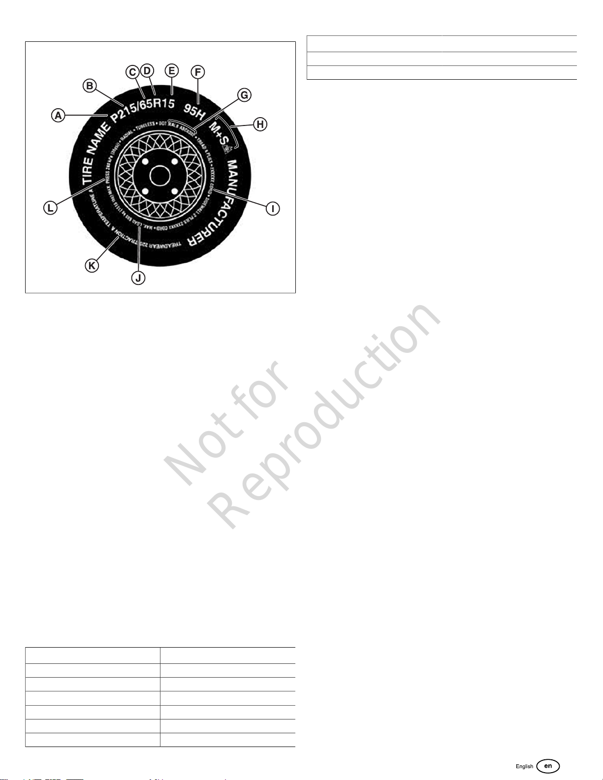
Information on Passenger Vehicle Tires
Please refer to Figure 1 and the information following.
Not for
Reproduction
11
1
A- 'P' indicates the tire is for passenger vehicles.
B- This three-digit number gives the width in millimeters of the
tire from sidewall edge to sidewall edge. In general, the larger
the number, the wider the tire.
C- This two-digit number, known as the aspect ratio, gives the
tire's ratio of height to width. Numbers of 70 or lower indicate
a short sidewall for improved steering response and better
overall handling on dry pavement.
D- "R" stands for radial. Radial ply construction of tires has
been the industry standard for the past 20 years.
E- This two-digit number is the wheel or rim diameter in
inches. If you change your wheel size, you will have to
purchase new tires to match the new wheel diameter.
F-
(Number) This two- or three-digit number is the tire's load
index. It is a measurement of how much weight each tire
can support. You may find this information in your owner's
manual. If not, contact a local tire dealer. NOTICE: You may
not find this information on all tires because it is not required
by law.
(Letter) The speed rating denotes the speed at which a tire
is designed to be driven for extended periods of time. The
ratings range from 99 miles per hour (mph) to 186 mph.
These ratings are listed below. NOTICE: You may not find
this information on all tires because it is not required by law.
Letter Rating Speed Rating
Q 99 mph
R 106 mph
S 112 mph
T 118 mph
U 124 mph
H 130 mph
Letter Rating Speed Rating
V 168 mph*
Y 186 mph*
* For tires with a maximum speed capability over 149
mph, tire manufacturers sometimes use the letters ZR. For
those with a maximum speed capability over 186 mph, tire
manufacturers always use the letters ZR.
G- U.S. DOT Tire Identification Number. This begins with
the letters "DOT" and indicates that the tire meets all federal
standards. The next two numbers or letters are the plant
code where it was manufactured, and the last four numbers
represent the week and year the tire was built. For example,
the numbers 3197 means the 31st week of 1997. The other
numbers are marketing codes used at the manufacturer's
discretion. This information is used to contact consumers if a
tire defect requires a recall.
H- The "M+S" or "M/S" indicates that the tire has some mud
and snow capability. Most radial tires have these markings;
hence, they have some mud and snow capability.
I- Tire Ply Composition and Materials Used. The number of
plies indicates the number of layers of rubber-coated fabric
in the tire. In general, the greater the number of plies, the
more weight a tire can support. Tire manufacturers also must
indicate the materials in the tire, which include steel, nylon,
polyester, and others.
J- Maximum Load Rating. This number indicates the
maximum load in kilograms and pounds that can be carried
by the tire.
K- Maximum Permissible Inflation Pressure. This number is
the greatest amount of air pressure that should ever be put in
the tire under normal driving conditions.
UNIFORM TIRE QUALITY GRADING (UTQGS)
Quality grades can be found where applicable on the tire
sidewall between tread shoulder and maximum section
width.For example:
TREADWEAR 200 TRACTION AA
TEMPERATURE A
All Passenger Car Tires Must Conform to Federal Safety
Requirements in Addition to These Grades
TREADWEAR
The treadwear grade is a comparative rating based on the
wear rate of the tire when tested under controlled conditions
on a specified government test course. For example, a tire
graded 150 would wear one and one-half (1-1⁄2) times as well
on the government course as a tire graded 100. The relative
performance of tires depends upon the actual conditions of
their use, however, and may depart significantly from the
norm due to variations in driving habits, service practices and
differences in road characteristics and climate.
TRACTION
The traction grades, from highest to lowest, are AA, A, B,
and C. Those grades represent the tire’s ability to stop on
Not for
Reproduction

12 www.allmand.com
wet pavement as measured under controlled conditions on
specified government test surfaces of asphalt and concrete.
A tire marked C may have poor traction performance.
Warning: The traction grade assigned to this tire is based on
straight-ahead braking traction tests, and does not include
acceleration, cornering, hydroplaning, or peak traction
characteristics.
TEMPERATURE
The temperature grades are A (the highest), B, and C,
representing the tire’s resistance to the generation of heat
and its ability to dissipate heat when tested under controlled
conditions on a specified indoor laboratory test wheel.
Sustained high temperature can cause the material of the tire
to degenerate and reduce tire life, and excessive temperature
can lead to sudden tire failure.The grade C corresponds to
a level of performance which all passenger car tires must
meet under the Federal Motor Safety Standard No. 109.
Grades B and A represent higher levels of performance on
the laboratory test wheel than the minimum required by law.
Warning: The temperature grade for this tire is established for
a tire that is properly inflated and not overloaded. Excessive
speed, underinflation, or excessive loading, either separately
or in combination, can cause heat buildup and possible tire
failure.
Additional Information on Light Truck Tires
Tires for light trucks have other markings besides those found
on the sidewalls of passenger tires. See Figure 2 and the
information following.
2
A- The “LT” indicates the tire is for light trucks.An “ST” is an
indication the tire is for trailer use only.
B- Load Range. This information identifies the tire’s load-
carrying capabilities and its inflation limits.
C- Maximum Load Dual. This information indicates the
maximum load and tire pressure when the tire is used as a
dual, that is, when four tires are put on each rear axle (a total
of six or more tires on the vehicle).*
D- The "M+S" or "M/S" indicates that the tire has some mud
and snow capability. Most radial tires have these markings;
hence, they have some mud and snow capability.
E- This information indicates the maximum load and tire
pressure when the tire is used as a single.*
*Maximum load is presented in kilograms and pounds (kg/
lbs). Maximum tire pressure is presented in kilopascals and
pounds per square inch (kPa/psi) for when the tire is cold.
Tire Safety Tips
Preventing Tire Damage
• Slow down if you have to go over a pothole or other
object in the road.
• Do not run over curbs of foreign objects in the roadway,
and try not to strike the curb when parking.
Tire Safety Checklist
• Check tire pressure regularly (at least once a month),
including the spare.
• Inspect tires for cracks, foreign objects, uneven wear
patterns on the tread, or other signs of wear or trauma.
• Remove bits of glass and foreign objects wedged in the
tread.
• Make sure your tire valves have valve caps.
• Check tire pressure before going on a long trip.
• Do not overload your vehicle. Check the tire information
placard or owner’s manual for the maximum
recommended load for the vehicle.
Features and Controls
Compare Figures 3 through 7 with the tables following.
Unit (from left front)
3
Ref Description
AUpper Storage Compartment Door
BLower Storage Compartment Door
CLunette Ring
DBulldog Hitch
ESafety Chains (2)
Not for
Reproduction

13
Ref Description
FTongue Jack
GHeater Unit Access Door
HHeater Fuel Tank Cap (multi-tank
models only)
IEngine Fuel Tank Cap (engine and
heaters for single-tank models)
JGround Lug
KControl Panel
Unit (from right rear)
4
Ref Description
AChimney (2)
BLifting Eye
CEngine Air Exhaust
DEngine Compartment Door
ETaillight (2)
FLicense Plate Light
GEngine Oil Drain
HFluid Containment Drain (2)
IHeater Air Intake (2)
JHeater Air Outlet (2)
Engine Compartment
5
Ref Description
AMain Circuit Breaker
BBattery
CGenerator
DEngine
ECoolant Overflow
Control Panel
6
Ref Description
AControl Panel Door
BEngine Fuel Tank Gauge (engine
and heaters for single-tank models)
CHeater Fuel Tank Gauge (2 - multi-
tank models only)
DEngine Control Panel ON / OFF
Switch
EDeep Sea Engine Control Module
FHeater Control Module
GRemote Thermostat Receptacle (2)
Heater Unit
Not for
Reproduction

14 www.allmand.com
7
Ref Description
AHeater Fan
BHeater Fuel / Water Separator
CBurner
DBurner Reset
EFuel Valve
FDamper
GHigh Temperature Reset
Transport
Before Transporting
1. Make sure that all manuals are in the manual storage
container.
2. Make sure that you can read the safety decals, and that
they are in their correct locations. See Safety Decals.
3. Inspect the heater trailer components:
A. Tongue Jack. With the heater trailer tongue safely
supported, make sure that the tongue jack operates
correctly. Make sure that the tongue jack can be
locked in the transport and operating position. See
Operate the Tongue Jack.
B. Trailer Coupler / Lunette Eye. Make sure that the
trailer coupler operates correctly, and that the
trailer coupler / lunette eye is attached to the heater
trailer tongue. See Use the Trailer Coupler and
Combination Trailer Coupler and Lunette Eye.
C. Safety Chains. Make sure that the safety chains are
attached to the heater trailer tongue, and that they
are not damaged. Replace damaged safety chains.
D. Trailer Lighting. Make sure that the trailer lighting
wiring and connector are not damaged. Repair or
replace damaged wiring or connector.
E. Break-Away Trailer Brake System. Make sure that
the break-away trailer brake system is fully charged
and that the pin is installed.
F. Tires. Inspect the condition and inflation pressure of
the tires. Replace worn or damaged tires. Adjust the
inflation pressure as needed.
4. Make sure that the grounding lug is clean and not
damaged.
5. Inspect the engine oil level and add oil as needed. See
Engine Oil.
6. Inspect the engine coolant level in the coolant overflow
bottle. It should be at least 1/3 full. Add coolant as
needed. See Engine Coolant.
7. Inspect the air filter for damage. Replace a damaged air
filter.
8. Make sure that the battery is connected and fully
charged. See Maintain the Battery.
9. Add fuel to the fuel tank(s) as needed. See Fuel the
Heater Trailer.
10. Make sure that the fuel shut-off valve for each heater unit
is in the OPEN position.
11. Make sure that the engine starts and runs correctly. See
Start the Engine. Also see the engine operator's manual.
12. Make sure that the heater units operate correctly. See
Operate the Heater Unit.
13. Make sure that the correct ducting is in the storage
compartment.
14. Make sure that all the covers and doors on the unit are
closed and locked.
Prepare the Unit for Towing
WARNING
Towing a trailer with an underrated tow vehicle or an
underrated trailer hitch could result in death or serious
injury. Always use a tow vehicle and trailer hitch that exceed
the Gross Vehicle Weight Rating (GWVR) of the heater
trailer.
1. See the owner's manual of the tow vehicle and trailer
hitch for the maximum rated towing capacity. Make sure
that the tow vehicle and trailer hitch are rated to tow the
heater trailer. See Heater Trailer Weight for information
on the heater trailer weight.
2. Make sure that the lighting connector on thetow
vehiclewill connect with the lighting connector on the
heater trailer. Also make sure that the auxiliary power
wire on the tow vehicle is connected and has power to
operate the break-away brake system.
3. The heater trailer has a 2" bulldog coupler and a 3"
lunette eye. Make sure that the tow vehicle has the
correct trailer hitch for either of those two towing options.
See Combination Bulldog Coupler and Lunette Eye
for information on changing between the bulldog coupler
and lunette eye.
Not for
Reproduction

15
Combination Bulldog Coupler and
Lunette Eye
The heater trailer has a reversible combination 2" bulldog
coupler and 3" lunette eye. See Specifications for the Gross
Vehicle Weight Rating (GVWR) for each.
To change between the bulldog coupler and lunette eye:
1. Inspect the tongue, bulldog coupler and lunette eye
for missing or damaged parts. Replace any part that is
missing or damaged.
2. Remove the twolock nuts (B, Figure 8) andhex head
bolts (A)fastening the combination bulldog coupler and
lunette eye to the heater trailer tongue. Discard the lock
nuts.
3. Turn the combination bulldog coupler and lunette eye to
match the trailer hitch on the tow vehicle.
4. Fasten the combination bulldog coupler and lunette eye
to the heater trailer tongue with the two hex head bolts
removed in Step 2 and two new lock nuts. Use the set of
mounting holes (C or D, Figure 8) that will work best for
your tow vehicle. Tighten the lock nuts.
WARNING
Use new lock nuts to fasten the combination bulldog coupler
and lunette eye to the heater trailer tongue. Failure to do so
could result in death or serious injury.
8
Connect the Heater Trailer to the Tow
Vehicle
1. Put wheel chocks against the front and rear of the wheels
on both sides of the heater trailer.
2. Use the tongue jack to lift the bulldog coupler or lunette
eye above the hitch ball or pintle hook on the tow vehicle.
See Use the Tongue Jack.
3. Move the tow vehicle so that the hitch ball or pintle hook
is below the bulldog coupler or lunette eye.
4. Use the tongue jack to lower the bulldog coupler or
lunette eye onto the hitch ball or pintle hook.
5. Lock the bulldog coupler or pintle hook. See Use the
Bulldog Coupler or Use a Pintle Hook.
6. Attach the safety chains (A, Figure 9) to the hitch frame
on the tow vehicle. Make sure that the chains cross each
other below the trailer tongue. Adjust the length of the
chains so that they do not touch the ground, but so that
the tow vehicle can turn freely.
7. Connect the lighting harness from the heater trailer to
the harness on the tow vehicle (B, Figure 9). Make sure
that the harness has enough length so that it does not
disconnect when turning, but does not touch the ground.
8. Connect the cable from the break-away brake switch to
the tow vehicle. See Break-Away Brake System.
9. Retract the tongue jack fully, and move it into the
transport position. See Use the Tongue Jack.
10. Remove the wheel chocks.
9
Use the Tongue Jack
Use the tongue jack(C, Figure )to hold up the trailer tongue
and to adjust the heater trailer so that it is level.
Extend or Retract the Tongue Jack
1. Turn the tongue jack handle (A, Figure 10) clockwise to
extend the tongue jack and lift the trailer tongue.
Not for
Reproduction
16 www.allmand.com
2. Turn the tongue jack handle counterclockwise to retract
the tongue jack and lower the trailer tongue.
Move the Tongue Jack into the Operating or Transport
Position
1. Use an approved means to safely hold up the trailer
tongue.
WARNING
Failure to use an approved means to hold up the trailer
tongue could result in death or serious injury.
2. Fully retract the tongue jack. See Extend or Retract the
Tongue Jack.
3. Remove the tongue jack lock pin (B, Figure 10).
4. Turn the tongue jackto the operating position (D, Figure
10) or the transport position (E).
5. Fully install the tongue jack lock pin.
WARNING
Failure to fully install the tongue jack lock pin could result in
death or serious injury.
10
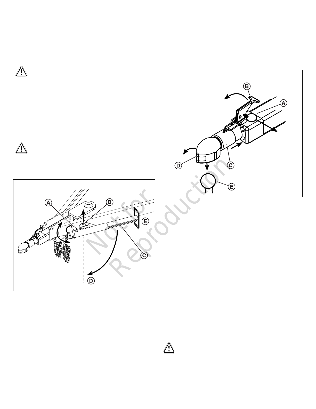
Use the Bulldog Coupler
Connect
1. Open the coupler: Remove the pin (A, Figure 11) from the
latch (B) and lift the latch. Make sure that the coupler cap
(D) is open and holds the collar (C) back.
2. Use the tongue jack to lower the trailer onto the hitch ball
(E, Figure 11).Examine the hitch ball to make sure that it
is fully seated in the coupler.
3. Carefully close the coupler cap, then lower the latch.
Make sure that the collar, which is spring-loaded, locks
the coupler cap.
4. Install the pin into the latch. Do not tow the trailer without
the pin in the latch.
5. Do a careful check of the coupler to make sure that it is
attached to the ball hitch.
Disconnect
1. Remove the pin from the latch and lift the latch. Make
sure that the coupler is open and holds the collar back.
2. Use the tongue jack to lift the coupler above the hitch ball.
11
Use a Pintle Hook
Use a pintle hook that meets the requirements of SAE J847
for a Gross Vehicle Weight Rating (GVWR) of not less than
6000 lbs (2722 kg).
Refer to the pintle hook manufacturer's instructions for
connecting and disconnecting the lunette eye.
Break-Away Brake System
The trailer has electric brakes, and a break-away brake
system that automatically stops the trailer if it disconnects
from the tow vehicle.
The break-away brake system has a power box with a 12-
volt battery, a break-away switch, and a break-away pin and
cable.
The auxiliary power wire on the tow vehicle must be
connected and have power for the system to work.
Do not use the break-away brake system as a parking brake.
Check the Break-Away Brake System
WARNING
Towing the trailer with the break-away brake system not
fully charged could result in death or serious injury. Make
sure that the break-away brake system is fully charged
before towing the trailer.
1. Before connecting the trailer to the tow vehicle, push the
TEST button on the power box. A green light means the
Not for
Reproduction

17
battery is fully charged. A red light means the battery
needs charging.
2. If the battery needs charging, connect the trailer lighting
harness to the tow vehicle harness. An amber light
means the battery is charging.
3. When the battery is fully charged, pull the break-away
cable until the pin disconnects from the break-away
switch. The electric brakes should engage.
Connect the Break-Away Brake Switch Cable to the Tow
Vehicle
1. Pull the break-away pin and cable (A, Figure 12) from the
break-away switch (B).
NOTICE Components may be different from those shown.
2. Put the pin through the safety chain pocket on the tow
vehicle (C, Figure 12), then through the loop on the end
of the cable (D). Use the safety chain pocket that is on
the same side as the break-away switch, and keep clear
of the hitch components.
3. Install the pin into the break-away switch.
12
Trailer Weight
WARNING
Towing the trailer when it is loaded above the Gross Vehicle
Weight Rating (GVWR) shown on the trailer serial plate
could result in death or serious injury. Keep the GVWR at or
below what is shown on the serial plate.
The trailer is an SAE Class 4 trailer, with a Gross Vehicle
Weight Rating (GVWR) as shown on the trailer serial plate
and in the Specifications section of this manual.
When putting tools or equipment on the trailer, do not go
above the GVWR.
Tow the Trailer
WARNING
Towing the trailer at unsafe speeds could result in death
or serious injury. Keep a safe towing speed for road
conditions.
The maximum rated highway towing speed for this trailer is
65 mph (105 km/h). Refer to your state, province or local laws
for maximum legal towing speeds.
When towing the trailer off-highway or on rough terrain, the
maximum towing speed is 20 mph (32 km/h). Slower speeds
may be necessary for very rough terrain.
Shut down the engine and all other components before
towing the trailer.
Disconnect the Heater Trailer from the
Tow Vehicle
1. See Choose the Work Site in the Operation section.
2. Move the heater trailer with the tow vehicle so that the
air outlet side is pointed in the direction of the area to be
heated. Do not move the heater trailer by hand.
WARNING
Trying to move the heater trailer by hand could result in
death or serious injury. Use the tow vehicle to move the
heater trailer.
3. Put wheel chocks against the front and rear of each
wheel.
4. Disconnect the lighting harness from the tow vehicle
harness.
5. Set the tongue jack in the operating position. See Use
the Tongue Jack. Extend the tongue jack until it touches
the ground.
6. Disconnect the bulldog coupler or pintle hook. See Use
the Bulldog Coupler or Use a Pintle Hook.
7. Use the tongue jack to lift the trailer tongue above the
hitch ball or pintle ring on the tow vehicle.
8. Disconnect the safety chains from the tow vehicle.
9. Disconnect the break-away cable from the tow vehicle.
10. Move the tow vehicle away from the heater trailer.
Lift the Heater Trailer
WARNING
Lifting the heater trailer with a lifting device that is damaged
or not rated for the weight of the heater trailer could result in
death or serious injury. Make sure that the lifting device is
rated for the weight of the heater trailer and is not damaged.
Not for
Reproduction

18 www.allmand.com
WARNING
Standing or walking below the heater trailer while it is lifted
could result in death or serious injury. Keep yourself and
others away from the area below and around the heater
trailer while it is lifted.
The heater trailer has a lifting eye at the top. See Trailer
Weight for the weight of the heater trailer.Use only the lifting
eye when lifting the heater trailer.
Do not add weight to the heater trailer when lifting.
Do not keep the heater trailer lifted for long periods of time.
The heater trailer does not have forklift pockets. Do not try to
lift the heater trailer with a forklift.
Operation
Choose the Work Site
It is the operator's responsibility to make sure that the heater
trailer is safely and correctly set up at the work site. Obey the
rules and instructions for the work site when setting up the
heater trailer.
Look for the following when choosing the work site:
Hard Level Surface
Set the heater trailer on a hard level surface that will hold the
weight of the trailer and the tongue jack. Make sure that the
surface does not have an incline of more than 2.5% (1.4°) in
any direction.
Safe Distance from Flammable Materials
Keep theheater trailer the following distances away from
flammable materials:
• Air inlet and outlet side - at least 8 ft (2,5 m)
• Top - at least 5 ft (1,5 m)
Sufficient Airflow
WARNING
Operating the heater trailer in a closed space could result in
death or serious injury. Operate the heater trailer in an area
where there is sufficient airflow.
The engine and heater units produce carbon monoxide, a
colorless odorless gas that could cause death. Make sure that
the heater trailer is set up in an area where there is sufficient
airflow. Do not set up or operate the heater trailer in a closed
space.
The odor of diesel fuel at the air outlet is not an indication of
carbon monoxide.
Add Fuel to the Heater Trailer
WARNING
Adding fuel to the heater trailer with the engine or heater
units operating could cause fire resulting in death or serious
injury. Shut down the engine and heater units before adding
fuel.
The heater trailer has two fuel tank options:
• Three (3) separate fuel tanks, one for the engine (A,
Figure 13) and one for each heater unit (B). The fuel tank
caps are located on the left side of the heater trailer.Fill
the engine fuel tank with No. 1 Ultra Low Sulfur Diesel
(ULSD). Fill the heater unit fuel tanks with either No. 1
Ultra Low Sulfur Diesel (ULSD) or Kerosene.
• One (1) single fuel tank(A, Figure 13)for the engine and
the heater units.Fill the fuel tank with No. 1 Ultra Low
Sulfur Diesel (ULSD).
NOTICE Using engine fuels other than what is
recommended could cause damage to the engine or its
emission control system and void the engine manufacturer's
warranty. Read and obey the engine manufacturer's fuel
recommendations.
13
Prepare to Operate the Heater Trailer
1. Put wheel chocks against the front and rear of each
wheel.
2. Use the tongue jack to adjust the heater trailer so that
it is level front to rear. See Use the Tongue Jack in
Transport.
3. Open the engine compartment door and do a check of
the:
A. Engine oil. Remove the dipstick from the engine and
examine the engine oil level. Keep the engine oil level
between the FULL and ADD marks on the dipstick.
Add as needed. See Engine Oil in Maintenance.
B. Engine coolant. Keep the engine coolant recovery
bottle at least 1/3 full. Also remove the radiator cap
Not for
Reproduction

19
and examine the coolant level. Add as needed. See
Engine Coolant in Maintenance.
WARNING
Release of hot coolant under pressure could result in death
or serious injury. Use caution when removing the radiator
cap. Wear eye protection and heat resistant gloves.
C. Main breaker. Turn the main breaker to the ON
position. See Features and Controls.
4. Add fuel. Do a check of the fuel gauge(s) and add fuel as
needed. See Add Fuel to the Heater Trailer.
5. Open the heater unit access doors, and turn the heater
unit fuel valves to the OPEN position (parallel with the
fuel line). See Features and Controls.
6. Open the heater outlet doors (A, Figure 14). Install the
correct ducting to the heater outlet cones. See Install the
Ducting.
NOTICE The heater units will not operate unless the
heater outlet doors are open.
7. Remove the air inlet covers (B, Figure 14). Push in the
spring pin on the side of the cover to remove. Ducting can
be installed to the air inlets, but it is not necessary.
NOTICE Failure to remove the air inlet covers could cause
damage to the heater units. Make sure that you remove the
air inlet covers.
14
Install the Ducting
Heater Outlet
Each heater outlet can have the following diameter ducting
sizes:
• Two 12 inch (305 mm)
• Single 16 inch (406 mm)
• Single 20 inch (508 mm)
See your authorized dealer.
Strap and Clamp Ducting
1. Install the ducting hose (A, Figure 15) onto the heater
outlet ring.
2. Make sure that the end of the ducting hose is past the
bead in the center of the heater outlet ring (B, Figure 15).
3. Pull the strap clamp tight (C, Figure 15).
15
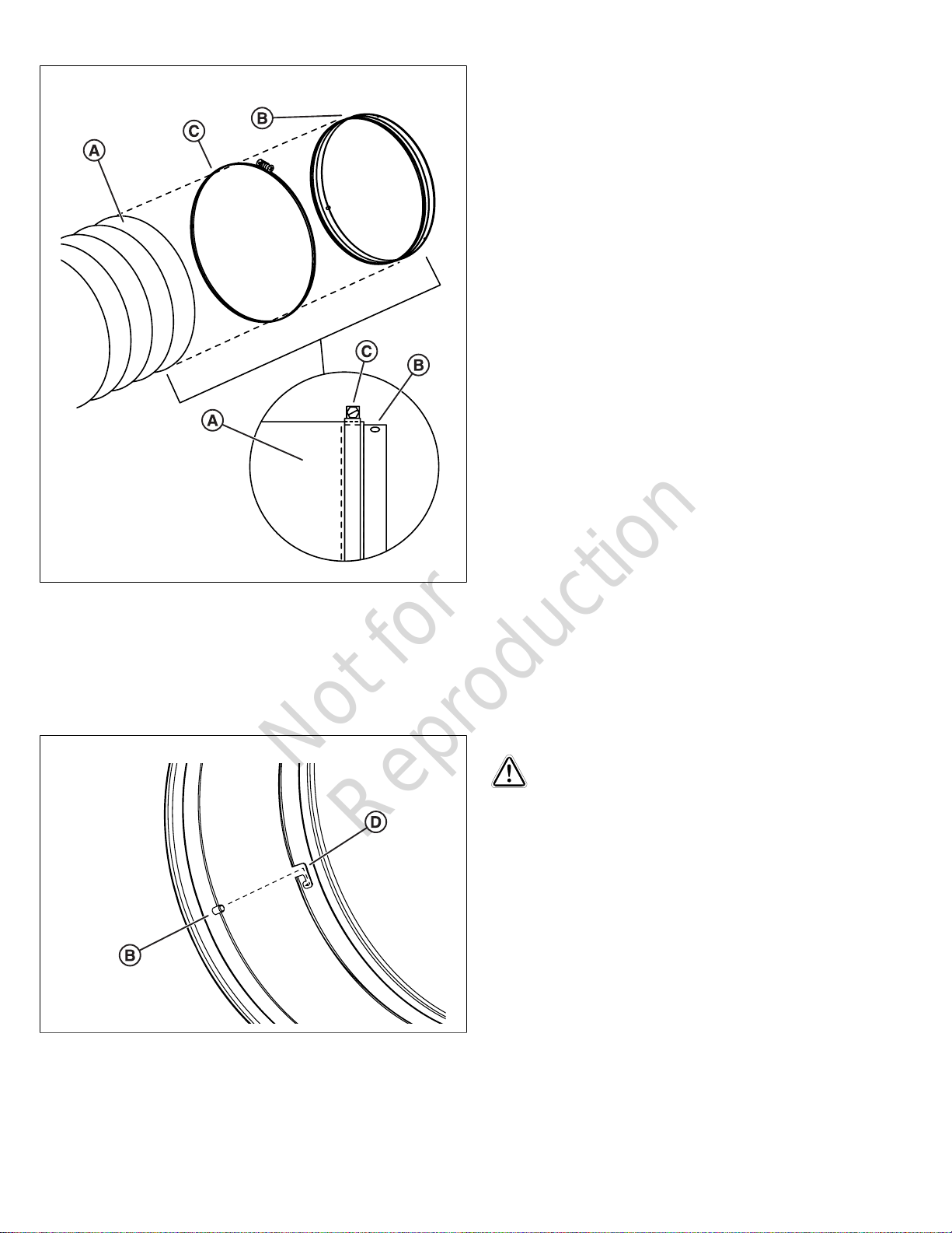
Slip-Lock Ducting
1. Install the worm drive clamp (C, Figure 16) onto the end
of the ducting hose (A).
2. Install the slip-lock connecting band (B, Figure 16) into
the same end of the ducting hose. Stop at the bead in the
center of the connecting band. Make sure that the pins
are on the outer part of the band.
3. Tighten the worm drive clamp.
Not for
Reproduction
20 www.allmand.com
16
4. Install the ducting hose assembly onto the heater outlet
ring:
A. Align the pins on the connecting band (B, Figure 17)
with the J-slots on the heater outlet ring (D).
B. Push and turn the connecting band to lock the
ducting hose assembly in place.
17
After the ducting is installed, adjust the routing of the ducting
as necessary for your jobsite.
Air Inlet
Each air inlet can have 16" (406 mm) diameter ducting, but
it is not required. See Strap and Clamp Ducting and Slip-
Lock Ducting.
Operate the Engine
Start the Engine
1. Turn the engine control panel ON / OFF switch (D, Figure
6)to the ON position.
2. Push the ON button on the Deep Sea control module (E,
Figure 6) two times (2X).
Refer to the Deep Sea control module operator's manual and
engine operator's manual for further information.
Stop the Engine
1. Shut down the heater units. See Operate the Heater
Unit.
2. Push the OFF button on the Deep Sea control module.
3. Turn the engine control panel ON / OFF switch to the
OFF position.
Refer to the Deep Sea module operator's manual and engine
operator's manual for further information.
Block Heater
The engine has a frost plug style electric block heater, located
on the left side of the engine. Use a 3-prong, grounded
extension cord to connect the block heater to a 120-volt AC
power source.
Jump Start the Battery
Before you try to jump start the battery, make sure that
the battery cells are filled and the battery is not frozen or
damaged. Do not jump a frozen or damaged battery.
WARNING
Explosion Hazard
Trying to jump start a frozen or damaged battery could
result in death or serious injury. Do not try to jump start a
frozen or damaged battery.
1. Connect one end of the red jumper cable to the positive
(+) terminal on the booster vehicle battery. Then connect
the other end of the red jumper cable to the positive (+)
terminal on the heater trailer battery.
2. Connect one end of the black jumper cable to the
negative (-) terminal on the booster vehicle battery. Then
connect the other end of the black jumper cable to an
unpainted surface on the heater trailer engine.
3. Make sure that the jumper cables are not near any
moving parts of either engine.
4. Start the engine of the booster vehicle and let it operate
at idle for several minutes.
5. Start the engine of the heater trailer and let both engines
operate for several minutes.
Not for
Reproduction
Table of contents
Languages:
Other Allmand Heater manuals


Popular Heater manuals by other brands

Renkforce
Renkforce PTC-17 operating instructions

Hotass Saunas
Hotass Saunas ProHeat P300/KIP30W1 Installation and operation manual

Better Bathrooms
Better Bathrooms Sahara BeBa-27962 user manual

STIEBEL ELTRON
STIEBEL ELTRON CAES 500 Instructions for installation and use

DELTACALOR
DELTACALOR DROP Operation and installation manual

TECHWOOD
TECHWOOD TCG-1501 instruction manual


YATO
YATO YT-99500 Original instructions

Beko
Beko CLEARPOINT S040 TWC Control Instructions for installation and operation

Somogyi Elektronic
Somogyi Elektronic HOME FK 29 instruction manual

Adexa
Adexa PHW-3000R user manual

Tradesman
Tradesman K70 owner's manual

BN Thermic
BN Thermic System X XAS-45 instructions