Allmand ECLIPSE 2220/SE Series Product manual

1
OPERATOR’S AND PARTS MANUAL
2220/SE SERIES
FLASHING ARROWBOARD
ALLMAND BROS. INC
P.O. BOX 888
HOLDREGE, NE 68949
PHONE: 308/995-4495, 1-800/562-1373
ALLMAND FAX: 308/995-5887
ALLMAND PARTS FAX: 308/995-4883
ECLIPSE 2220/SE
ECLIPSE
For Parts and Updates visit Allmand on the Web at www.allmand.com

2

3
TABLE OF CONTENTS
ALLMAND 2200/SE ECLIPSE
Table of Contents Page 3
Description and Features Page 4
Safety and Precautions Page 5
Set-up/Operating Instructions Page 6
Trailer Alignment (illustration) Page 7
Safety and Warning Decals Page 8
Winch Operating Instructions Page 9
Periodic Maintenance Page 10
Array Maintenance Page 10
Battery Maintenance Page 11
Troubleshooting Page 12
Controller (illustration) Page 13
Controller Features and Operation Page 14
APF Flashing Array Display Sequence Illustrations Page 15
Allmand Eclipse 2220/SE Halogen Lamp Descriptions Page 16
Allmand Eclipse 2220/SE LED Lamp Descriptions Page 16
Wiring Diagrams Page 17
Serial Number Plate Location Page 18
Parts and Accessories Page 19

4
ALLMAND ECLIPSE 2220/SE SERIES SOLAR ASSIST ARROWBOARD
DESCRIPTION AND FEATURES
The ALLMAND ECLIPSE 2220/SE SERIES solar assist arrowboard uses two, three or four
12V DC 8D deep cycle batteries, providing a nominal 12V DC to the operating system. The
battery enclosure is lockable, ventilated and designed to protect the batteries from theft or
vandalism. The location of the enclosure allows for easy maintenance or replacement of the
battery bank. An electronic control system protects the batteries from overcharging and gas-
sing. The Low Voltage Disconnect (LVD) system protects the battery from excessive dis-
charge which can result in premature battery failure.
Solar charging is accomplished by a 50w, 75w, or 100w class 12V DC single crystalline
photovoltaic array located above the sign panel. This provides maximum exposure of the array
to the sun. The array location minimizes vandalism or theft. The array constantly charges the
batteries when exposed to the sun. An optional ALLMAND ECLIPSE battery charger, specifi-
cally designed for this unit, allows the batteries to be recharged using standard 115V AC line
current.
The ALLMAND ECLIPSE 2220/SE SERIES features the Allmand Eclipse LED Lamp con-
sisting of individual ORANGE/AMBER LEDs per lamp. Each LED is situated on a printed
circuit board behind an individual Fresnel lens element. If an individual LED burns out, the
entire lamp does not go out. This results in greater safety as the sign will still show a complete
display even if several individual LEDs in a number of lamps are not functioning. The LED
lamp easily interchanges with halogen lamps, allowing older halogen equipped boards to be
re-fitted with LED lamps. It is not recommended, however, that LED and halogen lamps be
mixed in the same board.
The LED lamp has approximately 1/5 of the power requirement of the ALLMAND halogen
lamp, resulting in much longer run time between recharges. With the LED lamp, the display is
more defined, resulting in greater legibility distances (greater than one mile, which exceeds
MUTCD requirements). The ALLMAND LED lamp carries a 5-year limited warranty from the
manufacturer against defects in materials and workmanship.
Also available is our proven modular PAR-46 high visibility/high efficiency halogen lamp. The
lamp life is over three times that of a standard 4412-A lamp . The lamp housing/reflector and
Lexan lens provide an extremely durable and damage-resistant assembly. This lamp assembly
easily meets or exceeds the MUTCD (Section 6E-9) one mile visibility specification.
The ALLMAND ECLIPSE 2220/SE SERIES CONTROLLER is mounted directly on the sign
panel to minimize electrical connections and exposed wiring. This feature, along with the
lockable cover, also makes malicious mischief or vandalism less likely. This unit is a high-
reliability solid state component featuring state of the art electronics and engineering. Lamp
dimming during night time hours is accomplished via the ALLMAND ECLIPSE SUNTRAK
system which automatically varies the lamp intensity relative to ambient light levels.

5
The trailer consists of a formed 10 GA steel deck with crossmembers and an integral battery
compartment with lockable steel cover. Four steel uprights welded to the deck support the sign
panel for operation and transportation. A positive mechanical lock secures the sign in both
operating and towing positions. The tongue is constructed of 3" tubing and has a heavy-duty
combination 3" diameter pintle ring and 2" ball coupler. A folding screw jack is mounted to the
tongue immediately behind the pintle eye. Four adjustable corner stands (one at each corner of
the trailer) stabilize the trailer when in operation. They are constructed of 1-3/4" Telespar tubing
complete with footpads, locking pins, and clips. The trailer rides on a 1500 lb. tube-type leaf
spring axle with 5-lug hubs and 13" 4-ply rated tires and wheels. Raising and lowering of the sign
panel is accomplished by a ratchet-type hand crank winch and pulley system with safety brake
clutch and a single 3/16" braided steel cable that will raise and lower the sign panel evenly. Flush
mounted stop, turn, and taillights with a 4-contact male end connector on the cable insures
towing safety. Color coding of the wiring is in accordance with SAE practice, (SAE J560A and
SAE J895). The trailer is finished in high-visibility Safety Or-
ange paint.
SAFETY AND PRECAUTIONS
A safe environment around the ALLMAND ECLIPSE 2220/SE
SERIES SOLAR ASSIST AROWBOARD is encouraged. The
following recommendations should be noted since the
ALLMAND ECLIPSE 2220/SE SERIES is typically used in
construction areas with greater traffic congestion, thereby
increasing the risk of accidents or injuries.
The sign panel should always be in travel position (lowered)
and secured using the attached lock pins when towing the
ALLMAND ECLIPSE 2220/SE SERIES at highway
speeds. Make sure that the hitch is properly engaged with
the towing vehicle and that the safety chains are properly
fastened and all jacks and/or jackstands are raised and
secured before towing. Also be certain that the taillights are
connected and working properly before towing the unit.
DESCRIPTION AND FEATURES
A low-voltage disconnect (LVD) system protects the batteries from damage if solar conditions fail
to adequately maintain a sufficient charge. This system features a red warning lamp which signals
low battery voltage and imminent shutdown of the system. This lamp is mounted on the rear of the
sign panel and is easily visible from the jobsite or roadway. If battery voltage becomes danger-
ously low, the sign panel display will revert to a 4-corner warning mode. At this time mainte-
nance personnel will need to either recharge the batteries or replace them with fully
charged units if necessary.

6
The trailer should be properly set up with the jack stabilizers, sand bags, etc. in position before
leaving the ALLMAND ECLIPSE 2220/SE SERIES deployed in the traffic control area. Periodi-
cally inspect the tongue, pins, safety chains, hitch, all nuts, bolts, cable clamps, wiring, etc. for
wear and repair or replace if necessary.
SAFETY NOTE/DISCLAIMER
ALLMAND BROS. INC. has taken precautions to ensure that the ALLMAND ECLIPSE
2220/SE SERIES is safe and reliable. ALLMAND BROS. INC., however, is not responsible
for any injuries, accidents or other mishaps as a result of the use or misuse of this or any other
ALLMAND product. It is the user’s responsibility to ensure that the manner in which the
ALLMAND ECLIPSE 2220/SE SERIES is used is consistent with safe practices and the user
is to understand that he/she is the only liable party.
SET-UP/OPERATING INSTRUCTIONS
The following is a step-by-step procedure for set-up and operation of the ALLMAND ECLIPSE
2220/SE SERIES SOLAR ASSIST ARROWBOARD.
NOTE: Before transporting the trailer to the jobsite, be certain that the batteries are fully charged
using the optional ALLMAND ECLIPSE charger or any commercially available minimum 50
amp battery charger designed to charge a deep-cycle battery bank of this size. Be certain that
the battery bank is charged completely, allowing the unit to operate as long as possible before
low-voltage shutdown occurs.
1. Block the wheels of the trailer first, then remove the trailer from the towing vehicle.
2. With the sign panel directed toward the traffic, level unit off the tires using the jacks and /or
jackstands.
CAUTION: For safe operation and maximum visibility, sight through the eyelets midway up the
right frame uprights to align the unit relative to the roadway and the horizon as illustrated on the
following page. Observe the operation of the machine from varying vantage points down the
roadway to ensure that maximum visibility is maintained throughout the controlled area.
Lift the controller cover and turn mode switch to desired mode. Turn power switch on and deter-
mine that the display that has been selected is the desired mode and that it is operating properly.
CAUTION: Always check for overhead obstructions before raising sign panel.
3. Remove sign panel spring pins and erect sign panel by cranking braking winch. See WINCH
OPERATING INSTRUCTIONS on page 8.
4. Insert spring pins into the trailer uprights to stabilize the sign.
5. Ensure that the display is operating correctly and is readable from an adequate distance
before leaving the worksite.
7
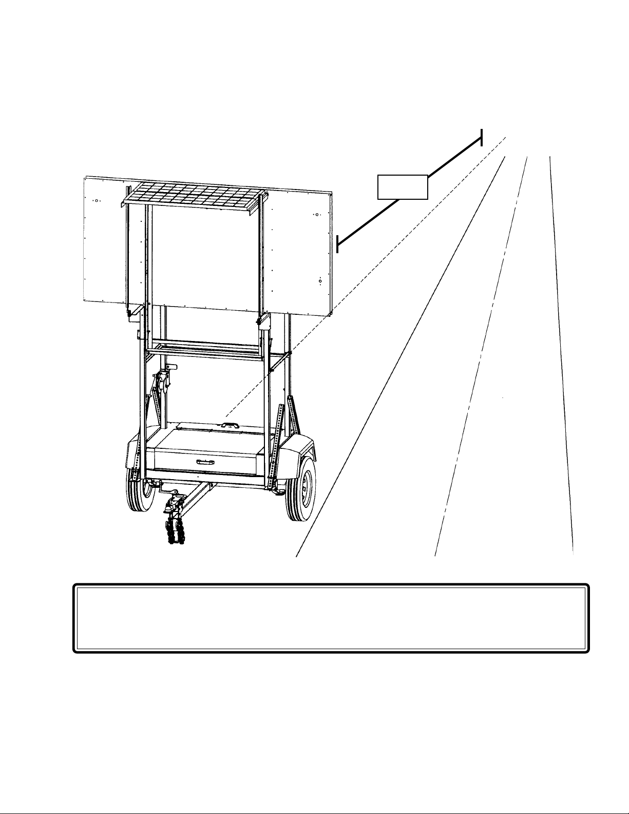
TRAILER ALIGNMENT ILLUSTRATION
CAUTION: For safe operation and maximum visibility, sight through the eyelets midway up the
right frame uprights to align the unit relative to the roadway and the horizon as illustrated above.
Observe the operation of the machine from varying vantage points down the roadway to ensure
that maximum visibility is maintained throughout the controlled area.
1 MILE

8
SAFETY AND WARNING DECALS
ALWAYS REPLACE ANY SAFETY AND INSTRUCTIONS DECALS THAT BECOME
DAMAGED, PAINTED OVER, OR OTHERWISE ILLEGIBLE!
Refer to the following representations of the safety warning decals used on the ALLMAND
ECLIPSE 2220/SE Series trailer to insure correct ordering if replacement becomes neces-
sary.

9
WINCH OPERATING INSTRUCTIONS
The winch is designed to lift load (“reel in”) when the crank is turned in a clockwise direction.
This action will produce a clicking sound. To lock load at any desired position, simply release
the hand crank. To lower load (“reel out”), turn the hand crank in a counter-clockwise direction.
To lock load in any desired position, turn handle crank clockwise until at least two clicks are
heard before releasing handle.
WARNING: Never exceed rated winch load. Excess load may cause premature failure and
could result in serious personal injury. This winch is rated at 1200 pounds with one layer of
cable on a 2-1/2" hub. Using more layers of cable increases the load on the winch.
CAUTION: Never apply load to winch with cable fully extended. Keep at least three full turns of
cable on the reel.
IMPORTANT: Sufficient load must be applied to the cable to overcome internal resistance
and operate brake properly. Otherwise, turning the hand crank counter-clockwise will only
remove the crank from the shaft as the reel will not turn. Minimum operating load requirement
for the DLB-1200 winch is 75 pounds.
NOT FOR MOVEMENT OF HUMAN BEINGS
WINCH LUBRICATION: This winch has been fully lubricated at the factory, but for continued
smooth performance and increased life, occasionally grease gears, reel shaft and handle
threads. An occasional drop of oil on drive shaft bearings is also recommended.
CAUTION: DO NOT OIL OR GREASE BRAKE MECHANISM

10
PERIODIC MAINTENANCE
The ALLMAND ECLIPSE 2220/SE SERIES SOLAR ASSIST ARROWBOARD has been
designed to minimize maintenance. However it will be necessary to inspect or test the follow-
ing areas on a periodic basis.
ARRAY MAINTENANCE
1. Clean solar panels.
2. Check solar panels and wiring.
3. Check wiring to ensure that there is no damage caused by normal use, wear and tear, road
vibration, etc.
BATTERY MAINTENANCE
4. Check water level on each cell of the batteries. Top off when necessary using only distilled
water.
5. Check battery condition . Charge when necessary or when not in use.
GENERAL MAINTENANCE
6. Check taillights to ensure proper operation. Also check tongue, safety chains and pins.
7. Check sign panel for proper lamp operation. Replace lamps when needed.
8. Check tires and wheel bearings.
9. Check all nuts and bolts for tightness.
ARRAYMAINTENANCE
Examine the entire array for the following:
Examine the top (photosensitive) surface of each module for cleanliness. Any visible accumu-
lation of dirt can impair energy production and should be removed. Use a soft cloth and either
plain water or a solution of mild detergent (such as dishwashing detergent) followed by a rinse
with plain water. Do not spray or direct a solid stream of water at the modules. No abrasive
material should be used in cleaning the modules. It is very important to note that water can
increase the chance of electrical shocks and burning. Care should be taken to use properly
insulated tools and rubber gloves when cleaning the modules.
Examine all electrical cabling. Make certain that connections are tight at the module junction
boxes, the controller, and the battery bank. Look for any signs of cable breaks and also for
damaged or missing insulation. If any worn or damaged wiring appears likely to interfere with
proper operation now or later, replace the damaged wire.

11
ARRAYMAINTENANCE (cont)
The array may be tested by using a voltmeter to check the voltage across the array (+) terminal
and array (-) terminal of the sign connector. Expose array to full sunlight. Using a voltmeter, check
open circuit voltage across the leads. The meter should indicate a voltage reading of 16-20V
DC.
Check all bolts and nuts. Tighten as needed.
BATTERYMAINTENANCE
Check the level of electrolyte in each battery cell. If necessary, add DISTILLED water to bring the
electrolyte up to the required level. A hydrometer may be used to test the condition of each
individual cell or a voltmeter may be used to test the condition of each individual battery.
Examine all battery terminals for signs of corrosion. If any terminal is corroded, disconnect the
battery cable. Clean the battery terminal and the connector on the cable with appropriate wire
brushes. Reconnect the cable to the battery terminal.
NOTE: Batteries must be recharged periodically using an AC battery charger to avoid over-
sulfating plates and impairment of battery performance.
If ALLMAND ECLIPSE 2220/SE Series supplied BATTERY CHARGER is not used, a charge
current of at least 50 amps must be provided to sufficiently charge batteries. Use extreme cau-
tion when using other than ALLMAND ECLIPSE 2220/SE Seriescharger to observe correct
battery polarity and also to avoid over-charging (“boiling”) of batteries.
CAUTION! Any battery is an infinite current source when the battery terminals are mo-
mentarily shorted which can lead to serious bodily injury or fire. Goggles and other
protective equipment should be worn to shield skin and eyes from battery acid.

12
TROUBLESHOOTING
The ALLMAND ECLIPSE 2220/SE SERIES SOLAR ASSIST ARROWBOARD is a highly reliable
and trouble free piece of equipment. However, should a rare problem occur, the following list of trouble-
shooting procedures will assist the operator in locating and correcting the source of the problem.
PROBLEM PROCEDURE
Display not functioning properly Check wiring, lamps and
or not functioning at all. connections. Replace lamp
elements or controller if necessary
Check batteries, re-charge or
replace if necessary.
No power to system. Check circuit breakers on
controller. Allow to automatically
reset if tripped. Check wiring.
Replace controller.
Operational time is less than desired. Check battery condition. Charge
batteries with heavy-duty AC charger. Use
hydrometer to ensure that batteries are
fully charged before putting unit into
service. (See BATTERY MAINTENANCE
section). Check solar panels. (See
ARRAY MAINTENANCE section.)
LVD lamp illuminated or system shut down. Charge batteries using properly sized AC
charger until voltmeter or hydrometer
indicates batteries are fully charged.
Batteries will not fully charge. Check battery condition. (See BATTERY
MAINTENANCE section.) Replace if
necessary.
NOTE: If it has been determined that the controller is defective it may be returned freight
prepaid to:
ECLIPSE ELECTRONIC REPAIR CENTER
1903 BARRETT DRIVE
TROY, MI 48084
PHONE: (248) 362-0544
Repair (or replacement at our option) and return will be done on a timely basis to minimize downtime.
Out-of-warranty units will be repaired on a time and materials basis, usually within two working days of
receipt. Be certain to specify the problem and include complete return information (including zip code,
phone/FAX numbers, contact person, purchase order number, etc.) with the failed unit.

13
CONTROLLER ILLUSTRATION
ALLMAND BROS., INC.
MODEL 2220/SE

14
CONTROLLER FEATURES AND OPERATION
1. MODE SWITCH: Selects display mode. Rotate switch to select desired display. 15 lamp
ALT display choices include:
LEFT ALTERNATING ARROW
LEFT SEQUENTIAL ARROW
RIGHT ALTERNATING ARROW
RIGHT SEQUENTIAL ARROW
LEFT/RIGHT ALTERNATING ARROW
LEFT/RIGHT SEQUENTIAL ARROW
ALTERNATING CAUTION BAR
4-CORNER WARNING
The optional 25 lamp APF display offers the following display choices in addition to the above:
LEFT SEQUENTIAL CHEVRON
RIGHT SEQUENTIAL CHEVRON
DOUBLE DIAMOND WARNING
SEQUENTIAL CAUTION BAR
2. ON-OFF SWITCH: Turns display on or off.
**CIRCUIT BREAKER: 6 amp auto-reset breaker protects controller from shorts in wiring or
lamps.
** PHOTOCELL: Located inside bottom frame channel of sign panel directly below controller.
ALLMAND ECLIPSE SUNTRAK system automatically varies lamp intensity relative to
ambient sunlight. Photocell location prevents false brightening of lamps by oncoming
vehicle lights.
** LOW VOLTAGE DISCONNECT WARNING LAMP (Not Shown):Located on sign panel
directly behind controller, flashes intermittently if battery voltage drops below 11.5 volts. At
this time maintenance personnel must take corrective action, as machine shut-down is
imminent. See TROUBLE SHOOTING and MAINTENANCE sections. (NOTE: Sign
panel will default to a 4-corner warning display if battery voltage falls below 10.5
volts.)
** POLARITY PROTECTION (Not Shown):Fuse located on P.C. board behind face panel
protects against damage to controller from reversed battery polarity.

15
APF FLASHING ARROW DISPLAYSEQUENCES
LEFT SEQUENTIAL CHEVRON
RIGHT FLASHING ARROW LEFT FLASHING ARROW
DOUBLE FLASHING ARROW RIGHT SEQUENTIAL ARROW
LEFT SEQUENTIAL ARROW FLASHING WARNING BAR
DOUBLE SEQUENTIAL ARROW DOUBLE DIAMOND WARNING
SEQUENTIAL WARNING BAR 4-CORNER WARNING DISPLAY
RIGHT SEQUENTIAL CHEVRON
16
ALLMAND ECLIPSE LAMPS
ALLMAND ECLIPSE 2220/SE SERIES LED LAMP ASSEMBLY
ALLMAND ECLIPSE LED LAMP DESCRIPTION AND FEATURES
•Each lamp has individual orange/amber LEDs, with each LED situated on a printed circuit
board behind an individual Fresnel lens element.
•The orange/amber color of the lamp display is more consistent with the color of the standard lamps
used in older diesel boards.
•If an individual LED burns out, the entire lamp does not go out. This results in greater safety as the
sign will still show a complete display, even if several individual LEDs in a number of lamps are not
functioning.
•The LED lamp easily interchanges with halogen lamps, allowing older halogen equipped boards to
be re-fitted with LED lamps. (However, it is not recommended that LED and Halogen lamps be
mixed in the same board.)
•The LED lamp has approximately 20% of the power requirement of the Eclipse halogen lamp, result
ing in much longer run time between recharges.
•LED lamp display is more defined, resulting in greater legibility distances (greater than ONE MILE,
which exceeds MUTCD requirements.)
•The LED lamp carries a 5-year limited warranty from the manufacturer against defects in materials
and workmanship.
LAMP VISOR ALLMAND LED LAMP
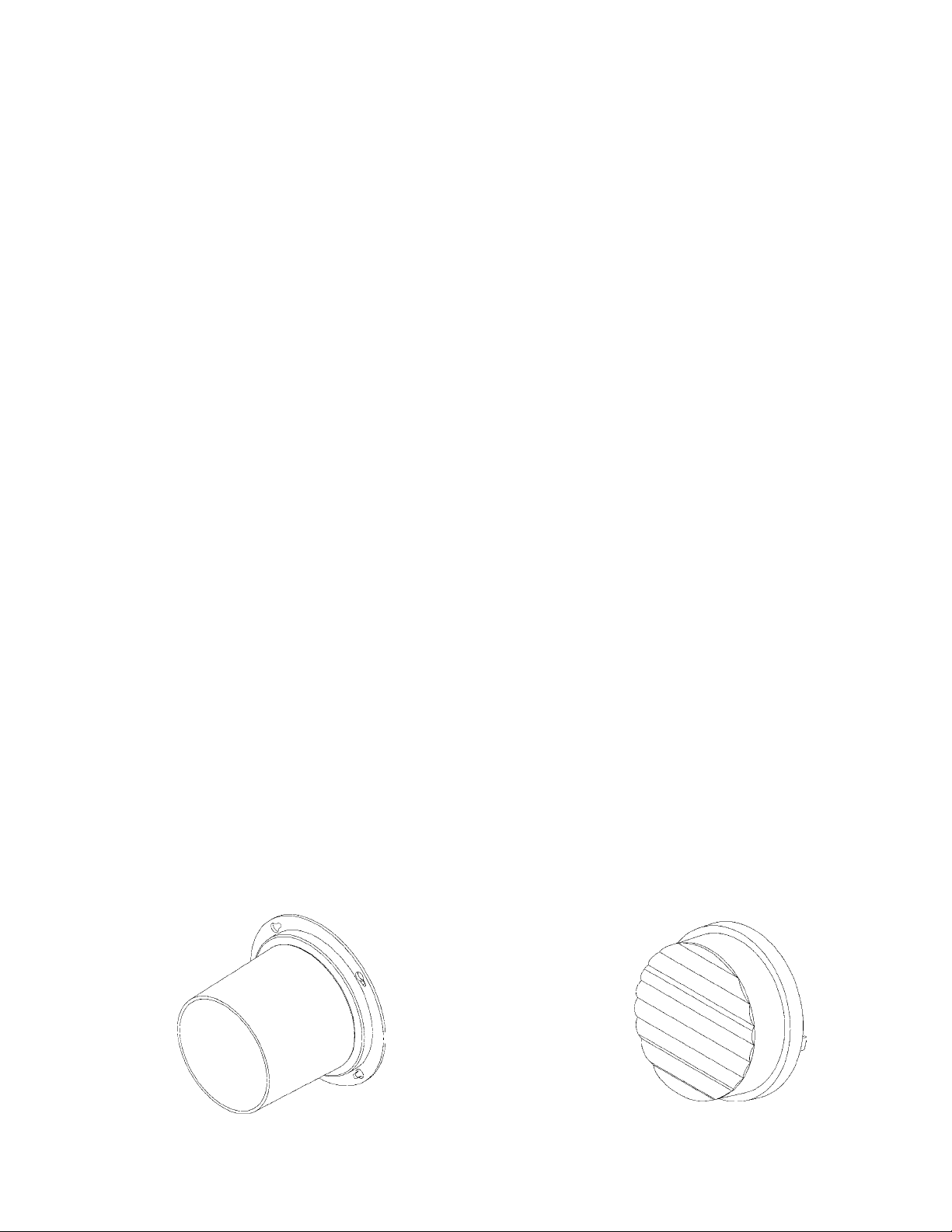
ALLMAND ECLIPSE HALOGEN LAMP DESCRIPTION AND FEATURES
1. LENS: Amber Lexan lens provides maximum durability and light transmittal.
2. HOUSING / REFLECTOR: Lexan housing provides greater durability than glass lamps.
Highly polished reflective surface features a 30° horizontal and 8° vertical beamspread for
maximum brightness and off-axis visibility.
3. LAMP ELEMENT: 12V DC 5W tungsten-halogen lamp element has three times the life
expectancy of a standard 4412A arrowboard replacement lamp.

17
ALLMAND ECLIPSE 2220/SE SERIES ARROWBOARD
SIGN PANEL WIRING DIAGRAM
APF (25-LAMP) SIGN ASSEMBLY
MOLEX CONNECTOR #1 MOLEX CONNECTOR #2
PIN# WIRE COLOR LAMP# PIN# WIRE COLOR LAMP#
1 BROWN 16 1 YELLOW 4
2 BLACK 9 2 PURPLE 10
3 RED 7 3 GRAY 3
4 YELLOW 12 4 BLUE 8
9 GREEN 6 8 BLACK 17*
10 BLUE 13 9 GREEN 2
11 GRAY 5 10 BLACK is
12 PURPLE 11 11 RED 1
12 BROWN 14
ALT (15-LAMP) SIGN ASSEMBLY
MOLEX CONNECTOR
PIN# WIRE COLOR LAMP #
1 YELLOW 14
2 GRAY 8
3 BLACK 2
4 RED 3,4
5 PURPLE 1
6 GREEN 5
7 BLUE 6
8 ORANGE 16
9 BROWN 13
10 PINK 7
SIGN PANEL LAMP NUMBERING CHART
(*) NOTE: LAMP #17 IS THE LOW VOLTAGE WARNING LAMP located on sign
behind controller.
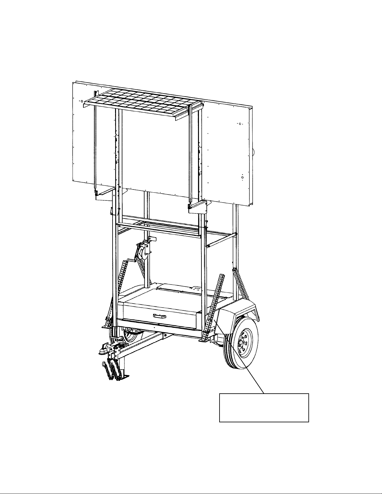
18 ALLMAND ECLIPSE 2220/SE SERIES P ARTS REFERENCE
MODEL SERIAL NUMBER PLATE LOCATION
ALLMAND
SERIAL NUMBER PLATE
LOCATED HERE

ALLMAND ECLIPSE 2220/SE SERIES PARTS REFERENCE 19
PARTS MANUAL
2220/SE SERIES
FLASHING ARROWBOARD
For Serial Number 0458AB02 and up
ALLMAND BROS. INC
P.O. BOX 888
HOLDREGE, NE 68949
PHONE: 308/995-4495, 1-800/562-1373
ALLMAND FAX: 308/995-5887
ALLMAND PARTS FAX: 308/995-4883
ECLIPSE 2220/SE
ECLIPSE

20 ALLMAND ECLIPSE 2220/SE SERIES P ARTS REFERENCE
Other manuals for ECLIPSE 2220/SE Series
1
Table of contents
Popular Safety Equipment manuals by other brands

Lanex
Lanex PB-20 instruction manual

SKYLOTEC
SKYLOTEC ANCHOR ROPES Instructions for use

Besto
Besto Buoyancy Aid 50N Instructions for use

TEUFELBERGER
TEUFELBERGER NODUS Manufacturer's information and instructions for use

Troy Lee Designs
Troy Lee Designs Tbone Product owners manual

Innova
Innova Xtirpa Instruction and safety manual

bolle SAFETY
bolle SAFETY B810 quick start guide

SHENZHEN FANHAI SANJIANG ELECTRONICS
SHENZHEN FANHAI SANJIANG ELECTRONICS A9060T instruction manual

Hiltron security
Hiltron security POWER8E Installation and use manual

Salewa
Salewa MTN SPIKE user manual

Hatco
Hatco B-950P installation guide

Sitec
Sitec TX MATIC operating manual


