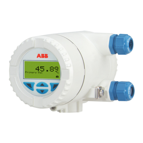
Allsensor P601 Series User manual

P601 HART Series
P601 Series HART Protocol
Pressure Transmitter Manual
HISCO Sensor Institute Inc.
#513~514 HausD biz 10, Seonyu-ro 3-gil Yeongdeungpo-gu, Seoul, Korea
Tel. : 82-2-2284-3737~9, Fax. : 82-2-2284-3740, www.allsensor.com

P601 HART Series
- 1 -
Contents
1. INTRODUCTION
2
2. SPECIFICATION
2
3. APPLICATION
3
4. DISPLAY
5
5. LOCAL ADJUSTMENT
7
6. NOTICE
11
7. ATTACHMENT : CONFIGURATION ADJUSTING SOFTWARE NOTE
12

P601 HART Series
- 2 -
1. INTRODUCTION
P601 with HART pressure transmitter is a SMART pressure measuring unit with 2-wire
analog signal outputs.
It has a good performance with digitally temperature compensation and non-linearity
correction, 4 1/2 digits LCD display with backlight, according with HART communication
protocol, It is available with long-distance operation.
The transmitter can be widely used in pressure measurements and industry process controls
system requiring BUS operation with HART protocol in the fields of petroleum, chemo-industry,
electric power and paper making etc, The unit can be compatible with the similar products
and suitable for applications requiring two wire analog signal transmission or long-distance
adjustment via HART handholding communicator.
Before using P601 transmitter, please read carefully this manual and operating accordingly.
2. SPECIFICATION
2.1 Specification
Input
Pressure Range
0.01 ... 100 MPa
Pressure reference
Gauge, Absolute, Vacuum and Compound
Over Pressure
1.5 x Rated Range or 110 MPa(Min. value is valid)
Media
The liquid or gas which is compatible with STS316L
Output
Output signal
4 ~ 20 mA with HART ® Protocol
Display
4 1/2 LCD Display with Backlight
Electrical specifications
Power supply
12 ~ 36V DC
Load resistance
Max. 500 Ω at 24V
Power ripple
≦500 mV P-P
Reverse polarity
Protected
Response time
(10~90%) ≦ 20 ms
Performance specifications
Accuracy
≦ ±0.25% FSO (±0.1% FSO Option)
Non-linearity
≦ ±0.100% FSO typical ±0.15% FSO
Hysteresis
≦ ±0.100% FSO typical ±0.10% FSO
Long term stability
≦ ±0.1% FSO over 1 Year
Ambient temperature
-20 ~ 40°C
Physical specifications
Process Connection
PT1/2"(Standard), PT1/4", PT3/8" Male Thread
Flange other connections available on request
Materials
Wetted Parts – welded STS316L
Housing – Aluminium Die-casting
Weight
Approx. 1.2kg
Option
Sanitary Diaphragm Seal or Remote Diaphragm Seal
Explosion proof
Ex d IIC T6 (15-GA2BO-0896)
(방호장치 의무안전인증고시 / 고용노동부고시 제 2013-54호, 개정일자 2013. 12. 18)
Enclosure
IP67

P601 HART Series
- 3 -
2.2 Dimension(mm)
Figure 2-1
3. APPLICATION
3.1 ELECTRICAL CONNECTION
The Supply/Signal terminal locates inside electronic housing. When making connection,
please open the transmitter cover firstly, the terminal’s definition see as the Figure 3-1, the
left terminal marked with "+" or "–" is for supply/signal.
Figure 3-1

P601 HART Series
- 4 -
Power is supplied by the signal wires. The Signal/Supply share one terminal(2 wires, no
additional supply wire). While you make connection, please take very carefully to make
correct connection: the "+"of Supply wires connecting with the "+" of Supply terminal
"+"on the left, signal current "-" out connecting the signal terminal "-" on the center.
The signal wire to use a shield cable or the twisted-pair couple wire can get the best
effect.
Please DO NOT let the signal wire share the same wire/cable allocation pipe or slot with
other equipment power supply wires, and the signal wire NOT close to the high-power
equipment. Using sealing element to seal the passing-hole after connecting the wires. In
case you can’t find a sealing element on site, please installing the transmitter with the
wires hole face down to prevent from entering water. The signal wire can be floating on
the ground or any one point in the signal loop grounded. The transmitter housing
grounded or not grounded are both okay.
The stability of supply voltage for transmitter is not strict, even if the voltage wave
around 1V, the influence on output signal is very small or can be ignored. The transmitter
is capacitive coupled grounded, while you are checking the insulation resistance, take care
NOT use high volts megaohm meter, only max 100V. ㏁ meter can be allowed for
checking the circuits. The maximum current for the transmitter with 4~20mA DC output
will not exceed 22mA DC.
3.2 REMOTE CONTROL
3.2.1 Connecting with the computer
Figure 3-2
The user can be easily through HART-CONFIG TOOL to connect with HART SMART
pressure transmitter by HART/USB interface to realize the configuration, calibration, local
controls and maintenance of HART protocol SMART pressure transmitter.

P601 HART Series
- 5 -
3.2.2 Connecting with the hand-hold communicator.
Figure 3-3
By connecting with MS-H375 HART hand-holder to realize the configuration, calibration,
local controls and maintenance of HART protocol intelligent transmitter.
4. DISPLAY
Customers can use configuration software to set the volume and the decimal point of LCD
display. Referring to the words of “meter configuration” to “output” of configuration software.
LCD allows the double volumes displaying. The possible setting volume includes current, main
volume and its percentage; every volume is possible to set the decimal position of displaying :
0. 1. 2. 3. If the two displaying volume are same, LCD only displays one; otherwise, LCD will
display the both volumes one after one in 3s internally,

P601 HART Series
- 6 -
LCD all information display see Figure 4-1
Figure 4-1
Current display see Figure 4-2
Figure 4-2
Main volume percentage display see Figure 4-3
Figure 4-3
Main volume display see Figure 4-4
Figure 4-4

P601 HART Series
- 7 -
Other display notes::
Ø In the communication state, the left-up corner of LCD flash 。
Ø For the rooting output, LCD display 。
Ø For fixed current output,LCD display 。
Ø If you start the writing protection,LCD display 。
Ø If you want to let temperature displayed,except the normal display information,LCD
left-down display the temperature“88”,below-19℃ or over 99℃ display .
5. LOCAL ADJUSTMENT
It is possible to set the unit, range, damp etc and adjust the zero, zero and span elevation
functions, also you can look above volumes to press the keys.
5.1 key operation
It supports "double keys" and "three keys" operation. (magnetic stick adjustment is same
as double keys pressing operation) In "double keys" operation: Z key is for entering the
volume setting and moving cursor; S key is for entering volume setting, adding and
storing data. In "three keys" operation: Z key is for entering the volume setting and
moving cursor; S key is for entering volume setting, adding and storing data. M key is for
storing data.
5.2 Data Set
While the left-down corner "88" display 1~7, it shows that the transmitter is in the
state of local adjustment, now you can use keys to input the pass code, adjust data or
elevation. In setting, "S" key is for adjusting data and decimal point, "Z" key is for
moving, "M" key is for storing.
Setting procedure:
1.Press down "S" key will enter data setting, then symbol starts flashing and you can
change symbol.
2.If press down S key again, you can exchange data’s "+" and "–"("▲" means "+")
3.Press down "Z" key, the first number begins to flash; now you can set the number.
If you keep pressing down or pressing down "S" key repeat, the number will display
sequentially.

P601 HART Series
- 8 -
4.Press down "Z" key again, you can set the second to the fifth number sequentially,
the way is as the same as the step 3.
5.After setting the fifth number, press down "Z" key to set the decimal point. Four
decimal points start to flash at the same time and you can set decimal point
position. Now, press down "S" key, the decimal point position change sequentially.
6.After setting decimal point, press down "Z" key, the left-down arrows flash, now you
can store your setting.
7.Press down "S" key to store setting; press down "Z" key, symbols bit begins to flash
and you can start the new setting programmed.
Notice: If it is the "three keys" operation, during the setting procedure, you can press
down "M" key at anytime to store setting quickly. If not, you have to wait for the next
down arrows lashing to store your settings.
5.3 Local Adjustment
5.3.1 data setting
In local adjustment, LCD left-down "88" will show setting data types, the
corresponding relations:
Left-down "88"show
Setting data
0 or null
Normal display
1
Setting pass code
2
Setting units
3
Setting Range Down Limit
4
Setting Range Up Limit
5
Setting Damp
6
Adjusting Main volume to Zero
7
Zero and Span elevation
In the normal display state, press down "Z" key will enter the configuration data
setting, configuration

P601 HART Series
- 9 -
data setting process see Figure 5-1
Figure 5-1
Note:
Ø In double key operation, while "▼" flashes, press down "S" key to realize M key
function.
Ø The pass code of configuration data setting is 00002, when it is correct, you can start
data setting, if not, it will be back to normal display.
Ø If the setting data is over the limitation, LCD display "OVER" , then press down "S"
key or "Z" key to reset.
Ø While entering configuration data setting, if no press down in two minutes, it will be
back automatically.
Ø When finishing the setting and going back the normal display state, if you press down
"Z" key again in ten seconds, it will restart the setting and ignore the pass code
procedure. In 5.2 data setting, you can do the pass code entering, the up and down
range limitation and damp setting, but as for unit setting and main volume setting
zero, you will follow the below procedure:

P601 HART Series
- 10 -
Unit setting:
Unit setting procedure sees Figure 5-2. Right-down corner of LCD display the unit
what you select.
Figure 5-2
Note:
Ø Display unit "I4H2O" means : inch water column at 4℃;
Ø Display unit "m4H2O" means : m water column at 4℃.
Main volume setting to zero:
Procedure sees Figure 5-3.
Figure 5-3

P601 HART Series
- 11 -
5.3.2 configuration data over looking
In the normal display state, press down "S" key can over look data quickly, the
looking order is as the same as data setting procedure Figures.
5.3.3 zero and span elevation
In the normal display state, press down "Z" and "S" key at the same time, then
entering the zero and span elevation state, the procedure see Figure 5-4.
Figure 5-4
6. Notice
1. Before operation, please read this operation manual very carefully, and make right
connection accordingly.
2. If no standard pressure source, please DO NOT calibrates the transmitter; if you have to
calibrate it, let a professional engineer do it.
3. DO NOT touch the diaphragm by your finger or a sharp tool, it will damage the sensor.
4. If the transmitter application site is near strong interfere, be sure the electronic housing
grounded well.

P601 HART Series
- 12 -
7. ATTACHMENT: CONFIGURATION ADJUSTING SOFTWARE NOTE

P601 HART Series
- 13 -
※ This manual uses Naver(www.naver.com)'s nanumgothic.
Table of contents

