Page 4
SPECIFICATIONS
Sensor............................................Thermoset polymer based capacitive
Accuracy .......................................±1% (20 to 80 %RH)
±2% (5 to 95 %RH)
Range.............................................0 to 100% RH non-condensing
Hysteresis .....................................± 3% RH
Reponse Time .............................15 seconds typical
Stability .........................................±1.2% RH typical @ 50% RH in 5 years
Power Supply..............................24 Vac/dc ±10% (non-isolated half-wave rectied)
Consumption @ 24 Vdc ...........20 mA
Input Voltage Eect..................Negligible over specied operating range
Output Signal..............................4-20 mA current loop, 0-5 Vdc or 0-10 Vdc - Jumper selectable
Output Drive @ 24 Vdc ............Current: 550Ω maximum
Voltage: 10KΩ minimum
Output Resolution ....................10 bit PWM
Internal Adjustments ...............ZERO and SPAN pots
Protection Circuitry...................Reverse voltage protected, overvoltage protected
Operating Conditions ..............0 to 50°C (32 to 122°F), 0 to 95 %RH non-condensing
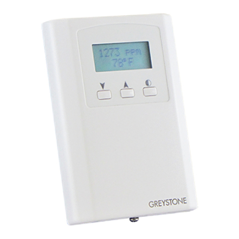
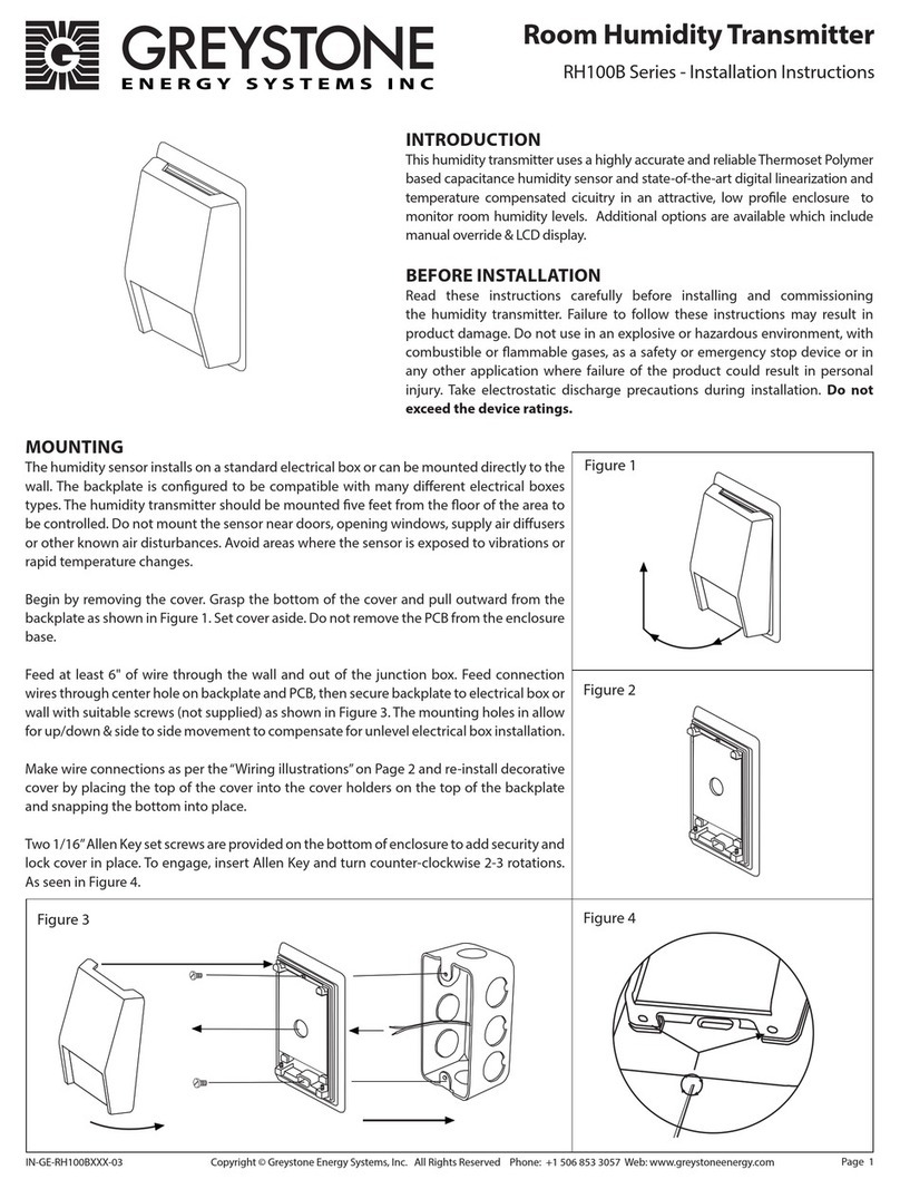
Enclosure Dimensions .............84mm W x 117mm H x 29mm D (3.3" x 4.6" x 1.15")
Enclosure Material.....................White ABS, IP30 (NEMA 1)
Weight ...........................................5.3 oz (150 gm)
Country of Origin.......................Canada
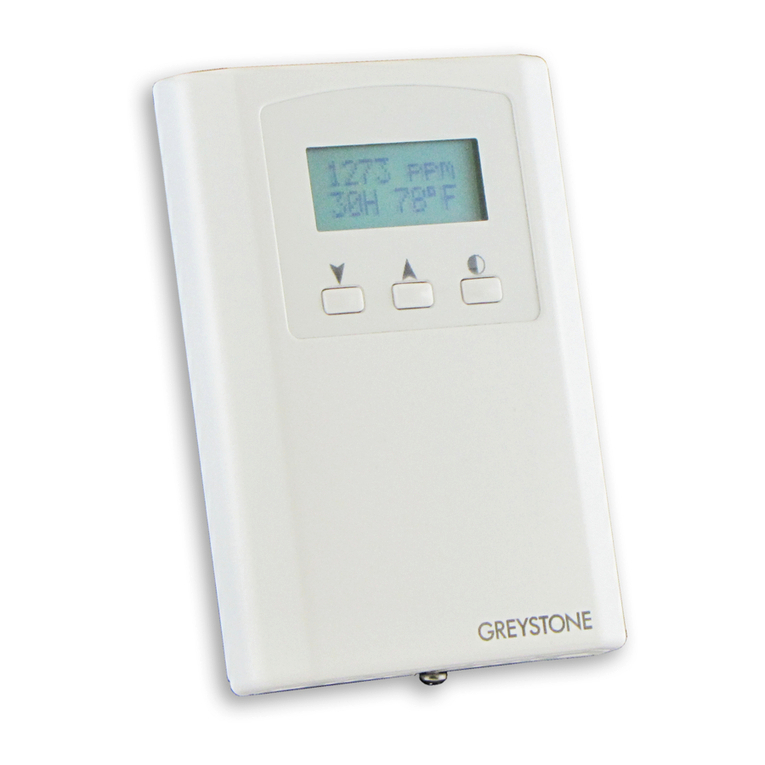
OPTIONAL LCD DISPLAY
Range.............................................00.0 to 99.9 %RH, 3 digit
Size..................................................38.1 mm x 16.5 mm (1.5” x 0.65”)
Digit Height.................................11.43 mm (0.45“)
Symbol ..........................................% RH
OPTIONAL TEMPERATURE SENSOR
Sensor Type .................................Various thermistors or RTD
Sensor Accuracy.........................RTD Class A: ±0.15°C (±0.27°F) @ 0°C (32°F)
RTD 1/3 DIN: ±0.1°C (±0.18°F) @ 0°C (32°F)
RTD 1/10 DIN: ±0.03°C (±0.054°F) @ 0°C (32°F)
NTC Thermistor Type 39: ±0.05°C (±0.09°F), 0 to 70°C (32 to 158°F)
NTC Thermistor Type 55: ±0.03°C (±0.054°F), 0 to 70°C (32 to 158°F)
NTC Thermistor Type 40/46: ±0.1°C (±0.18°F), 0 to 70°C (32 to 158°F)
OPTIONAL SETPOINT ADJUSTMENT
Type................................................Front panel pot, two wire resistive output, 0-10K Ω
Range.............................................0K to 10K Ω standard
Custom spans available...........1K, 2K, 5K, 10K or 20K Ω
OPTIONAL MANUAL OVERRIDE
Type................................................Front panel, momentary pushbutton
Switch ratings .............................50 mA @ 12 Vdc, N.O., SPST
OPTIONAL STATUS LED INPUT (N/A WHEN LCD SELECTED)
Signal Type...................................5 V current limited, 2-wire standard
Color...............................................Yellow (Y), Red (R), or Green (G)
Power Supply..............................5 Vdc standard, 10 or 24 Vdc optional
OPTIONAL COMMUNICATION JACKS
Molex .............................................4-pin header connector to 4-pin terminal block
Requires HHTA - Hand Held Adapter
OPTIONAL FAN SPEED SWITCH
Type................................................Side mounted, 5 position slide switch
Range.............................................O, Auto, Low, Medium, High
Signal .............................................2 wire resistance output : 0, 2, 4, 6, 8K Ω
(Custom ranges available, contact Greystone)
NOTE: The sensor accuracies listed in the specications section apply to the sensing element only prior
to product assembly and may not be reected in the complete assembly.
Due to the measurement uncertainty, it is possible, that the true resistance value of the single delivered
sensor at 0°C can be out of the dened tolerance class. Proling each assembly to take into consideration
lead wire and the attachment method should be completed.
IN-GE-HAHRCXXX-02 Copyright © Greystone Energy Systems, Inc. All Rights Reserved Phone: +1 506 853 3057 Web: www.greystoneenergy.com
