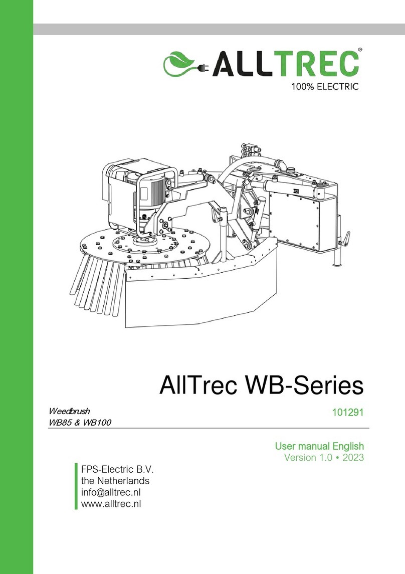
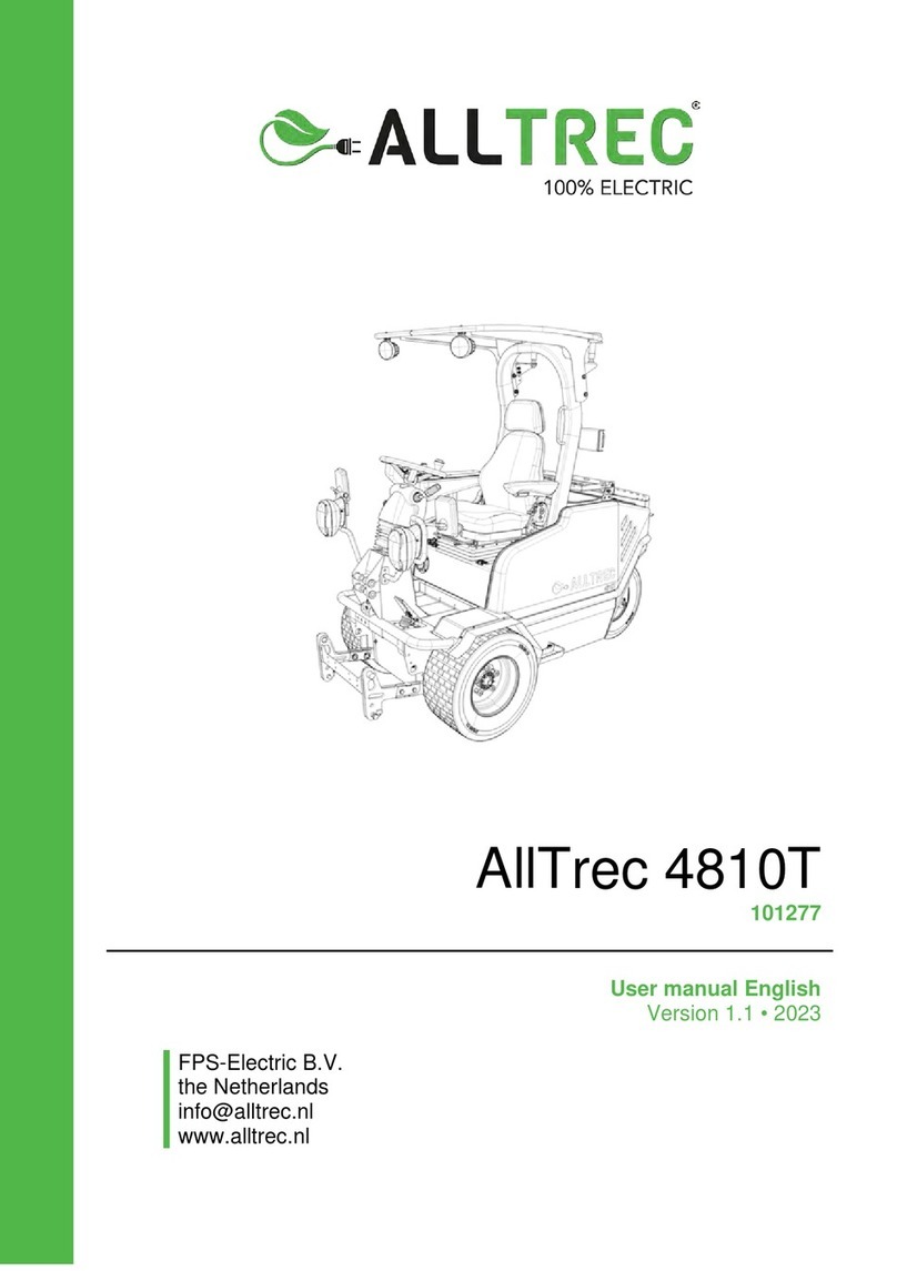
ALLTREC 8015F User manual

AllTrec 8015F
101270
User manual English
Version 1.3 • 2023
FPS-Electric B.V.
the Netherlands
info@alltrec.nl
www.alltrec.nl

INTRODUCTION
AllTrec 8015F 1
FPS-Electric B.V. reserves the right to modify the specifications and/or
components without prior notice. The contents of this manual may also
be modified without notice.
For information about settings, maintenance or repairs not provided in
this manual, please contact your dealer.
FPS-Electric B.V. accepts no liability for damage and/or problems
resulting from the use of parts that are not supplied by FPS-Electric
B.V.
This manual has been prepared with the utmost care.
FPS-Electric B.V. accepts no liability for any errors in this manual
and/or the consequences of misinterpretation of the instructions.
All rights reserved. No part of this publication may be reproduced,
stored in computerised databases or transmitted in any form or by any
means, electronic, mechanical, photocopying or otherwise, without prior
written consent by FPS-Electric B.V.
This also applies to the accompanying drawings and diagrams.
Details
Your Dealer:
Serial number:
Delivery date:

INTRODUCTION
2AllTrec 8015F
Version history
Version
Description
Date (dd-mm-yyyy)
1.0
First version
12-04-2022
1.2
Second version
18-01-2023
1.3
Third version
27-02-2023

INTRODUCTION
AllTrec 8015F 3
Preface
This user manual covers the following: the AllTrec 8015F.
Please read this manual carefully for important information and
instructions before using the AllTrec 8015F.
Save this manual for future reference.
The best results will be obtained when the AllTrec 8015F is:
•Regularly maintained by carrying out preventive maintenance
instructions
•Operated with reasonable care and caution
•Maintained with manufacturer-supplied parts
When this manual refers to “the manufacturer”, this means: AllTrec.
Purpose of this manual
The purpose of this user manual is to ensure that the above product is
maintained and used safely and correctly.
Adherence to the instructions herein will help to avoid personal injury,
equipment damage and/or property damage. It will also increase the
reliability and service life of all components.
This manual must be available within the machine. Operators and
maintenance personnel are required to read this manual before working
with/near the AllTrec 8015F.
This user manual contains information and instructions regarding:
•General description of the product and its components
•Safety of all personnel working with the product
•Operation
•Troubleshooting
•Disposal of the machine
•Disposal of the battery
For any questions or requests for information, please contact AllTrec.

INTRODUCTION
4AllTrec 8015F
Target audience
This manual must be read and understood by:
•Distributors
•Operators
•Maintenance personnel
The manual is primarily meant for the operators and maintenance
personnel.
Requirements for operators
Only adult operators that are at least 16 years old are allowed to work
with the AllTrec 8015F if they:
•Have fully read and fully understood all instructions mentioned
within this manual
•Have checked local legislation and followed the required training
and/or got an appropriate licence before operating an AllTrec
•Fully adhere to all safety measures mentioned in this manual
All applicable local regulations should be observed.
Operators should take the following into account.
1. Maintenance work on the electrical parts may only be performed by:
•A person authorised by AllTrec
•Trained personnel under the direct supervision of a person
authorised by AllTrec
2. Local disassembly and assembly may only be carried out by:
•A person authorised by AllTrec
•Trained personnel under the direct supervision of a person
authorised by AllTrec

INTRODUCTION
AllTrec 8015F 5
Reading guide
Read this manual carefully.
Pay close attention to all special symbols.
When in doubt, consult your supervisor on how to
proceed.
Reading the instructions in this manual helps to avoid dangerous
situations, repair costs and downtime. It also increases the reliability
and service life of the AllTrec 8015F.
This manual uses the following symbols to bring important safety
information to the reader's attention:
DANGER
Indicates an imminently hazardous situation that, if not
avoided, will result in death or serious injury.
WARNING
Indicates a potentially hazardous situation that, if not
avoided, could result in death or serious injury.
CAUTION
Indicates a potentially hazardous situation that, if not
avoided, may result in minor to moderate injury and/or
product or property damage and/or loss of information.

INTRODUCTION
6AllTrec 8015F
NOTE
This shows extra information that may help the user.

INTRODUCTION
AllTrec 8015F 7
EC Declaration of Conformity
The undersigned,
F.P. van de Staak,
certifies that the machine
Complies with the following directives:
The following standards apply:
Rijen, the Netherlands
16-01-2023
F.P. van de Staak
General Director
FPS-Electric B.V.
BRAND AllTrec
TYPE 8015F
- 2006/42/EC Machines
- 2014/30/EC Electromagnetic compatibility (EMC)
- NEN-EN-ISO 12100:2010 General principles of design – Risk
assessment and risk reduction
- NEN-EN-ISO 13849-1:2015 Safety-related parts of control
systems
- NEN-EN-ISO 14982:2009 Agricultural and forestry machinery -
Electromagnetic compatibility - Test
methods and acceptance criteria
- NEN-EN-ISO 21299:2009 Powered ride-on turf care equipment
- Roll-over protective structures
(ROPS) - Test procedures and
acceptance criteria

INTRODUCTION
8AllTrec 8015F
List of abbreviations
ATC Advanced Torque Control
BMS Battery Management System
CP Charging Port
DA Double Acting
EPAS Electric Power Assisted Steering
ePTO Electric Power Take Off
IoT Internet of Things
LFP LiFePO4 (Lithium-Ferro-Phosphate) battery
MSD Manual Service Disconnect
ROPS Roll Over Protection Structure
SOC State of Charge
VCU Vehicle Control Unit
VDC Volts of Direct Current

INTRODUCTION
AllTrec 8015F 9
Content
VERSION HISTORY...............................................................................2
PREFACE ...............................................................................................3
Purpose of this manual ...........................................................................3
Target audience ......................................................................................4
Requirements for operators ....................................................................4
Reading guide.........................................................................................5
EC Declaration of Conformity..................................................................7
List of abbreviations ................................................................................8
CONTENT...............................................................................................9
LIST OF FIGURES................................................................................15
1. INTRODUCTION ......................................................................19
1.1 Intended use .............................................................................19
1.2 Non-intended use......................................................................19
1.3 Use on public roads and motorways.........................................20
1.4 Identification..............................................................................21
1.5 Warranty....................................................................................22
2. DESCRIPTION OF THE MACHINE .........................................23
2.1 Machine model..........................................................................23
2.2 Machine components................................................................24
2.2.1 Front side machine components............................................24
2.2.2 Rear side machine components............................................25
2.2.3 Operating machine components............................................26
2.2.4 Cabin machine components – top front.................................27
2.2.5 Cabin machine components – rear side................................28
2.2.6 Cabin / anti-roll bar ................................................................29
2.2.7 Propulsion, speed control and brakes ...................................29
2.2.8 Traction system......................................................................30
2.2.9 Lights .....................................................................................30
2.2.10 Steering system.....................................................................30
2.2.11 Battery....................................................................................31
2.2.12 Lifting device..........................................................................31
2.2.13 Hydraulic system....................................................................31
2.2.14 Double Acting (DA) function ..................................................32
2.2.15 Frame.....................................................................................32
2.2.16 Fuses.....................................................................................33
2.2.17 12V Battery............................................................................36
2.2.18 Attachments...........................................................................36

INTRODUCTION
10 AllTrec 8015F
2.3 Safety provisions and measures...............................................37
2.3.1 Seat sensor............................................................................37
2.3.2 Adjustable work space...........................................................37
2.3.3 Safety belt..............................................................................37
2.3.4 Main battery connector ..........................................................37
2.3.5 Cabin / Anti-roll bar................................................................37
2.3.6 Electrical boxes......................................................................37
2.3.7 Stickers with warning pictograms ..........................................38
2.4 Technical specifications............................................................44
2.4.1 Dimensions and weight..........................................................44
2.4.2 Drive.......................................................................................46
2.4.3 Tyres, brakes and steering system........................................46
2.4.4 Battery....................................................................................46
2.4.5 Operation and comfort...........................................................47
2.4.6 Lifting device attachments.....................................................48
2.4.7 Double acting (DA) functions.................................................48
2.4.8 Allowed slopes.......................................................................48
2.5 Battery.......................................................................................49
2.5.1 Battery system functioning.....................................................50
2.5.2 Battery usage instructions .....................................................50
2.5.3 Storage after use ...................................................................51
2.5.4 Battery safety instructions......................................................51
2.6 Equipment and options.............................................................52
2.6.1 Machine options.....................................................................52
2.6.2 Energy source........................................................................55
2.6.3 Battery accessories & charging.............................................56
2.6.4 Attachments...........................................................................57
3. TRANSPORT AND STORAGE................................................61
3.1 Transport of the machine..........................................................61
3.2 Storage of the machine.............................................................63
4. PUTTING INTO SERVICE........................................................65
4.1 First inspection..........................................................................65
4.2 80 hours inspection...................................................................65
4.3 Check before every use............................................................65
4.4 Adjusting the steering column...................................................66
4.5 Adjusting and using the seat.....................................................68
4.6 Adjusting the tyre pressure.......................................................70
4.7 Charging....................................................................................71
4.7.1 Charging options....................................................................72
4.7.2 Charging precautions.............................................................73

INTRODUCTION
AllTrec 8015F 11
4.7.3 Charging at a socket – Model A and B..................................75
4.7.4 Charging at a socket – procedure..........................................76
4.7.5 Charging at a charging station – Type 2................................78
4.8 Connecting attachments...........................................................80
4.8.1 Mechanic connection.............................................................81
4.8.2 Electric connection.................................................................82
4.8.3 Hydraulic connection .............................................................83
5. OPERATING THE ALLTREC 8015F .......................................85
5.1 Using the right armrest controls................................................86
5.2 Display ......................................................................................87
5.2.1 Main screen symbols.............................................................88
5.2.2 Attachment status..................................................................89
5.2.3 Warning notifications .............................................................89
5.2.4 Drive mode status..................................................................90
5.2.5 Temperature status................................................................90
5.2.6 Seat notification .....................................................................91
5.2.7 Seat status.............................................................................91
5.2.8 Cover open notification..........................................................92
5.2.9 Battery status.........................................................................93
5.3 Joystick and joystick buttons ....................................................95
5.4 Armrest function buttons and fingertip switches.......................97
5.5 Using the lights .........................................................................99
5.6 Ignition.....................................................................................101
5.7 Driving.....................................................................................102
5.8 Parking....................................................................................105
5.9 Float........................................................................................106
5.10 Cruise control..........................................................................108
5.10.1 Activate cruise control..........................................................110
5.10.2 Deactivate cruise control .....................................................110
5.11 Using air conditioning and heating..........................................111
5.12 Using front window windshield wiper......................................112
5.13 Using cabin light......................................................................113
5.14 Using rear window ..................................................................114
5.15 Use the door’s ajar position ....................................................115
6. OPERATING ATTACHMENTS..............................................117
6.1 Operating mowing decks ........................................................118
6.1.1 Activating the mowing deck .................................................119
6.1.2 Deactivating the mowing deck.............................................119
6.1.3 Joystick functionality for mowing decks...............................120
6.1.4 Armrest button functionality for mowing decks....................121

INTRODUCTION
12 AllTrec 8015F
6.2 Operating weed brush.............................................................123
6.2.1 Activating the weed brush....................................................124
6.2.2 Deactivating the weed brush ...............................................124
6.2.3 Joystick functionality for weed brush...................................125
6.2.4 Armrest button functionality for weed brush ........................127
6.3 Operating leaf blower..............................................................128
6.3.1 Activating the leaf blower.....................................................128
6.3.2 Deactivating the leaf blower.................................................129
6.3.3 Joystick functionality for leaf blower ....................................130
6.3.4 Armrest button functionality for leaf blower .........................131
7. MAINTENANCE .....................................................................133
7.1 Safety rules for maintenance and adjustments.......................134
7.2 Jacking up the machine..........................................................135
7.3 Towing.....................................................................................135
7.4 (Dis)connecting MSD (Manual Service Disconnect)...............136
7.5 Maintenance schedule............................................................137
7.5.1 Safety functions – seat contact sensor................................139
7.5.2 Battery maintenance............................................................140
7.5.3 Cleaning...............................................................................141
7.5.4 Lights maintenance..............................................................143
7.5.5 Electric system maintenance...............................................143
7.5.6 Screenwiper - Quality ..........................................................143
7.5.7 Screenwiper - Reservoir......................................................144
7.5.8 Hydraulic system – Oil level.................................................144
7.5.9 Hydraulic system – Check for leakage ................................145
7.5.10 Hydraulic system – Change oil............................................145
7.5.11 Lubrication points.................................................................146
7.5.12 Gearbox – Check for leakage..............................................148
7.5.13 Gearbox – Oil level ..............................................................149
7.5.14 Gearbox – Change gearbox oil............................................149
7.5.15 Brake fluid – Check level.....................................................150
7.5.16 Brake fluid – Change fluid....................................................150
7.5.17 Brake - Functionality............................................................151
7.5.18 Brake – Backlash check ......................................................151
7.5.19 Frame maintenance.............................................................152
7.5.20 Steering shaft check ............................................................152
7.5.21 Wheels – Wheel bolts..........................................................152
7.5.22 Wheels – Tyres and Tyre pressure......................................153
7.5.23 Wheels – Play on wheels.....................................................153
7.5.24 Wheels – Inline ....................................................................154

INTRODUCTION
AllTrec 8015F 13
7.5.25 Wheels – Rear fusee ...........................................................155
8. MALFUNCTIONS ...................................................................157
8.1.1 Connection lost notification..................................................157
8.2 Risks and/or dangerous situations..........................................158
8.2.1 Defects in the power supply.................................................158
8.2.2 Getting trapped between the lifting device ..........................158
8.2.3 Dirty external components...................................................158
8.2.4 Seat......................................................................................159
8.2.5 Risks during maintenance of the machine...........................159
9. DISCARD................................................................................161
9.1 General ...................................................................................161
9.2 Environmental consequences.................................................161
9.3 Dismantling .............................................................................161
9.4 Waste disposal........................................................................161
9.5 Battery recycling .....................................................................161
10. WARRANTY CONDITIONS ...................................................163
11. ANNEX....................................................................................165
11.1 Checklist when commissioning the machine..........................166
11.2 80 hours inspection.................................................................167
11.3 Maintenance logbook..............................................................168

INTRODUCTION
14 AllTrec 8015F

INTRODUCTION
AllTrec 8015F 15
List of figures
Fig. 1-1 Type plate...........................................................................21
Fig. 1-2 Type plate and serial number location................................22
Fig. 2-1 Machine components front side..........................................24
Fig. 2-2 Machine components rear side ..........................................25
Fig. 2-3 Machine components inside...............................................26
Fig. 2-4 Machine components inside...............................................27
Fig. 2-5 Machine components inside...............................................28
Fig. 2-6 Fuse holder location ...........................................................33
Fig. 2-7 Fuse holder guide...............................................................34
Fig. 2-8 Fuse chart...........................................................................35
Fig. 2-9 Sticker locations - front.......................................................38
Fig. 2-10 Sticker locations – compartments.......................................39
Fig. 2-11 Sticker locations - backside................................................39
Fig. 2-12 Sticker location – steering wheel........................................40
Fig. 2-13 Sticker location – fuse holder..............................................40
Fig. 2-14 Machine dimensions AllTrec 8015F with ROPS.................45
Fig. 2-15 Machine dimensions AllTrec 8015F with cabin ..................45
Fig. 2-16 Battery sticker.....................................................................49
Fig. 3-1 Frontal locations for machine securing during transport ....62
Fig. 3-2 Side locations for machine securing during transport ........62
Fig. 3-3 Rear locations for machine securing during transport........63
Fig. 4-1 Steering column position adjustments................................66
Fig. 4-2 Steering column height adjustments ..................................67
Fig. 4-3 Seat adjustment..................................................................68
Fig. 4-4 Seat heating button.............................................................69
Fig. 4-5 Tyre valve caps...................................................................70
Fig. 4-6 Unbalanced versus Balanced battery.................................74
Fig. 4-7 Charging graph with temperatures .....................................74
Fig. 4-8 Charging control unit - Model A+B......................................75
Fig. 4-9 Charging point ....................................................................76
Fig. 4-10 Display with charging status...............................................78
Fig. 4-11 Attachment connections on the front side ..........................81
Fig. 4-12 Attachment connection on the rear side.............................82
Fig. 5-1 Right armrest with controls.................................................86
Fig. 5-2 Main screen symbols..........................................................88
Fig. 5-3 Main screen explanation.....................................................88
Fig. 5-4 Seat notification ..................................................................91
Fig. 5-5 Cover open notification.......................................................92
Fig. 5-6 Battery levels shown in display...........................................94
Fig. 5-7 Urgent charging notification................................................95

INTRODUCTION
16 AllTrec 8015F
Fig. 5-8 Joystick with buttons and rollers.........................................95
Fig. 5-9 Armrest function buttons and fingertip switches.................97
Fig. 5-10 Light handle ........................................................................99
Fig. 5-11 Light buttons .....................................................................100
Fig. 5-12 Ignition switch ...................................................................101
Fig. 5-13 Joystick with buttons.........................................................102
Fig. 5-14 Driving directions shown in display...................................103
Fig. 5-15 Accelerator and braking pedal..........................................104
Fig. 5-16 Hand brake .......................................................................105
Fig. 5-17 Float functionality in display..............................................106
Fig. 5-18 Float functionality and control buttons..............................106
Fig. 5-19 Joystick with cruise control button....................................108
Fig. 5-20 Armrest cruise control function buttons ............................109
Fig. 5-21 Display cruise control button.............................................109
Fig. 5-22 Air conditioning / heating controls and air vents...............111
Fig. 5-23 Front window wiping controls............................................112
Fig. 5-24 Cabin light.........................................................................113
Fig. 5-25 Rear window.....................................................................114
Fig. 5-26 Ajar position handle..........................................................115
Fig. 5-27 Ajar position handle..........................................................116
Fig. 6-1 Hydraulic connectors........................................................117
Fig. 6-2 Display buttons for mowing deck functionality..................119
Fig. 6-3 Joystick functionality for mowing deck..............................120
Fig. 6-4 Armrest button functionality for mowing deck...................122
Fig. 6-5 Display buttons for weed brush functionality....................124
Fig. 6-6 Joystick functionality for weed brush................................125
Fig. 6-7 Armrest button functionality for weed brush .....................127
Fig. 6-8 Display buttons for leaf blower functionality .....................128
Fig. 6-9 Joystick functionality for leaf blower .................................130
Fig. 6-10 Armrest button functionality for leaf blower ......................131
Fig. 7-1 Jack points on AllTrec 8015F ..........................................135
Fig. 7-2 MSD Safety-connector......................................................136
Fig. 7-3 Frontal traction controller..................................................141
Fig. 7-4 Axle and drive motor (bottom view)..................................142
Fig. 7-5 Axle and drive motor (four-wheel drive)............................142
Fig. 7-6 Screenwiper reservoir.......................................................143
Fig. 7-7 Hydraulic oil tank ..............................................................144
Fig. 7-8 Lubrication points..............................................................147
Fig. 7-9 Lubrication of steering axle...............................................147
Fig. 7-10 Gearbox............................................................................148
Fig. 7-11 Brake fluid tank.................................................................150
Fig. 7-12 Check backlash of brake ..................................................151
Fig. 7-13 Check play on wheels.......................................................153

INTRODUCTION
18 AllTrec 8015F

INTRODUCTION
AllTrec 8015F 19
1. Introduction
1.1 Intended use
The AllTrec 8015F is an universal tool carrier. It is intended to be used
for various work activities in public green spaces in the city and
municipality, at camping sites and at holiday and amusement parks.
Depending on the attachment mounted onto the machine, it is suitable
for:
•mowing
•weed control
•sweeping
•leaf blowing
Use the AllTrec 8015F only for the work activities mentioned above.
The CE marking according to the Machinery Directive does not apply to
other work activities.
If you want to use the AllTrec 8015F for other work activities, please ask
your dealer about the options.
1.2 Non-intended use
The AllTrec 8015F is not intended to be used for:
•transporting goods or people
•seating more than one operator
•towing vehicles
•towing a trailer
•lifting other components other than the attachments that have been
specifically developed for the AllTrec 8015F
•lifting people or animals
Table of contents
Other ALLTREC Farm Equipment manuals