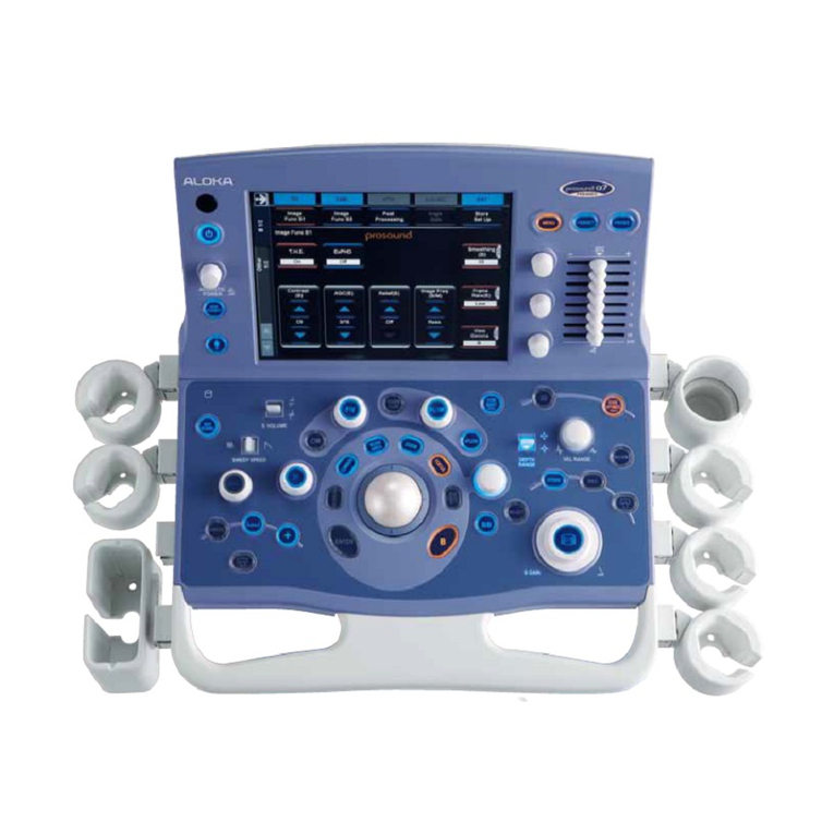
Aloka ProSound SSD-5500 User manual

SPECIFICATIONS
for
ALOKA Ultrasound System
ProSound'" SSD-5500
A Platform for Digital Pure Beam Imaging
ALOI(A
Science 8. Humanity

MN2-0224 Rev. 1
SSD-5500 SERVICE MANUAL Appendix
Appendix-1 Introduction
This appendix is described the revised history of this service manual as Manual Change
Information.
Appendix-2 Manual Change Information
Revisions
Rev. Date Contents Pages ' Note
i
0 18 /May /'98 1st. issue
1 06 /Oct./99 Addition of information for SSD-5500 Ver.3
Change of terms(Moditïcation---_Upgrade, etc.) i
Correction of errata, etc.
I |
1/2 Tifle page Replaced
1/2 Contents Replaced 1/6-4/6
Added 5/6, 6/6
I |
Section 1
1-2ContentsofthisServiceManual ReDlaced 1-1 , ,
Section 2
PRECAI.rrlO NS Replaced 2-1-2-4
Deleted 2-5, 2-6
I I II
Section3
3-1 Repair work on the description of Replaced 3-1-3-5
Service Manual
3-2 Upgrade work on the description Replaced 3-6-3-11
i
of Service Manual i
Section4"i
PrincipleofSystemOperation Replaeed 4-1-4-146
Deleted 4-147-4-166
I I •
Section 5
SCHEMATICS Replaced 5-11
Added 5-87-5-168 I•
2/2 Title page Replaced
2/2 Contents Replaced 1/4-4/4
Apndx-1

MN2-0224Rev.1
SECTION 1 How to use this service manual
1-1 Service Manual
1) This service manual has been prepared for persons in charge of repair at the field.
2) This service manual is compiled according fo the following basic principle. "For service, pick
out a faulty PCB and replace it with a new PCB ."
3) Make the best use of this service manual, making also reference to available technical support
information such as "Technical Bulletin".
1-2 Contents of this Service Manual
1) The equipment is repaired by PCB replacement. Therefore this service manual does not
include the circuitdiagrams of the PCB unit. For the function of each PCBs whose circuit
diagram is not included, refer to =SECTION 4 PRINC[PLE OF SYSTEM OPERATION".
In "SECTION 4", Specification of Systern, Principle of System,System Block Diagram, PCB
Block Diagram, the explanation of each PCB Block Diagram, and signal list are described.
However, "Cable Connection Diagram", "CircuitDiagram of PCB equipped with the panel
switches which are easily exchangeable at the field" and "Circuit Diagram composed of
general circuit such as TV monitor and Power Supply unit" are described in "SECTION 5
SCHEMATICS".
2) For changes and modifications of as well as additions to specifications, if any,prompt
information will be given toyou by means of "APPENDIX Manual Change Information".
OIMPORTANTO Always observe the manner specified for replacement,addition, or
deletion of "Manual Change" fo prevent missing of necessary
information and keeping of erroneous information.
1-1

MN2-0224 Rev. 1
SECTION 2 PRECAUTIONS
2-1 Precautions Against Electrical Hazards to Serviccman
When disassembling lhe equipmcnt after checking il for a trouble symptom, givc tare to the
ïollowing:
1) Be sure fo unplug the equipmcnt before disassembly.
2) Bc sure fo turn off the main switch on thc cquipmcnt whcn rcmcwing clcctrical paris such as
PCBs, probe, and table.
3) Safety alerl symbols
The indicaticm //_used on this equipment and in this service manual have the
following
meaning.
"Indicates apotentially hazardous situation which, if not avoided, may result in minor or
moderate injury.'"
"A caution message is inserted here. "
2-2 Prccautions Against Mcchanical Hazards to Scrviccman
When disassembling the equipment, give care fo the following fo prolect serviceman from
hazards :
1) Keep the working environment neat.
Wear working glcwes fo protect your hands from gelting injured by burrs on the unit and
casing.
2) Use only proper tools suited lo work being ruade.
3) Be sure to observe the specified disassembly procedure shown in SECTION 9.
4) Take sufficient care not to damage component with undue load.
2-3 Precautions Against Germ Hazards to Serviceman
1) When il is necessary fo touch the equipment, options and/or other peripheral devices ai a
customer who uses intraeorporeal (transesophageal, transurethral, transvaginal, transrectal)
probes that need sterilization, take special care to protect your hands against germs,
irrespective of the usage of the equipment: whether il is used in the operation room or nol.
2) Service tools are subjecl lo germ pollution in hospitals and, therefore, need periodical
sterilization.
3) Be careful nol to directly touch anything assurnable fo bave germ pollution. If necessary, ask
lhe customer for effective protection against germs.
2-1

MN2-0224 Rev. 1
SECTION 3 BEFORE REPAIRING
3-1 Repair work on the description of Service Manual
The typical processes for the repair work are shown as the Flow Chart on the ncxt page. Do the
repair work according to this procedure. In the case of upgrade of thc Technical Bulletin or
Upgrade Kit, see lhe next item 3-2.
Each procedurcs of flow chart are numbcred to refer its detail shown from page 3-3. Furthermore,
-.
the Flow Chart and ils explanation show the lime when each section of service manual are required
on repair work. This is a guide for lhe usage of service manual.
The service manual is very important for the repair work, especially readjustment and
performance check al'ter completion of repair work. This is fo keep the safety and quality of
equipment. If you make them, you have fo describe thal the treatment has been done according fo
lhe applied section of service manual, on the repair report or the like.
The circled numbers shown in the Flow Charl on nexl page, are corresponded lo lhe procedure
number shown from page 3-3.

MN2-0224Rev. 1
SECTION 4 Principle ofSyslem Opcration
4-1 System Specifîcations
Scanning System Electronie Linear Scanning
Electronic Convex Scanning
Electronic Sector Scanning
Simultaneously Attached Probes
EleeIronic Probe 3 probes + 1 dummy conneclor
Independent.Probe 1 pr_)be (the Option unit,is required)
Operating Modes: B, M
D (PW Doppler,CW Doppler, STCW Doppler)
Flow (Velocity/Variance,Power Flow)
M, D Mode Display Scroll display, Moving Bar display (Ver. 1.1"-)
Sweep Speed 7 speeds selectable (1,1.5,2,3,
4,6,8 Sec/Plane)
Diagnostic Distance: 2-24 cm (Each 1)robe has a diagnostic distance limit.)
Display modes
Electronic Linear Electronic lndependent
Electronic Convex Seclor
B, B-Zoom,2B O O X
B (F), B (PF),O O ×
B(F)-Zoom,
B(PF)-Zoom
2B(F), 2B(PF)
B/M0 0 x
B(F)/M(F) O O ×
B(PF)/M(PF)
B/PW Doppler O0 X
B(F)/PW Doppler
B(PF)/PW Doppler
B/CW Doppler X O X
B(F)/CW Doppler
B(PF)/CW Doppler
M0 O X
M(F),M(PF) O O X
PWDoppler 0 0 ×
CWDoppler × O O
O : Possible, × : Impossible, F: Flow, PF: Power Flow
• The option unil is required for connection of Independent probe.
4-1

I*IL i'1"i °l'l°l.l,l,luivl.l.l,l:,12131,1s,12131,15,12131,15,1_1_1,15,12131,1s,121»1,1_,1=131,15,121=1,1=,121=1,15,Izl31,1s,Izl=l,l:,121=lois,l=l=l,ls ,lz!=l,15,l»l_l,ls
PSU $5000"
P600 POWER SW
H__.n@:3111 -O4R I (mele_SW I
•I«mmi:l_llA]lmole=_ ............................................... /kH-_ AVV_ _'16" " SW L-S 6]_'W13(vt 14)(EWlG)
/"-.:"".A : I AC OUT(L)
UL1015TEWAWG?O BRI",J lotmW,_I.$TO-81T.2SON(JST}
AC OUT(L] \ i _ UL1015TFW AW_70 RItJ
,«o0,{._ v _.ii;_,,_ou...)
ACAC'N(L),N(N}3 /_ ! ! ULlO15TEW /WV_3'2'ORRN ' ' '__ -}!i 52 A«AC'N(L'
4 _v r :" !UL101STEW AWG20 RItJ _ "
IN(N)
_ 3
AH-6AVVG2"
_H
(31 LABEL PS00N i_l:P_{_
_,
_ ../ ,s,z,,,,_u,.-,,-__....
•__ InsulokToetT18R_// Po-er SZ, P-|t=_:'t____K
_ . . _ _-__,_,...:_.°.._.
I
'k_2__/ç)
l-][-]C_0mm ;7o,,__ i< 7o,w. )u_
DDc,«OE,MI_.,_-&__/I:.BE _1:10c2_,1020=,)["I'}
C3
o
2:
U,_Z
nï
N°
1",3
_:P6001_,_ ____OP-32-SSD55n*-3 _(_,ql"f"x_.
;;O
oe--,
___1 I.'ï'.'-_J[.__.'' _l," ; 'l MC336648
UNITS L-u_J-_u-__-,,,.=

SERVICE MANUAL
PRO SOUND
SSD- 5500
2/2
English Edition
DocumentNumber "MN2-0224
Document Revision " 1
Copyright_ ALOKA CO.,LTD.
FILE 2

MN2-0224
SECTION 6 TROUBLESHOOTING
6-1 Introduction
This trouble shooting makes integral part of the Service Manual. And it has been prepared for the
persistent purpose of providing for repairing guidelines.
What has been described herein, moreover, is subject to the prerequisite for a repair to be made by
replacing a PCB.
6-2 Precautions
To prevent a new problem (seeondary disaster) from taking place in the proeess of trouble
shooting as described herein,every engineer concerned should duly take the following precautions:
1) Never remove any part from the electric system, including PCB, probe, cable, etc., before
powering off the equipment.
2) Do not proceed to a disassembly of equipment without observing the established disassembly
procedure. Be careful enough for wrongly disassembling the equipment would damage or
break it down.
3) To make certain of a voltage and/or a signal waveform, it is necessary to thoroughly know the
specification and handlmg procedure relating to a measuring instrument employed.
4) To ground a measuring instrument probe or the like, it is naturally necessary to know where a
signal to determine is grounded. Before using the instrument, moreover, make certain for
whieh the grounding terminal is intended,analog, digital, alternating current, direct current,
high voltage or low voltage.
I....................... I
| OCAUTIONO Failure to ground properly might result in an incapability ofobserving an |
| accuratevoltageor waveformor in a probabilityofburningoutthe |
I .... _measuring_-- --instrument---- or_ultrasound_-- --diagn°stic--_ equipment._-- --°r both._-- -- -- I
5) Do not fit a measuring instrument probe or the like to a measuring point before turning off the
ultrasound diagnostic equipment.
I I
OCAUTIONQ To determine an especially high voltage,it might rupture a circuit in
I I
the ultrasound diagnostic equipment. Besides, it might endanger a
I I
I_ _ engineer or engineers eoneemed. I
6-1

MN2-0224
SECTION 7 ADJUSTMENT PROCEDURE
7-1 Introduction
The adjustment points shown in this adjustment procedure are points where the actual ultrasound
image is,directly adjusted.
7-2 Attention
In order to avoid some new trouble created by this adjustment procedure manual, the person
performing this adjustment should be restricted to someone who has undergone the Aloka approved
training course and who has a high level of technical expertise and knowledge.
Also, by ail means investigate beforehand whether the trouble you are attemptmg to solve by
adjustment is caused by faulty adjustment or by the failure of one of the circuits. Smce
indiscriminate readjustments can be a hindranee to restoring the equipment's original performance,
please exercise great caution in performing adjustments.
When aetually engaging in adjustments,be eareful espeeially in the following points.
1) Begin the operation only after switehing on the power and letting it warm up suffleiently.(30
minutes or more have passed after throwing the power switch ON.)
2) When adjusting variable resistors,do not exert greater force on the PCB than neeessary.
3) Some ofthe variable resistors used in S.M.T. (Surface Mount Technology) may be smaller in size
than those used in the past. When adjusting these devices, be sure to use a driver thatis
appropriate for each specific variable resistor.
4) Do not touch any variable resistor or any variable eoil, etc. whieh is not specifieally indieated in
these procedures. There is danger of altering the circuit to the pointwhere restoration of funetion
will become impossible.
7-3 Tools and Measuring Instruments
The tools and measuring instruments which are ordinarily necessary when perfonning
adjustments are as shown below.
1) Probe Convex : UST-9114-3.5
2) Driver : for +M3
: Adjustment driver
7-1

MN2-0224
SECTION 8 PERFORMANCE CHECK
8-1 Introduction
"Performance Check" describes the items to be confirmed for the maintenance of an equipment
quality and safety under the circumstances referred to below.
•Once a repair work has been donc,
• Once an improvement, for a problem or the like,has been made,
• Once a change as to upgrade the functions and/or specifications has been made,
• When a periodic inspection is made.
8-2 Precautions
Unless otherwise specified, this performance check must be conducted with ail coverings attached
in place and under the following environments:
• 30 minutes or more have passed after throwing the power switch ON.
If the performance check specified herein should be condueted after a repair,an improvement or
an upgrade, make certain of the following:
•Ail the PCBs removed are reconnected properly.
• Ai1 the connectors removed are reconnected properly.
• The replaced ROM and others are mounted in place on a printed circuit board.
The power pin, in particular, should never be mistaken for the GND pin.
• The unnecessary ROM is not left behind inside the equipment.
• Tool, measuring probe,and the like are not left behind inside the equipment.
• Optional components and grounding cable are properly reconnected.
• Screws and the like are not left behind inside the equipment.
8-3 Making Entries in Repair Report
Upon completion of the check, enter findings thereof in such a form as repair report or the like.
And present it to the user. Keep a copy thereof in custody.
8-1

MN2-0224Rev.I
SECTION 9 DISASSEMBLrNG PROCEDURE
] SSD-5500 Disassembling Instruction I
..............;. i........1
.....!_..i..i;ii.i...................ï!i......___.ii]
I
S_i_t____a!______._____.._.__6_:__a__ë__................:........................1
t ____i__iii_fli____i!i___aiii__ailii_e_ili___!io_ï__,',i___-S_s_!___!'i_:.!i!!!iii__iii_'/'t
I. 19:1Rem6ë_e iii_fi; _e_e[_i__i_{6ç(ii,___a,_!i__il ,_;,_;ilillii;ii;i!!ilil;;i!;i;__'_i;iiilliiliiiiii!iii;i;iiii'_ili;iiiiiii__il !i ii;iiiill'_ii'_,:ii; iiii'_:_iiii! iii; ;i i':i;;ii!'_ii_,ii!i!iill;!i'. i!i!il;;ii;,.il;:,:.;!!i;ii!;i;i !;::i;; '.i;;i; !'.t
i iill iii:,ii ! '.:. i !_ ]
I__3.Rem__i__i!i!_ï:_iiRS_'_!i_iil _i_ illil_:il'_i:_i'_ii!ili'_ii'_ii__'_iiiiii_:i!__!iiii'_iiliiilil__i__ii!iili__il!iiiiiiii'_iii'_iiiii__iii':i'_i__ii!'_iiiiiiili;ili!iiiiii__iililiiiiiiii':iili_iii'_iilli'_ii!:_fil!iii'_iiiiilii!i!iiiiiii!',iiil!'i__iiiii:,i!i_i::iiiiiiiili',ili:,_::_ ii:i_:i!il;i!1
I:.1iSii__aa__iiis___ii:___,_i',__aliii_:_e__Siii',___aii',iiiii!i'_ili'_i',iiiiiii'_iiiiiiiii':iiliiii',iiiiiiiii',i',iii',i',filili;iliiiiiiiiii',ii_iiiiii',iil',iil!ili!i!i',iiiii',i_,iiiliii',i',iiiiiiiii'_iiiii:___:,i_ili::i_ii:,:::iili_:_ii!i::_i__!::;ii_ii_,i__,ii1
I:_i_i6!_iRë_e____',ii_ïlii__u_iiO_ïï_ii_:_';_i_iii_i':i_i:,i__!___i_!_i___i_!i___!_i___ii_!_____i_i!_____i____i_iii___.___!________________!__!!::i!':ii:,l
:vc_!s_-__! i ............................................................. il . l
Iii1;;9:;;i Re_oçi6_i;i_fi i#Aë_;ii ii!iii;i;iiiiliii!i.ii!ii!ii.iiii!ii:iii ;i ii;i !:!;;iii!iii:i:!i:il;ii;;ii:ii;iliii!!:!iiiii!;:i i::i!;:ili iii;i:::i::i.iiiii;iiiiii:.ii;:iiliiiiiiii::iii::!i!::;!!::ii;i:iil:.iiii!!!iiii!:iiil]
]:i2o; iRë_o_ia_iiii__iii_til _t_i ililiiiiii !ii::iiiiiiiiii:.iii!iiill:ii::!:ii:iiiiiiiil!iii :.iilii.iliiiii:.iiii.:il::i; i::ii:ii:-iiiii!ii!iiii!iiiili.i:iiiiiiiiiiilli:i!:ii!i:ilii!i:.ii::iiii!!ii:::iil:::i:i:ii:/i:ilt
9-1

Recept_.on: 11/12/g8 3:13; 0422 45 4058 ->I.S.M. MTL.-; Page1
11_12_(_)17"01__ CMEG/ISM =_ALOKA BXPORT TOKYO PO!/04
ALOKA_ CO., LTD. __ c,,_,,_,=-,»-,o_o
6-22-1,Mure. Mitaka-$hi, Tokyo181, 3:apanTEL (Japan) 422-4B.5595
TO Date: 12 November 1998
COMPANY "ISM " FROM: T. Tsuta, SalesSe_
ATTENTION" Be.mard Charbonneau International, Marketing & Sales Department
RE: Your fax TSUTA 117 of.98.10.23on DC in cable
We aresorry for our long :sîlënce.
L-CABLIE_586 is cable between PCB in Physiological signal Unit insideof theunit and6-
pin-D!N connector for De-IN for ECG of SSD-2200/PEU-5500. L-CABLIE-57S is ECG oeble
for 88D-2200/PEU-5500. ---
If you would like to put ECG signal into 6-pin-DC-IN of our system, we have to design
special cable.We have to bavefollowing your extemal EGG specs unit to design special
cable for DC-IN from extemal ECG unit.
..
I 1. Mode/number
i 2. Electric circuit diagram
3. • Output spëcification sheet including following specs.
a. Outputivoltage range and current range
b.output impedanee
c. Electric partls speo sheets of output circuitry
d.:Mechï_nicai dimensionl o[output connector
e, Wi6ngidiagram of output conne¢tor
4. One sample of connector to beconnected with output connector of your ECG
We arelooking forward to hearing you on the above.
_'eSt regards.
,, --..__
L _
ï
«•
;.... -'_:k-__" :_"V ......
.. _ ._"_,...,.
,
•
• t_q_,,,,_, ,_,,,,__ ,.,.#
..

MN2-0224
SECTION 11 SERVICE INFORMATION
11-1 Introduction
This section provides information which the service engmeer must know and information useful if
he knows, when repairing.
11-2 Maintenance Menu
The maintenance menu offers a function to help the service personnel only repair or inspect the
cquipment and upgrade the software. This function is not open to the user.
I I
IOCAUTIONO To make the maintenance function invalid, it is necessary to once turn offthe I
I I
tpower. After performing operation using the maintenance function, be sure to I
!turn on the power again. I
11-2-1 Starting the maintenance menu
1) Press the Preset switch to display the Preset Menu.
2) Press CTRL+ S. (The maintenance menu will be active.)
3) Display "Other" from the menu and select "MAINT."
MENU Other
Maintenance MENU
11 -1

MN2-0224Rev. 1
SECTION 11 SERVICE INFORMATION
11-2-2 Functions of the maintenance menu
1) Version
"Version" is the funetion whieh displays the versions of the equipment hardware and
software and the connecting situation of options on the TV monitor. Select display or non-
display by using the Version selection in the maintenance menu.
ALOKA SSD-5500ALOKA 83D-5500 S/NM*****
HARDWARESOFTWARE HARDWARE SOFTWARE
DBF : BF**-*.*.* OS : OS**-*.*.* DBF : BF**-*.*.* OS : OS**-*.*.*
CI=1 : *.* SYSTEM : CS**-*.*.* CI=] : *.* SYSTEM : CS**-*.*.*
SDP ' *.* DATABASE•PM**-*.*.* SDP : *.* DATABASE :PM**-,.,.,_""-,,
VFA : *.* VFA : *.* '
I I I
MMBW• lU**-*.*.* MMBW• IU**-*.*.* . SYSTEMVersion Displav I J
I
I..... I
OPTION OPTION
UCW-5500 :ACTIVE PEU-5500 : CONNECT]NG 96ch SCR INDEPE"rDl VOL
CNM-6 : CONNECTINGDMS-5500 :CONNECTING STCW DMSFAM Flow PROF
TISSUE : ACTIVEEU-7054:CONNECT]NG Physio Non INT THE K!
B]POLACHE A-SMA
Ver.1and2 Ver.3andhigher
J
A-S1VLA, is always displayed in
this area,but it does hot perform
until the KI (option) is installed.
1)-1 Display of HARDWARE/SOFTWARE
These each item are shown version of hardware and firmware with PCB, and
version of"FILE-SET".
The FILE-SET have following descriptions.
DBF : Flash memory loading data for Digital Beam former
MMBW : Prograrnming for DIU
OS :MS-DOS, autoexee.bat, eonfig.sys etc.
SYSTEM : System programrning,ARTOP programming,
General purpose CPU programming, etc.
DATABASE : Parameter for eaeh probe
What is FILE-SET
The "FILE-SET" is set of files to refer the memorized data-file and firmware into hard
disk drive for software or hardware, and the files are arranged in each functions.
SlMPORTANTS The version information of file-set is stieked on hard disk by label.
When upgrading, the version label must be updated by label
replacement according to installation procedure.
11 -2

MN2-0224 Rev. 1
SECTION 11 SER'vICE INFORMATION
1)-2 Display ofinstalled or connected OPTION
<Ver. 2 and lower>
CONNECTING : Show optional that hardware is added
ACTIVE : Show optional that software is added
Non-ACTIVE : Show optional that hardware is added without necessary software
<Ver.3 and higher>
Show optional that function is added
iOCAUTIONS The condition of connected or installed options ean not check without this i
I I
ifunction, to detected these information when starting the equipment. I
I !
I Therefore,you can't checkthemwhen the equipmentnot started. I
iThe some function (option) will be active or not by only software I
I I
I installation with floppy disk, these function lostby hard disk replacement I
I orresettingofbackupdata. !
b
SlMPORTANTS When you make eonntaet to teehnical support for ser_,ice, be sure to state ail
the information displayed under "Version" together with the serial number.
2) Gray Scale
This function allows the gray scale to be displayed on the TV monitor. Select display or non-
display by using the Gray Seale seleetion in the maintenance menu.
11 -3

MN2-0224
SECTION II SERVICE INFORMATION
3) Color Scale
This function allows the color scale to be displayed ail over the TV monitor. Select display
or non-display by using the "Color Seale" selection in the maintenance menu.
! ......................................................... "-I
!
I Reference The color scale generator is installed on the "ENCODER" PC board, i
J
4) Probe Code
This function displays the probe code eonneeted. Select display or non-display by using the
Probe Code selection in the maintenance menu.
ALOKA
/__ _ A Date
/_ \ "Time
/\ Probe FREQ.
ustioPower
b....................
__ Thisis thedisplavwhenUST-9114-3.5is
- "------- ,./connectedto Probë Connector 3.
PROBE1 :FF PROBE2:FF PROBE3:36B _ I
PROBE4:FF PROBE5:FF _ I
11 -4

5) Panel Test
This function is used to automatically light in order all of the LED lamps mounted on the
panel switches. Two kinds of LED lamps (orange and green) are mounted on the switches on
other than the full keyboard. They automatically light in order by color.
The panel test is performed by selecting "Panel Test" from the maintenance menu. During
the execution of the panel test, the words "Panel Test" are displayed in the message display
area.
6) Serial No.
This funetion is used to register or check the serial number of the equipment and to
authenticate the upgrade.
Input the serial number
[xxxxxxxxxx]
Press SET sw to proceed
Quit: Press Mark Ref sw
7) Info
This function displays part of the settings in the system in real time. Select display or non-
display by using the Probe Code selection in the maintenance menu.
ALOKA
/___O Date
Tirne
ProbeFREQ.
____.ï u__:!___ç___ï___:__
B/W B FIX
PRF = ***KHz
N= ** System Turbo= ***
FLOW DOPPLER
V Range = ***KHz V Range = ***KHz
PRF = ***KHzPRF = ***KHz
N=** N=**
Turbo = ** Turbo =**
PRFfrRB = ***KHz PRF/TRB = ***KHz
Sample Depth= ***cm
Flow Depth = ***cm
Flow Limit = ***cm
11 -5

8) Track III
Display acoustic power
*4' FDATraok3TEST** MI[0.0000]DVA [**.*__] i ALOKA
TIS[0.0000] DVA [_*.*V]
Ispta[ ]TIB[0.0000]F.R [**.*]
Isppa[ ] TIC[O.0000]T.V.RNG [*****]
i_i_;iNi;iiiiNiliiiiii__i
,,ii.:...-iiiiiii_N.-"ii__ii:____jii--_i_::,
__i_N_ Information formore detail
9) Preset Copy
This function is used to copy all the preset data including the COMMON preset and
measuring function to the floppy disk.
(ï) Insert the floppy disk (3.5-ineh, 2HD, 1.44MB, DOS format) in the floppy disk drive of the
equipment.
_) When you select ,Preset Copy", the message "Ready?" is displayed in the message area on
the TV monitor. Select the SET switch on the control panel. (Interrupted with Mark Ref)
(_) The message "Are you sure?" is displayed in the message area on the TV monitor. When you
select the SET switch on the control panel, ail the preset data is copied to the floppy disk. The
message "Copying ...." is displayed blinking in the message area during eopying. None of the
panel operations ean be performed during eopying.
@ After the eopying ends, the display returns to showing the message "Ready?." Select "Mark
Re£'on the control panel to terminate the function.
11 -6

MN2-0224
SECTION 11 SERVICE INFORMATION
Message displayed during reading
Now Loading ....
@ Display when a disk of the wrong disk number is inserte.d
"SET": Retry
FalseDisk! "CANCEL": Inte.rruption of operation
Insert correct Disk and press "SET".
Quit : Press "CANCEL".
I SET CANCEL I
@ Display when a disk already used for upgrading is inseroed
CautionT "SET": Retry
This Disk has been already used
and invalid. "CANCEL": Interruption of operation
Insert New Version up Disk
and press "SET".
Quit : Press "CANCEL"
@ Display when a wrioe-protected disk is inserted
Caution !
This floppy disk is write-protected.
Please setup write enable mode.
@ Display when loading data into the flash memory is started
When step @ ends,the screen shown at
Loading data into the Flash memory.
Please press "SET" left automatically appears.
(Systemstarts AutoReset) "SET": Retry
Quit: press "CANCEL"
"CANCEL": Inte.rruption of operation
Table of contents
Other Aloka Medical Equipment manuals