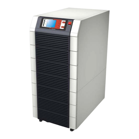
Alpha Outback Energy Sentra XL User manual

Table of Contents
1. Important Safety Instructions .............................................................................................. 3
1.1 Important Notice .............................................................................................................................. 3
1.2 Storage Instruction .......................................................................................................................... 4
2. Introduction ........................................................................................................................... 4
3. Set up .................................................................................................................................. 4
3.1 Inspection ........................................................................................................................................ 5
3.2 Unpacking ........................................................................................................................................ 5
3.3 Selecting an Installation Position ..................................................................................................... 6
3.4 UPS Position ................................................................................................................................... 7
3.5 UPS Front Panel............................................................................................................................ 10
3.6 UPS Rear Panel ............................................................................................................................12
4. Installation ........................................................................................................................... 17
4.1 Connect Utility and Load ................................................................................................................17
4.2 Connect Network Surge protection ................................................................................................18
4.3 Connect Computer Interface Port ..................................................................................................18
4.4 Connect Extended Battery Bank ...................................................................................................19
4.5 Connect Extended Battery Bank to UPS .......................................................................................20
4.6 REPO Switch .................................................................................................................................21
5. Operation ............................................................................................................................ 22
5.1 Switching On the UPS ...................................................................................................................22
5.2 Switching Off the UPS ...................................................................................................................22
5.3 Plug-in Charge...............................................................................................................................22
5.4 Auto-Restart ...................................................................................................................................22
5.5 Alarm Silence .................................................................................................................................22
5.6 Self Test.........................................................................................................................................23
6. UPS
Maintenance
................................................................................................................. 24
6.1 Battery Replacement .....................................................................................................................24
6.2 Replacing Batteries ........................................................................................................................26
6.3 Recycling Used
Batteries
...............................................................................................................28
Page 1 to 32

3
7. Communication ................................................................................................................... 28
7.1 DB-9 Connector .............................................................................................................................28
7.2 Options for Intellislot SNMP Card (Optional) .................................................................................29
8. Specifications ..................................................................................................................... 30
9. Signalling Circuit Connections .......................................................................................... 31
10. Warranty and Service Information..................................................................................... 32
Page 2 to 32

1.
Important Safety Instructions
1.1
Important Notice
SAVE THIS MANUAL – This manual contains important Instructions that must be followed during the instal- lation
and maintenance of the UPS.
The UPS has its own internal energy source (battery). A voltage may be present at the output termi- nals
even when no AC input power is available.
Make sure that the AC utility outlet is correctly grounded.
Do not open the UPS, as there are no serviceable parts inside and your warranty will be void.
Do not repair the unit yourself. Contact your local supplier or your warranty will be void.
Make sure that the input voltage of the UPS matches the supply voltage.
To prevent the UPS from overheating, keep all ventilation openings unobstructed. Do not place any- thing
on top of the UPS. Keep the UPS rear panel at least 20 cm away from the wall or other objects.
Make sure the UPS is installed in an appropriate environment where the ambient temperature is 0 to 40°C
(32 to 104°F), and humidity is 30 to 90% non-condensing.
Do not install the UPS in direct sunlight. Your warranty will be void if the batteries fail.
Install the UPS in a temperature controlled indoor area that is free of conductive contaminants (not
designed for outdoor use).
Dusty, corrosive, or salty environments can damage the UPS.
Install the UPS away from objects that give off excessive heat and areas that are excessively wet.
Do not install the UPS in an environment with sparks, smoke or gas. Not for use in a computer room as
defined in the Standard for the Protection of Electronic Computer/Data processing Equipment,
ANSI/NFPA
75.
If liquids enter into the UPS or foreign objects are dropped into the unit, the warranty will be void.
The battery will gradually discharge if the system is unused for extended periods.
If unused, recharge the UPS every 2 to 3 months. If this is not done, the warranty will void. The batter- ies
will automatically be recharged and kept in good condition if the UPS is installed and used.
This UPS supports electronic equipment in offices, telecommunications, process control, medical and
security applications. Only authorized personnel must install the UPS in the following locations:
a.
Medical applications directly related to human life.
b.
Elevators, metro (subway) system or any other equipment related to human safety.
c.
Public security system or critical computer systems.
Do not install the UPS in an environment with sparks, smoke or gas. Not for use in a computer room as
defined in the Standard for the Protection of Electronic Computer/Data processing Equipment, ANSI/ NFPA
75
Make sure the UPS is completely switched off when moving the UPS from one place to another. It may
cause electrical shocks if the output is not completely switched off.
Page 3 to 32

5
A battery can present a risk of electrical shock and high short circuit current. The following precau- tions
should be observed when working on batteries:
a.
Remove watches, rings, or other metal objects.
b.
Use tools with insulated handles.
c.
Wear rubber gloves and boots.
d.
Do not lay tools or metal parts on top of batteries.
e.
Disconnect charging source prior to connecting or disconnecting battery terminals.
f.
Determine if battery is inadvertently grounded. If inadvertently grounded, remove source from
ground. Contact with any part of a grounded battery can result in electrical shock. The likelihood of
such shock can be reduced if such grounds are removed during installation and maintenance
(applicable to equipment and remote battery supplies not having a grounded supply circuit).
Do not dispose of batteries in a fire. The batteries may explode.
Do not open or mutilate batteries. Released electrolyte is harmful to the skin and eyes. It may be
toxic.
1.2
Storage Instruction
Store the UPS in a location where the temperature ranges between -15ºC to 40ºC (+5ºF to 104ºF).
For extended storage in moderate climates, the batteries should be charged for 12 hours every 3 months. Connect
the UPS to the utility supply and switch on the input breaker located at UPS rear panel. Repeat this procedure
every 2 months if the ambient storage temperature is above 30°C (86ºF).
2.
Introduction
The UPS features a tower/rack convertible design, a single AVR boost and single buck, pure sine wave output, a
user friendly LCD display, a built-in customer option slot, hot swappable batteries, and a USB/ RS232
communication interface. It can be connected to external batteries to extend run time as much as needed and
provides a flexible back-up system for critical file servers, minicomputers, network switches and hubs, and many
other applications in tower or rack mount formats.
The sine wave output is compatible with the requirements of many types of loads.
A user friendly LCD panel displays the system status including the load level, battery level, AVR-
boost/buck, and fault status.
90% efficiency in the normal mode meets high energy saving standard and reduces noise and heat.
Easy swappable batteries lets the end user swap the batteries instead of sending the unit back to the
factory.
A cold start function enables the UPS to be switched on without being connected to the utility power.
Optional communication software allows the UPS to be controlled and gracefully shut down when the
utility power fails. It also allows the user to remotely test the major operating functions of the UPS,
communicate via an SNMP/web/network optional card, access the UPS functions via the web, and alert the
users via SMS messages.
The user-friendly plug and play design allows the unit to be easily installed by the end user. All units up to 3
kVA are supplied with input cables and output sockets.
The plug-and-play USB/RS232 interface conveniently offers a plug-and-play USB or an RS232 port for
connecting with other IT products.
Page 4 to 32
3.
Set up
3.1
Inspection
Inspect the UPS upon receipt. Notify the carrier and dealer if there is any damage. The packaging is recy- clable;
save it for reuse or dispose of it properly.
3.2
Unpacking
1.
Take the UPS out of the PE foam.
2.
Remove the packing materials.
3.
A standard unit includes:
One (1) user manual.
One (1) AC input power cord (not supplied with hard wired models).
Two (2) IEC output cables (for UPS models with IEC sockets only).
One (1) RJ11 phone jack cable.
The accessories shown below for tower and rack mounting:
Page 5 to 32

7
40ºC (104ºF)
0ºC (32ºF)
3.3
Selecting an Installation Position
The UPS contains a microprocessor, which must
be installed in a well-ventilated and humidity
controlled environment. Select an environment that
minimizes the possibility of damage to the UPS
and extends the life of the UPS. Follow the
instructions below:
1.
Ensure there is at least 20 cm (8 inches)
of clearance between the rear panel of the
UPS and the wall or other obstructions.
2.
Do not block the air-flow to the ventilation
openings of the unit.
3.
Ensure that the environmental conditions
of the installation site are within the
specified temperature and humidity limits.
Avoid excessive heat and moisture.
4.
Do not place the UPS in a dusty or
corrosive environment or near any
flammable objects.
5.
This UPS is not designed for outdoor use.
Page 6 to 32

3.4
UPS Position
The UPS can be installed in two different orientations: tower mount (stand alone), or rack mount. To install the UPS
as a tower, see Section 3.4.1. For rack mount, see Section 3.4.2.
3.4.1
Tower Mount (Stand Alone)
Stand alone unit
NOTE:
See Section 3.5 to rotate the LCD display to match the physical orientation of the unit.
Page 7 to 32

Step 3
Step 4
Step 5
Page 9 to 32

11
3.5
UPS Front Panel
The front panel can be rotated to accommodate the orientation of the UPS. To position the display to match the
physical orientation of the unit pull the display out, rotate it and then push it back in.
Page 10 to 32

3.5.1
LCD Display Panel
1.
Utility LED
2.
Fault
LED
3.
On Switch
4.
Off Switch
5.
Battery replacement
6.
Battery backup LED
7.
Battery low
8.
Bypass
9.
Utility low, UPS boost
10.
Utility high, UPS buck
11.
UPS output indicator
12.
Polarity error or ground fault
13.
Overload
14.
Load/battery level (%)
15.
Load/battery level indication control button
Page 11 to 32

13
3.6
UPS Rear Panel
1000 / 1500 VA 120 V models
Table A — 1000 / 1500 VA 120 V
Item
Description
1
Data line connectors
2
Voltage configuration switch
3
USB Port
4
RS232 (DB-9) port
5
8A Output Circuit Breaker for 6(1000 model only) 15A
Output Circuit Breaker for 6(1500 model only)
6
NEMA 5-15R Output Receptacles
7
Cooling vents
8
12 A input circuit breaker (1000 model only) 15 A input
circuit breaker (1500 model only)
9
NEMA 5-15P input power cord
10
External battery cabinet connector
11
REPO: Rear Emergency Power Off
12
Intellislot port (see Section 7.2)
Page 12 to 32

2200 VA 120 V (1920 VA / 1920 W for UL) models
Table B — 2200 VA 120 V (1920 VA / 1920 W for UL)
Item
Description
1
Data line connectors
2
Voltage configuration switch
3
USB port
4
RS232 (DB-9) port
5-1
15 A output circuit breaker for 6-1
5-2
20 A output circuit breaker for 6-2
6-1
NEMA 5-15R output receptacles
6-2
NEMA 5-20R output receptacles
7
Cooling vents
8
30 A input circuit breaker
9
NEMA 5-20P input power cord
10
External battery cabinet connector
11
REPO: Rear Emergency Power Off
12
Intellislot port (see Section 7.2)
Page 13 to 32

15
3000 VA 120 V models
Table C — 3000 VA 120 V
Item
Description
1
Data line connectors
2
Voltage configuration switch
3
USB port
4
RS232 (DB-9) port
5-1
15 A output circuit breaker for 6-1
5-2
20 A output circuit breaker for 6-2
6-1
NEMA 5-15R output receptacles
6-2
NEMA 5-20R output receptacles
6-3
NEMA 5-30R output receptacles
7
Cooling vents
8
30 A input circuit breaker
9
NEMA L5-30P input power cord
10
External battery cabinet connector
11
REPO: Rear Emergency Power Off
12
Intellislot port (see Section 7.2)
Page 14 to 32

1000/ 1500 VA 230 V models
Table D — 1000/ 1500 VA 230 V
Item
Description
1
Data line connectors
2
Voltage configuration switch
3
USB port
4
RS232 (DB-9) port
5
8 A output circuit breaker for 6 (1000 model only) 10 A
output circuit breaker for 6 (1500 mode only)
6
IEC-320-C13 output receptacles
7
Cooling vents
8
8 A input circuit breaker (1000 model only) 10 A input
circuit breaker (1500 model only)
9
IEC-320-C14 input socket
10
External battery cabinet connector
11
REPO: Rear Emergency Power Off
12
Intellislot port (see Section 7.2)
Page 15 to 32

17
2200 / 3000 VA 230 V models
Table E — 2200 / 3000 VA 230 V
Item
Description
1
Data line connectors
2
Voltage configuration switch
3
USB port
4
RS232 (DB-9) port
5-3
10 A output circuit breaker for 6-3
6-3
Output IEC-320-C13
6-4
Input IEC-320-C20
7
Cooling vents
8
Input circuit breaker
9
IEC-320-C20 input socket
10
External battery cabinet connector
11
REPO: Rear Emergency Power Off
12
Intellislot port (see Section 7.2)
Page 16 to 32

1
2
3
4.
Installation
4.1
Connect Utility and Load
First, connect the UPS with the utility power, then plug the loads into the outlets on the rear of the UPS. To use the
UPS as a master on/off switch, make sure that all of the loads are switched on.
The UPS outlets provide battery backup and surge protection for the equipment when the utility voltage is out of
range.
CAUTION!
For 120V series Model AILI XL 3000, to reduce the risk of fire, connect only to a circuit provided with 30
amperes maximum branch circuit overcurrent protection in accordance with the National Electric Code,
ANSI/NFPA 70
For 120V series Models AILI XL 2200, AILI XL 1500 and AILI XL 1000, to reduce the risk of fire, connect only
to a circuit provided with 20 amperes maximum branch circuit over- current protection in accordance with
the National Electric Code, ANSI/NFPA 70
CAUTION!
Do not connect a laser printer to the UPS outlets! The printer may overload the UPS and shut it down.
Page 17 to 32

19
4.2
Connect Network Surge protection
Connect a 10 base-T / 100 base-T network cable to the RJ-45 network surge protection IN jack on the rear of the
UPS. Use a network cable to connect the OUT jack to the network equipment.
4.3
Connect Computer Interface Port
Use the interface cable (RS-232, or USB optional) to connect the interface port on the rear of the UPS to the
computer interface port. See the software installation guide in the CD-ROM (optional).
Page 18 to 32

4.4
Connect Extended Battery Bank
CAUTION!
The battery bank connectors are color coded as show below. Do not try to install a battery bank with
connectors that are a different color from the battery bank connector in the UPS.
UPS
model
Nominal system voltage
(connector color)
Battery bank model
AILI XL 1000 VA
24 VDC (red)
BBC-AILI-1000
AILI XL 1500 VA
24 VDC(red)
BBC-AILI-1500
AILI XL 2200 VA
48 VDC(Gray)
BBC-AILI-2200
AILI XL 3000 VA
48 VDC(Gray)
BBC-AILI-3000
Page 19 to 32
Table of contents
Other Alpha Outback Energy UPS manuals

Alpha Outback Energy
Alpha Outback Energy Continuity 6K User manual

Alpha Outback Energy
Alpha Outback Energy Tetrex 500 User manual

Alpha Outback Energy
Alpha Outback Energy CableUPS XM3V-HP User manual

Alpha Outback Energy
Alpha Outback Energy FXM 350 Series User manual

Alpha Outback Energy
Alpha Outback Energy Continuity 1000 User manual

Alpha Outback Energy
Alpha Outback Energy Tri Power X33 SE Series User manual

Alpha Outback Energy
Alpha Outback Energy Tri Power X33 HE User manual

Alpha Outback Energy
Alpha Outback Energy Alpha FXM 650 User manual