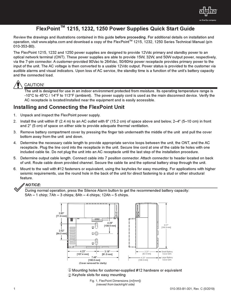
Alpha CXPS-C Quick start guide

Technical Guide 9400001-J1
Effective: 11/2018
CXPS-C
Centralized Power Plant
Alpha Technologies Ltd.


CXPS-C
Centralized Power Plant
For technical support, contact Alpha Technologies:
Canada and USA: 1-888-462-7487
International: +1-604-436-5547
Copyright
Copyright © 2018 Alpha Technologies Ltd. All rights reserved. Alpha is a registered trademark of Alpha Technolo-
gies.
No part of this documentation shall be reproduced, stored in a retrieval system, translated, transcribed, or transmit-
ted in any form or by any means manual, electric, electronic, electromechanical, chemical, optical, or otherwise
without prior explicit written permission from Alpha Technologies.
This document, the software it describes, and the information and know-how they contain constitute the proprietary,
confidential and valuable trade secret information of Alpha Technologies, and may not be used for any unauthorized
purpose, or disclosed to others without the prior written permission of Alpha Technologies.
The material contained in this document is for information only and is subject to change without notice. While
reasonable efforts have been made in the preparation of this document to assure its accuracy, Alpha Technologies
assumes no liability resulting from errors or omissions in this document, or from the use of the information contained
herein. Alpha Technologies reserves the right to make changes in the product design without reservation and with-
out notification to its users.
Alpha shall not be held liable for any damage or injury involving its enclosures, power
supplies, generators, batteries, or other hardware if used or operated in any manner or
subject to any condition inconsistent with its intended purpose, or if installed or oper-
ated in an unapproved manner, or improperly maintained.
Photographs contained in this manual are for illustrative purposes only. These photo-
graphs may not match your installation.
NOTE:
Operator is cautioned to review the drawings and illustrations contained in this manual
before proceeding. If there are questions regarding the safe operation of this powering
system, contact Alpha Technologies or your nearest Alpha representative.
NOTE:
NOTE:


Table of Contents
1. Safety....................................................................................................................................6
1.1 Safety Symbols .......................................................................................................................... 6
1.2 General Warnings and Cautions ................................................................................................ 6
1.3 Electrical Safety ......................................................................................................................... 7
1.4 Battery Safety ............................................................................................................................ 7
2. Introduction ...........................................................................................................................8
2.1 Product Overview....................................................................................................................... 8
2.2 Part Numbers and List Options.................................................................................................. 8
3. Specications........................................................................................................................9
4. Features..............................................................................................................................12
4.1 Power Bays.............................................................................................................................. 13
4.2 Rectier Modules ..................................................................................................................... 15
4.3 Distribution Bays ...................................................................................................................... 16
4.4 DC Inter-bay Copper................................................................................................................ 25
4.5 Cordex HP Controller ............................................................................................................... 27
4.6 External Peripherals................................................................................................................. 28
5. Pre-Installation Preparation ................................................................................................31
5.1 Site Selection ........................................................................................................................... 31
5.2 Tools and Test Equipment ........................................................................................................ 32
5.3 Floor Loading ........................................................................................................................... 32
6. Inspection............................................................................................................................33
6.1 Packing Materials..................................................................................................................... 33
6.2 Check for Damage ................................................................................................................... 33
6.3 General Receipt of Shipment................................................................................................... 33
7. Frame Installation ...............................................................................................................34
7.1 Floor Drilling for Standard Anchoring ....................................................................................... 34
7.2 Placing and Securing the Bays ................................................................................................ 35
7.3 Securing Adjacent Bays ........................................................................................................... 36
7.4 Installing the Inter-bay DC Bus Work between Adjacent Frames ............................................ 37

7.5 Connecting the Shunt and Inter-Bay Signal Cables................................................................. 39
7.6 Mounting the Optional External Return Bar ............................................................................. 44
7.7 Battery Installation ................................................................................................................... 45
7.8 Battery Maintenance Report .................................................................................................... 47
8. Wiring..................................................................................................................................48
8.1 Installation Notes ..................................................................................................................... 48
8.2 Connecting the Frame and Reference Grounds ...................................................................... 50
8.3 AC Supply for the Rectiers ..................................................................................................... 51
8.4 Distribution ............................................................................................................................... 54
9. Installing Standalone Power and Distribution Bays ............................................................57
9.1 Standalone Power Bay ............................................................................................................ 57
9.2 Standalone Distribution Bay..................................................................................................... 58
10. System Startup .................................................................................................................59
10.1 Check System Connections................................................................................................... 59
10.2 Verify AC and Power the Rectier Shelf................................................................................. 59
10.3 Check Battery Polarity and Connect ..................................................................................... 59
10.4 Final Conguration and Test .................................................................................................. 59
10.5 Shelf ID Connection ............................................................................................................... 60
11. Test and Commissioning Overview ...................................................................................61
11.1 System ................................................................................................................................... 61
11.2 Battery.................................................................................................................................... 61
11.3 Documentation ....................................................................................................................... 61
12. Maintenance .....................................................................................................................62
12.1 Rectiers ................................................................................................................................ 62
12.2 Batteries................................................................................................................................. 62
12.3 Controller Lithium Battery Replacement ................................................................................ 62
13. Warranty Statement and Service Information ...................................................................63
14. Acronyms and Denitions .................................................................................................64
15. Certication.......................................................................................................................65

List of Figures
Figure 1 — CXPS-C Centralized Power Plant Basic System ........................................................... 8
Figure 2 — Basic Power System .................................................................................................... 12
Figure 3 — Stand-alone Power Bay showing DC Charge Buses ................................................... 14
Figure 4 — Top View of Horizontal Inter-bay Busbars .................................................................... 14
Figure 5 — 4.0kW Rectier Front Panel LEDs ............................................................................... 15
Figure 6 — 12kW (3-phase) Rectier Front Panel LEDs ................................................................ 15
Figure 7 — Distribution Panel Options............................................................................................ 17
Figure 8 — 4 Position TPL.............................................................................................................. 18
Figure 9 — 12x 1 Position High Capacity Breaker.......................................................................... 18
Figure 10 — 6x 2 Position High Capacity Breaker.......................................................................... 19
Figure 11 — 4x 3 Position High Capacity Breaker.......................................................................... 19
Figure 12 — 3x 4 Position High Capacity Breaker.......................................................................... 20
Figure 13 — 2x 5 Position High Capacity Breaker.......................................................................... 20
Figure 14 — 2x 6 Position High Capacity Breaker.......................................................................... 21
Figure 15 — 4x2 & 4x1 Position High Capacity Breaker ................................................................ 21
Figure 16 — 18 Position Bullet Breaker.......................................................................................... 22
Figure 17 — 18 Position Bullet Breaker Return .............................................................................. 22
Figure 18 — Distribution Bay—DC Distribution Bus ....................................................................... 23
Figure 19 — Distribution Shunts ..................................................................................................... 24
Figure 20 — Inter-bay DC Connections.......................................................................................... 25
Figure 21 — External Battery Return Ground Bar .......................................................................... 26
Figure 22 — Cordex CXC HP Controller ........................................................................................ 27
Figure 23 — LCD Color Touchscreen Display ................................................................................ 27
Figure 24 — L-ADIO I/O Peripheral ................................................................................................ 28
Figure 25 — 6I-ADIO Peripheral..................................................................................................... 29
Figure 26 — Redundant Input Power Module................................................................................. 30
Figure 27 — Shelf/Bay ID ............................................................................................................... 30
Figure 28 — Base Dimensions and Mounting Holes ...................................................................... 34
Figure 29 — Securing Power System to Concrete Floor ................................................................ 35

59400001-J1 Rev F
Figure 30 — Bolting Adjacent Bays Together ................................................................................. 36
Figure 31 — Example of Installed Inter-bay Buswork..................................................................... 38
Figure 32 — Shunt Connections..................................................................................................... 39
Figure 33 — Inter-bay Wiring Harness ........................................................................................... 39
Figure 34 — CAN OUT Port Terminator.......................................................................................... 40
Figure 35 — Controller, CAN Bus cabling 4.0kW Power Bay ......................................................... 40
Figure 36 — Controller and Shelf/Bay ID, CAN Bus and Shelf ID cabling...................................... 41
Figure 37 — CAN Bus Termination 4.0kW...................................................................................... 42
Figure 38 — CAN IN/CAN OUT Connection 4.0kW ....................................................................... 42
Figure 39 — Battery Disconnect Connections ................................................................................ 43
Figure 40 — External Battery Return Bar Kit .................................................................................. 44
Figure 41 — Battery Installation...................................................................................................... 45
Figure 42 — Battery Temperature Probes ...................................................................................... 46
Figure 43 — Battery Return Busbars, Frame Ground and Battery Return Reference.................... 50
Figure 44 — AC Distribution ........................................................................................................... 51
Figure 45 — Pre Wired 8-feed AC Panel - 3 Phase, 3 Wire 208/480 Vac ...................................... 52
Figure 46 — Terminal Blocks for 8-feed 3 wire 208/480Vac input .................................................. 53
Figure 47 — Terminal Blocks for 16-feed 208/480Vac input ........................................................... 53
Figure 48 — Terminal Blocks for 6-feed 480Vac input .................................................................... 53
Figure 49 — High Capacity Breaker Panel Alarm Wiring................................................................ 54
Figure 50 — External Battery Return Bar Wiring ............................................................................ 55
Figure 51 — Customer Connections Spacing................................................................................. 56
Figure 52 — Example of a Single Bay with Two Rectier Shelves. ................................................ 60

9400001-J1 Rev F
6
1. Safety
SAVE THESE INSTRUCTIONS: This manual contains important safety instructions that must
be followed during the installation, servicing, and maintenance of the product. Keep it in a safe place. Review the
drawings and illustrations contained in this manual before proceeding. If there are any questions regarding the safe
installation or operation of this product, contact Alpha Technologies or the nearest Alpha representative.
1.1 Safety Symbols
To reduce the risk of injury or death, and to ensure the continued safe operation of this product, the following sym-
bols have been placed throughout this manual. Where these symbols appear, use extra care and attention.
The use of ATTENTION indicates specic regulatory/code requirements that may affect the
placement of equipment and/or installation procedures.
WARNING!
WARNING presents safety information to PREVENT INJURY OR DEATH to personnel.
Warnings are indicated by a shock hazard icon, the word WARNING, and a rule beneath
which the information appears.
WARNING!
You must read and understand the following warnings before installing the enclosure
and its component. Failure to do so could result in personal injury or death.
CAUTION!
CAUTION indicates safety information intended to PREVENT DAMAGE to material or
equipment. Cautions are designated with a yellow warning triangle, the word CAUTION,
and a rule beneath which the information appears.
NOTE:
A NOTE provides additional information to help complete a specic task or procedure.
Notes are designated with a checkmark, the word NOTE, and a rule beneath which the
information appears
HOT!
The use of HOT presents safety information to PREVENT BURNS to the technician or
user.
1.2 General Warnings and Cautions
• Read and follow all instructions included in this manual.
• Only trained personnel are qualified to install or replace this equipment and its components.
• Use proper lifting techniques whenever handling equipment, parts, or batteries.

79400001-J1 Rev F
1.3 Electrical Safety
WARNING!
WARNING!
Before working with any live battery or power system, follow these precautions:
a. Remove all metallic jewelry, such as watches, rings, metal rimmed glasses, or necklaces.
b. Wear safety glasses with side shields at all times during the installation.
c. Use OSHA approved insulated hand tools. Do not rest tools on top of batteries.
Lethal voltages are present within the power system. Always assume that an electrical
connection or conductor is energized. Check the circuit with a voltmeter with respect to
the grounded portion of the enclosure (both AC and DC) before performing any installa-
tion or removal procedure.
Follow battery manufacturer’s safety recommendations when working around battery
systems. Do not smoke or introduce an open ame when batteries (especially vented
batteries) are charging. When charging, batteries vent hydrogen gas, which can explode.
WARNING!
Hazardous voltages are present at the input of power systems. The DC output from rec-
tiers and batteries, though not dangerous in voltage, has a high short-circuit current
capacity that may cause severe burns and electrical arcing.
• Do not work alone under hazardous conditions.
• A licensed electrician is required to install permanently wired equipment. Input voltages can range up to
240 Vac. Ensure that the utility power is disconnected and locked out before performing any installation
or removal procedure.
• Ensure that no liquids or wet clothes come into contact with internal components.
• Hazardous electrically live parts inside this unit are energized from the batteries even when the AC input
power is disconnected.
• The enclosure which contains the DC or AC power system must remain locked at all times, except
when authorized service personnel are present.
• Always assume electrical connections or conductors are live. Turn off all circuit breakers and double-
check with a voltmeter before performing installation or maintenance.
•
• At high ambient temperature conditions, the internal temperature can be hot so use caution when
touching the equipment.
1.4 Battery Safety
• Never transport an enclosure with batteries installed. Batteries must ONLY be installed after the enclosure has
been securely set in place at its permanent installation location. Transporting the unit with batteries installed may
cause a short circuit, fire, explosion, and/or damage to the battery pack, enclosure and installed equipment.
• Servicing and connection of batteries must be performed by, or under the direct supervision of, person-
nel knowledgeable of batteries and the required safety precautions.
• Batteries contain or emit chemicals known to cause cancer and birth defects or other reproductive
harm. Battery post terminals and related accessories contain lead and lead compounds. Wash your
hands after handling batteries.
• Batteries are hazardous to the environment and should be disposed at a recycling facility. Consult the battery
manufacturer for recommended local authorized recyclers.
9400001-J1 Rev F
8
2. Introduction
2.1 Product Overview
The CXPS-C power system provides high capacity DC power for large communications applications—central offices,
mobile switching centers, data center and cable headend facilities. The main source of power for the power system
is commercial AC power, which is converted to DC by the modular switched mode rectifiers. It is a fully automatic
system, which provides float and equalize capability for the batteries.
The basic system consists of two bays and
inter-bay copper busbars (Figure 1). The
Power bay converts AC to fully regulated
and filtered 48Vdc power, which is fed
through a load shunt to the Distribution Bay.
The system can be expanded from the
center-out to a full 12,000A capacity system
using the CXC HP controller.
The system is configurable in 4000A, 8000A
and 12000A (CXC HP) capacity.
2.2 Part Numbers and List
Options
The system offers several advanced fea-
tures with add-on list options. These list
options can be included by the customer
at time of ordering or can be added in the
future; e.g., additional Cordex HP rectifi-
ers. For more information, see the ordering
guide on the Alpha website.
Figure 1 — CXPS-C Centralized Power Plant Basic System

99400001-J1 Rev F
3. Specifications
Table A — Specications for CXPS-C Power System
Electrical
DC Output Voltage 48V
AC Input Voltage
6 feeds: 4.0kW Rectier Shelf
277/480Vac, 60Hz (3 Phase - 3 Wire + N + PE)
12kW Rectier Shelf
480Vac, 60Hz (3 Phase - 3 Wire + PE)
8 feeds: 4.0kW Rectier Shelf
208Vac, 60Hz (3 Phase - 3 Wire + PE)
277/480Vac, 60Hz (3 Phase - 3 Wire + N + PE)
12kW Rectier Shelf
480Vac, 60Hz (3 Phase - 3 Wire + PE)
16 feeds: 4.0kW Rectier Shelf
208Vac, 60Hz (3 Phase - 3 Wire + PE)
277/480Vac, 60Hz (3 Phase - 3 Wire + N + PE)
12kW Rectier Shelf
480Vac, 60Hz (3 Phase - 3 Wire + PE)
Nominal Rectier Voltage 4.0kW: 208 to 277Vac
12.0kW 480Vac
Max. Bus Capacity 4,000A, 8,000A, or 12,000A (CXC HP)
2,000A or 4,000A per power bay
6,000A per distribution bay
Number of negative landings
for batteries (rectier side of
the shunt)
Single Power bay: 11 X 1/2" on 1 3/4" centers or 24 x 3/8" on 1" centers
Each Additional Power bay: 14 X 1/2" on 1 3/4" centers or 14 x 3/8" on 1" centers
Number of landings on the
load side of the shunt to feed
unfused power to remote
distribution
Single Distribution Bay: 14 X 1/2" on 1 3/4" centers or 11 X 3/8" on 1" centers
Each Additional Distribution Bay: 14 X 1/2" on 1 3/4" centers or 14 X 3/8" on 1" centers
Mechanical
Enclosure 1.095 mm (14 gauge) steel
Mounting Standard 23" relay rack (ush rack mount) in box bay
Dimensions, H x W x D 213 x 71 x 71 cm (84 x 28 x 28 in)
Weight Power bay (no rectiers): approximately 272 kg (600 lb)
Distribution bay: 432 kg (950 lb) (lled with TPL fuses)
Environmental
Temperature 0 to + 40°C (32 to 104°F)
Relative Humidity 0 to 95% RH non-condensing
Elevation -500 to 2000 m (-1640 to 6562 ft)
Agency compliance
CSA C22.2 No. 60950-1-07
UL UL 60950-1, Second Edition
EMC FCC CFR47 Part 15 Class A; ICES-003
NEBS Level 3

9400001-J1 Rev F
10
Table B — Related Components
Cordex HP 4kW rectier
See the Cordex HP 4kW rectier datasheet for more detailed information.
Cordex HP 12kW rectier
See the Cordex HP 12kW rectier datasheet for more detailed information.
System level alarms/controls
Alarms/control parameters are user-programmable through built-in digital supervisory unit.
See CXC HP datasheet for detailed information on alarms and controls.
Indicators:
LCD with touch screen
System OK (green LED)
System minor alarm (yellow LED)
System major alarm (red LED)
Load disconnect:
Panel based.
2000A per TPL fuse/Bolt-in breaker panel
600A pre plug-in bullet TLS/TPS fuse/CB panel
Alarm connections: 0.34 to 2.5 mm2(14 to 22AWG)
Smart peripheral modules
Shunt multiplexer 6 shunt inputs per module
External return bar
Mounting 2" Auxiliary framing (customer supplied)
Termination
With 3 horizontal bars:
202 sets of 1/2" holes on 1 3/4" centers or
202 sets of 3/8" holes on 1" centers
Unit capacity per bay 4000A
Ultimate capacity 12,000A (3 bay limit)
Table C — Distribution, Panels
Panel Type/
Busbar
Quantity/Rating Max Rating
per Panel
Output Termination
TPL Fuses 61 to 800A (up to 24
per distribution bay)
2000A 2 hole 1/2" dia. on 1 3/4" centers or
2 hole 3/8" dia. on 1" centers
allows for dual cable landing back to back
Bolt-in breakers 1 pole up to 250A
2 pole 300 to 400A
3 pole 500 to 700A
4 pole 800A
5 pole 1000A
6 pole 1200A
2000A 2 hole 3/8" dia. on 1" center and 1/2" dia. on 1 3/4"
center
12x 1 Position 2 hole, 3/8" dia. on 1" center only
Plug-in bullet
breakers
1 pole up to 100A
2 pole 110 to 200A
3 pole 225 to 300A
600A 1 pole: 2 hole 1/4" dia. on 5/8" centers
2 and 3 pole: 2 hole, 3/8" dia. on 1 centers
(100A and 125A breakers/fuses need one breaker
space)
Plug-in TPS/TLS
fuse holders
Up to 125A, 18 per panel 600A 2 hole 1/4" dia. on 3/8" centers

119400001-J1 Rev F
Table D — Distribution, Busbars
Number of negative landings
for batteries (rectier side of
the shunt)
Single power bay: 11 X 1/2" on 1 3/4" centers or 24 x 3/8" on 1" centers
Each additional power bay: 14 X 1/2" on 1 3/4" centers or 14 x 3/8" on 1" centers
Number of landings on the
load side of the shunt to feed
unfused power to remote
distribution
Single distribution bay: 14 X 1/2" on 1 3/4" centers or 11 x 3/8" on 1" centers
Each additional power bay: 14 X 1/2" on 1 3/4" centers or 14 x 3/8" on 1" centers
Internal return bar Overhead bus ground, 24 sets of 2 hole, 1/2" dia. on 1 3/4" centers or 3/8" dia. on 1"
centers (basic one power plus one distribution bay); 14 additional sets per additional
rectier or distribution bay

9400001-J1 Rev F
12
4. Features
The basic system consists of two bays and inter-bay copper busbarss. The power bay converts AC to fully regulated
and filtered DC power, which is fed through a load shunt to the second bay for distribution.
Basic power system
• 1x 4000A power bay (8 shelves) or 1x 2000A power bay (4 shelves)
• 1x 6000A distribution bay
• System controller
Expandable to include
• 1x or more additional 4000A power bay (8000A or 12000A system capacity)
• 1x or more additional 2000A power bay (4000A, 6000A, 8000A, 10000A or 12000A system capacity)
• 1x or more additional 6000A distribution bays (12000A distribution capacity)
Distribution bayPower bay
Controller
AC Distribution
Assembly
8x CXRF 48V-4kW
shelves
or
8x CXRF-HP 48V-
12kW/480 shelves
Figure 2 — Basic Power System

139400001-J1 Rev F
4.1 Power Bays
4.1.1 Cordex HP System Controller
The Cordex HP system controller, mounted in the primary power bay, provides easy access to controls and display
status. The controller provides comprehensive setup, control, monitoring and communication for Alpha DC power
systems.
Controller features include the following:
• Designed to communicate directly with HP rectifiers
• Includes battery temperature compensation charging
• Battery performance diagnostics
• Provides local and remote communications
• User definable alarms
• Daily logging of power system events and system statistics
• Active low voltage disconnect (LVD)
See the controller manual shipped with your order for detailed information.
4.1.2 Cordex HP Rectifier Shelves
A 4000A power bay has eight rectifier shelves and a 2000A bay has four rectifier shelves. Each rectifier shelf can
hold up to six Cordex HP 4kW rectifier modules or two 12kW/480 rectifier modules.
A Cordex HP 4.0kW rectifier supplies a nominal output of 74A at 54Vdc and the 12kW/480 rectifier supplies 222A
at 54Vdc nominal. Rectifier specifications are included in the Cordex HP rectifier manual included with the system
documentation package.
The controller provides central control of the rectifiers’ output level, load sharing, temperature compensation, low
voltage disconnect on the distribution bay and alarm reports. A CAN bus cable is wired or daisy-chained to each
rectifier shelf for communication with the controller.
4.1.3 AC Termination Wiring
The required input voltage depends on the rectifier options chosen at the time of ordering. The AC distribution as-
sembly at the top of each power bay provides front access AC overhead termination.
A split AC terminal box allows for feeds from two separate sources. Eight feed is standard; six or sixteen feed is an
option. See the specifications in Chapter 3 on page 9.
4.1.4 Standalone or Add-on Power Bays
A standalone power bay can replace multiple bays with less capacity in an existing power system or as an add-on to
upgrade the capacity of an installed CXPS-C power system.

9400001-J1 Rev F
14
4.1.5 Power Bay DC Charge Buses
Each standalone power bay has two vertical charge bars con-
necting all return terminals and all negative terminals of the recti-
fier shelves (Figure 3). These busbars are rated for the maximum
current supplied by the rectifier shelves.
In a multi-bay power system, the return vertical busbar connects
to an inter-bay return bar located across the top of the power and
distribution bays. Similarly the -48V vertical busbar connects to
an inter-bay -48V busbar, which terminates at the system shunt
located in the distribution bay.
Figure 4 shows a top view of the horizontal busbars between a
power bay and two distribution bays.
Return (+)-48V
FRONT
REAR
Power BayDistribution Bay
Inter-bay return busbar
Inter-bay -48V busbar
Distribution Bay
BACK
FRONT
Shunt
Figure 3 — Stand-alone Power Bay showing DC
Charge Buses
Figure 4 — Top View of Horizontal Inter-bay Busbars

159400001-J1 Rev F
4.2 Rectifier Modules
The rectifier modules are "hot swappable" allowing for quick replacement and easy maintenance of the system.
(They can be inserted or removed from the shelf without removing AC power or shutting down the entire system.)
4. 2 .1 Rectifier Alarms and LEDs
Rectifier status, such as mains OK, Minor and Major alarms, display on the rectifier front panel.
A rectifier Major alarm indicates, the module has shut down due to a critical fault.
A rectifier Minor alarm indicates the module has a non-critical alarm, however, it has not shut down.
See the Cordex HP rectifier manual included with the system documentation package for detailed information.
LEDs
LEDs
Figure 5 — 4.0kW Rectifier Front Panel LEDs
Figure 6 — 12kW (3-phase) Rectifier Front Panel LEDs

9400001-J1 Rev F
16
4.3 Distribution Bays
Distribution bays are designed for high capacity distribution applications. Each distribution bay can be equipped with
a variety of different fuse/CB tier combinations, with or without LVLD option, as shown in Table E and Figure 7.
Table E — Distribution Options per Bay
Tier Type Rating Max Rating
per Panel
Number of Positions per Bay
TPL fuses 100-800A 2000A 4 fuse holders per tier
Max 6 fuse tiers per bay
Bolt-in breakers
(high capacity)
1 pole 100 to 250A 2000A 12 breaker poles per tier
Max 6 panels per bay
2 pole 300 to 400A
3 pole 500 to 700A
4 pole 800A
5 pole 1000A
6 pole 1200A
Plug-in bullet breakers 1 pole up to 100A 600A 18 breaker poles per tier
Max 12 tiers per bay
(100A and 125A breakers/fuses need one
breaker space between breaker and breaker
beside it)
2 pole 110 to 200A
3 pole 225 to 300A
Plug-in bullet TPS/TLS
fuse holders Up to 125A 600A 18 fuse holders per tier
Max 12 fuse tiers per bay
(100A and 125A breakers/fuses need one
breaker space between breaker and breaker
beside it)

179400001-J1 Rev F
Bullet breaker tier
LVD inhibit
High capacity breaker tier
TPL fuse tiers
Distribution panel
alarm indicator
Figure 7 — Distribution Panel Options
Table of contents
Other Alpha Power Supply manuals

Alpha
Alpha FlexNet MPS48-7C User manual

Alpha
Alpha Lectro 60V User manual

Alpha
Alpha FlexPoint 1215 User manual

Alpha
Alpha FlexPoint 1208-F User manual

Alpha
Alpha BROADBAND UPS XM3.1-HP User manual

Alpha
Alpha NPS-W1 User manual

Alpha
Alpha DOCSIS DM31 User manual

Alpha
Alpha APP60S User manual

Alpha
Alpha HDN 300 User manual

Alpha
Alpha APP 9005C User manual
Popular Power Supply manuals by other brands

Zennio
Zennio ALLinBOX 88 Technical documentation

Akyga
Akyga AK-L1-100 user manual

Belden
Belden Hirschmann PC150/36V/48V-IP67 Description and operating instructions

Puls
Puls MiniLine ML100.109 installation manual

Matsusada Precision
Matsusada Precision AK Series instruction manual

Terraneo
Terraneo 336010 instruction sheet