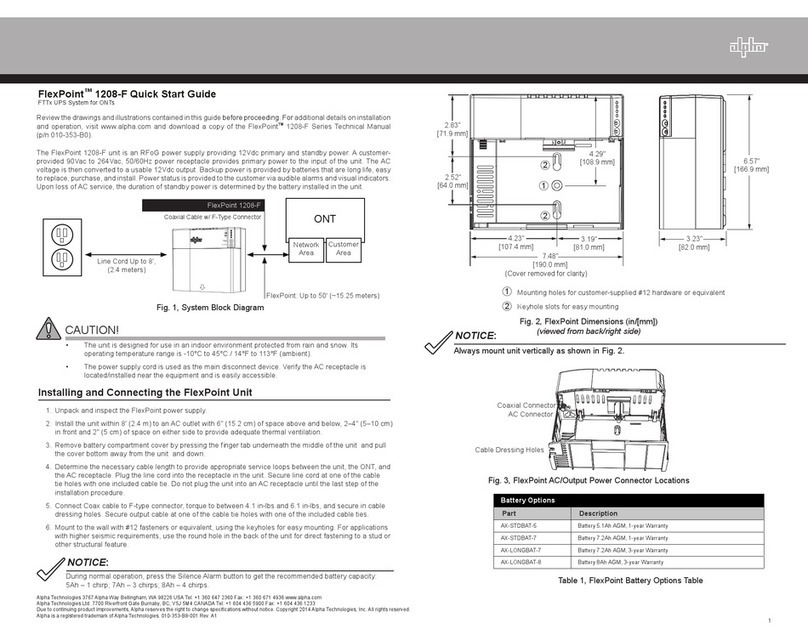
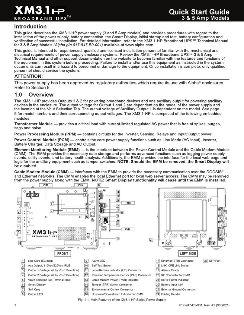
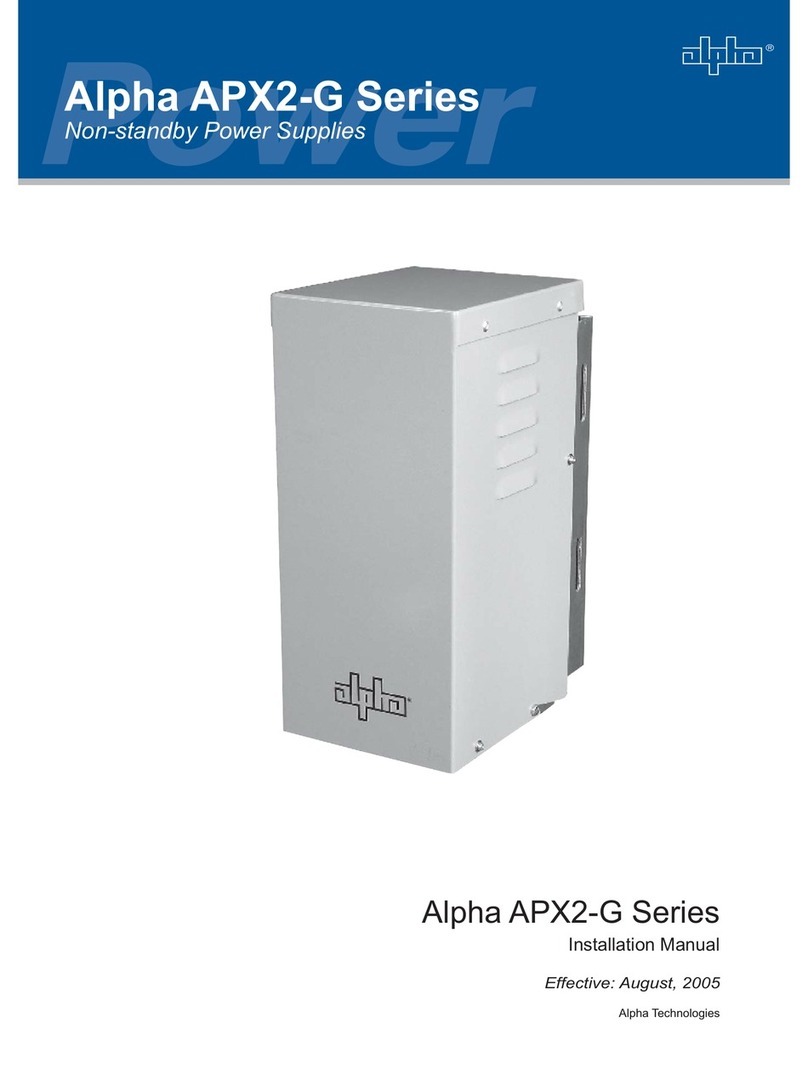
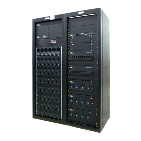
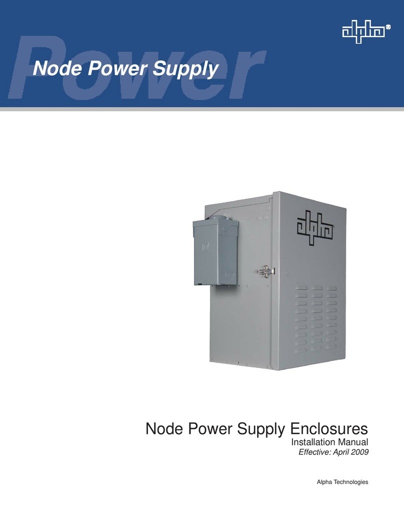
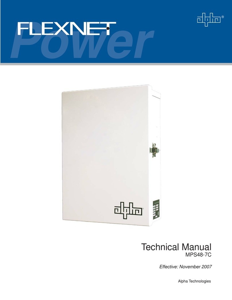
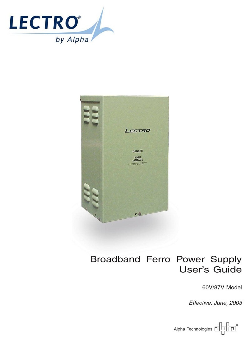
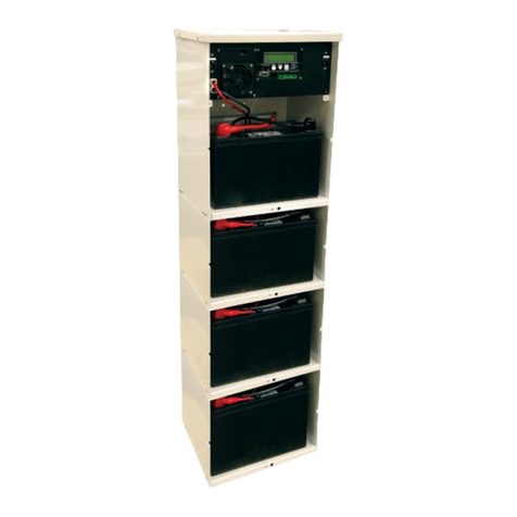
Alpha NPS-W1 User manual

Node Power Supply Enclosure
Installation Manual
Eective: November 2018

2031-295-B0-001, Rev. B (11/2018)
Safety Notes
Alpha considers customer safety and satisfaction its most important priority. To reduce the risk of injury or death and to
ensure continual safe operation of this product, certain information is presented dierently in this manual. Alpha tries to
adhere to ANSI Z535 and encourages special attention and care to information presented in the following manner:
The following sections contain important safety information that must be followed during the installation and maintenance
of the equipment and batteries. Read all of the instructions before installing or operating the equipment, and save this
manual for future reference.
There may be multiple warnings associated with the call out. Example:
ATTENTION provides specic regulatory/code requirements that may aect the placement of equipment and /or
installation procedures.
ATTENTION:
NOTICE provides additional information to help complete a specic task or procedure.
NOTICE:
ELECTRICAL HAZARD WARNING provides electrical safety information to PREVENT INJURY OR DEATH
to the technician or user.
WARNING! ELECTRICAL HAZARD
FUMES HAZARD WARNING provides fumes safety information to PREVENT INJURY OR DEATH to the
technician or user.
WARNING! FUMES HAZARD
FIRE HAZARD WARNING provides ammability safety information to PREVENT INJURY OR DEATH to the
technician or user.
WARNING! FIRE HAZARD
This WARNING provides safety information for both Electrical AND Fire Hazards.
WARNING! ELECTRICAL AND FIRE HAZARD
CAUTION provides safety information intended to PREVENT DAMAGE to material or equipment.
CAUTION!
GENERAL HAZARD WARNING provides safety information to PREVENT INJURY OR DEATH to the
technician or user.
WARNING! GENERAL HAZARD
LASER RADIATION WARNING provides safety information with respect to laser radiation and optical bers.
WARNING! LASER RADIATION

3031-295-B0-001, Rev. B (11/2018)
Node Power Supply Enclosure
Installation Manual
031-295-B0-001, Rev. B
Eective November 2018
Alpha Technologies, Inc.
Disclaimer
Images contained in this manual are for illustrative purposes only. These images may not match your installation.
Operator is cautioned to review the drawings and illustrations contained in this manual before proceeding. If there are
questions regarding the safe operation of this powering system, please contact Alpha Technologies or your nearest Alpha
representative.
Alpha shall not be held liable for any damage or injury involving its enclosures, power supplies, generators, batteries or
other hardware if used or operated in any manner or subject to any condition not consistent with its intended purpose or is
installed or operated in an unapproved manner or improperly maintained.
Contact Information
Sales information and customer service in USA (7AM to 5PM, Pacic Time) .............................................1 800 322 5742
Complete technical support in USA (7AM to 5PM, Pacic Time or 24/7 emergency support) ....................1 800 863 3364
Sales information and technical support in Canada ....................................................................................1 888 462 7487
Website ........................................................................................................................................................www.alpha.com
Introduction
This manual describes the Node Power Supply Enclosure (NPS) and relevant installation information and is intended for
the installers of the enclosure. The installers must be familiar with enclosure installation as well as system grounding and
the safety issues related to lasers and ber optic cabling.
Audience
This guide is intended for experienced installers familiar with the mechanical and electrical requirements of ber optic
systems and qualied, licensed installation personnel. Review the support documentation on the website to become
familiar with the features and functions of the equipment in this system before proceeding. Failure to install and/or use this
equipment as instructed in the system documents can result in damage to the equipment. This system is only serviceable
by qualied personnel.
Trademark Information
Alpha® is a registered trademark of Alpha Technologies.
Revision History - P/N 031-295-B0-001
Version Date Description of Changes and New Features
A04 / 2009 Initial Release of Document
B 11/2018
The document format has been updated to match current style.
Specication and battery runtime tables have been amended.
References (text, graphics) to XM2 Power Supplies have been replaced with XM3.
Updated cooling fan connectivity illustration.
Added part number for right angle power cord at various locations throughout the manual.
Updated battery termination illustrations.

4031-295-B0-001, Rev. B (11/2018)
Contents
Important Safety Instructions...................................................................................... 6
Battery Maintenance Guidelines ................................................................................................................... 6
Electrical Safety ............................................................................................................................................ 6
Mechanical Safety ......................................................................................................................................... 7
Recycling and Disposal Instructions ............................................................................................................. 7
Battery Safety Notes ..................................................................................................................................... 7
Chemical Hazards ......................................................................................................................................... 7
Grounding and Earth Connection Notes.................................................................... 8
Safety Ground and Earth Connection ........................................................................................................... 8
1.0 Overview.................................................................................................................. 9
1.1 Node Power Supply (NPS) Enclosures ................................................................................................... 9
1.2 Specications ........................................................................................................................................ 10
1.3 Battery Runtime .................................................................................................................................... 11
1.4 Parts List ............................................................................................................................................... 13
2.0 Installation............................................................................................................. 14
2.1 Pole-mounted Conguration ................................................................................................................. 14
2.1.1 Installation on Wooden Pole .......................................................................................................... 15
2.1.2 Installation on Steel/Concrete Pole................................................................................................ 17
2.2 Rack-mounted Conguration ................................................................................................................ 19
2.2.1 Installation Procedure .................................................................................................................... 20
2.3 Wall-mounted Conguration .................................................................................................................. 21
2.3.1 Installation ...................................................................................................................................... 22
2.4 Floor-mounted Conguration ................................................................................................................ 23
2.4.1 Installation ...................................................................................................................................... 24
2.5 Connecting the Utility Power ................................................................................................................. 24
2.5.1 Service Power ................................................................................................................................ 25
2.6 Connecting the Coaxial Cable ............................................................................................................... 27
2.6.1 Coaxial Cable Surge Protector Installation Instructions................................................................. 27
2.6.2 Connecting the Service Power Inserter (SPI) ................................................................................ 28
2.6.3 Connecting the Service Power Inserter-RF (SPI-RF) .................................................................... 29
2.7 Battery Installation ................................................................................................................................. 30
2.7.1 Battery Installation Procedure........................................................................................................ 31
2.7.2 Battery Wiring Diagram .................................................................................................................. 32
2.7.3 Battery Terminal Connections ........................................................................................................ 33
2.8 Installing the XM3 Power Supply ......................................................................................................... 34
2.9 Cooling Fan Kit Installation .................................................................................................................. 35
2.10 Cooling Fan Kit Removal .................................................................................................................... 35
3.0 Populating the Cabinet and Turn-up Checklist.................................................. 36

5031-295-B0-001, Rev. B (11/2018)
Figures and Tables
Fig. 1-1 Node Power Supply Enclosures, pole-mount, rack-mount, and wall-mount congurations ................................9
Fig. 2-1 Dimensions and Features .................................................................................................................................14
Fig. 2-2 Wooden Pole Installation ..................................................................................................................................16
Fig. 2-3 Steel/Concrete Pole Installation ........................................................................................................................18
Fig. 2-4 Dimensions, Rack-mounted NPS Enclosure ....................................................................................................19
Fig. 2-5 Dimensions, Wall-mounted NPS Enclosure ......................................................................................................21
Fig. 2-6 Dimensions, Floor-mounted NPS Enclosure ....................................................................................................23
Fig. 2-7 120Vac Service Entrance Wiring .......................................................................................................................25
Fig. 2-8 520-R Receptacle Wiring ..................................................................................................................................26
Fig. 2-9 Surge Protector mounting locations ..................................................................................................................27
Fig. 2-10 Mounting locations for the standard SPI ...........................................................................................................28
Fig. 2-11 Cover Removal .................................................................................................................................................28
Fig. 2-12 Coaxial Cable Connection ................................................................................................................................28
Fig. 2-13 Mounting locations for the SPI-RF ....................................................................................................................29
Fig. 2-14 Battery Identication Label ................................................................................................................................30
Fig. 2-15 NPS Battery Wiring Diagram with 100GXL battery string .................................................................................32
Fig. 2-16 Hardware stack-up, Threaded Battery insert ....................................................................................................33
Fig. 2-17 Hardware stack-up, Threaded Battery insert with optional in-line fuse .............................................................33
Fig. 2-18 XM Series 3 Power Supply ...............................................................................................................................34
Fig. 2-19 Cooling fan installation conguration ................................................................................................................35
Table 1-1 Enclosure Specications ...................................................................................................................................10
Table 1-2 XM2-300HP Battery Runtime ............................................................................................................................ 11
Table 1-3 XM3-910HP 36V Battery Runtime (Congured for 90V Output) .......................................................................12
Table 1-4 XM3-615HP 36V Battery Runtime (Congured for 60V Output) .......................................................................12
Table 1-5 Parts List ...........................................................................................................................................................13
Table 2-1 Service Entrance Circuit Breaker Requirements ..............................................................................................24
This manual suits for next models
4
Table of contents
Other Alpha Power Supply manuals

Alpha
Alpha FlexPoint Series User manual

Alpha
Alpha Micro User manual

Alpha
Alpha APP60S User manual

Alpha
Alpha DOCSIS DM31 User manual

Alpha
Alpha FlexNet MPS48-7C User manual

Alpha
Alpha FlexNet MPS48-7C User manual

Alpha
Alpha HDN 300 User manual

Alpha
Alpha FlexPoint 1208-F User manual

Alpha
Alpha FlexPoint 1208-F User manual

Alpha
Alpha Lectro 60V User manual
Popular Power Supply manuals by other brands

Videx
Videx 520MR Installation instruction

Poppstar
Poppstar 1008821 Instructions for use

TDK-Lambda
TDK-Lambda LZS-A1000-3 Installation, operation and maintenance manual

TDK-Lambda
TDK-Lambda 500A instruction manual

Calira
Calira EVS 17/07-DS/IU operating instructions

Monacor
Monacor PS-12CCD instruction manual