Omron D6F Series User manual

MEMS Flow Sensor
MEMS Flow Sensor
User’s Manual
A286-E1-01
D6F-series

1 D6F-series MEMS Flaw Sensor User’s Manual (A286)
INDEX
1OUTLINE........................................................................................................................................ 2
2WHAT IS A FLOW SENSOR?....................................................................................................... 2
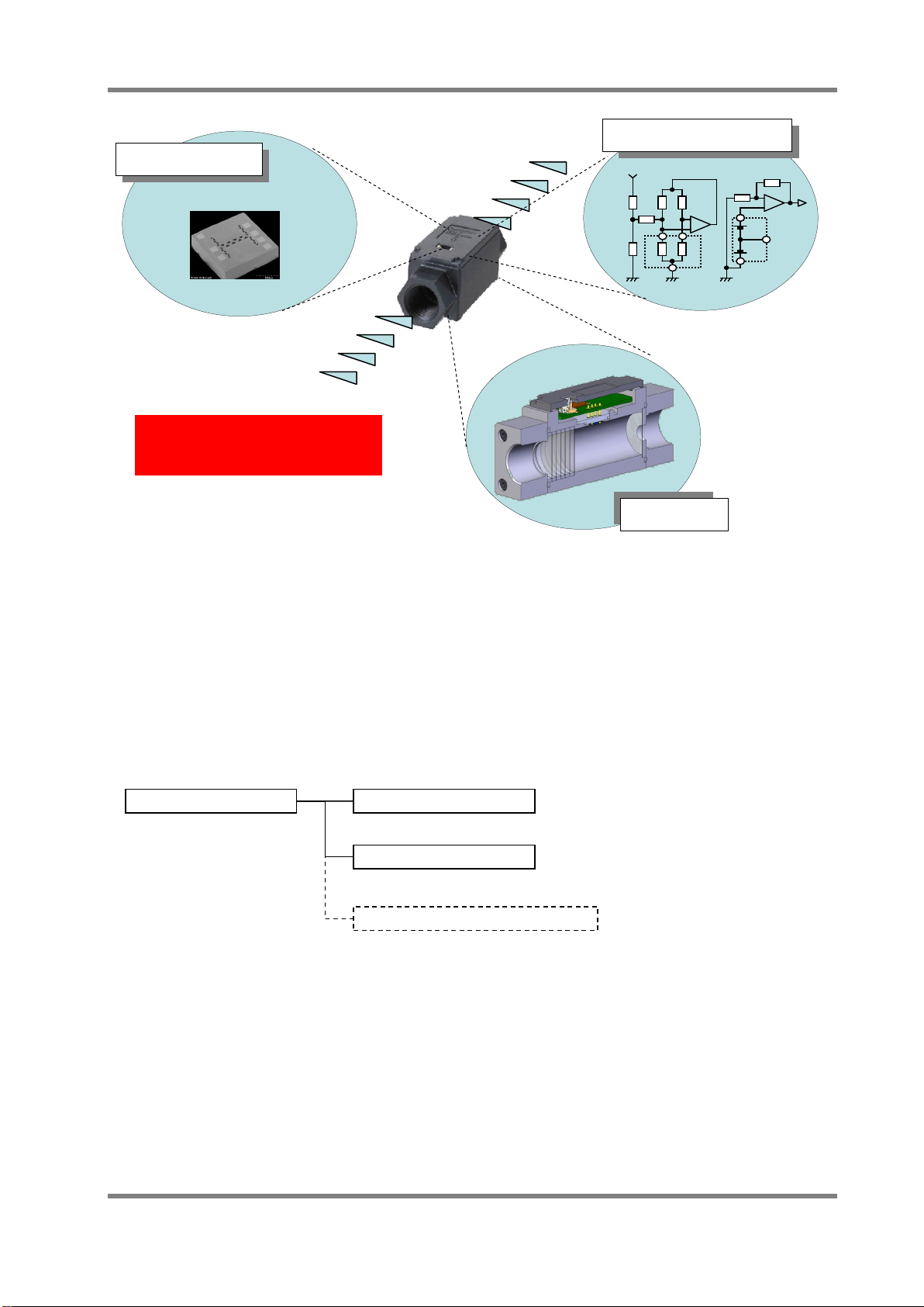
3STRUCTURE ................................................................................................................................. 2
3.1 BASIC COMPOSITION OF FLOW SENSORS.................................................................................... 2
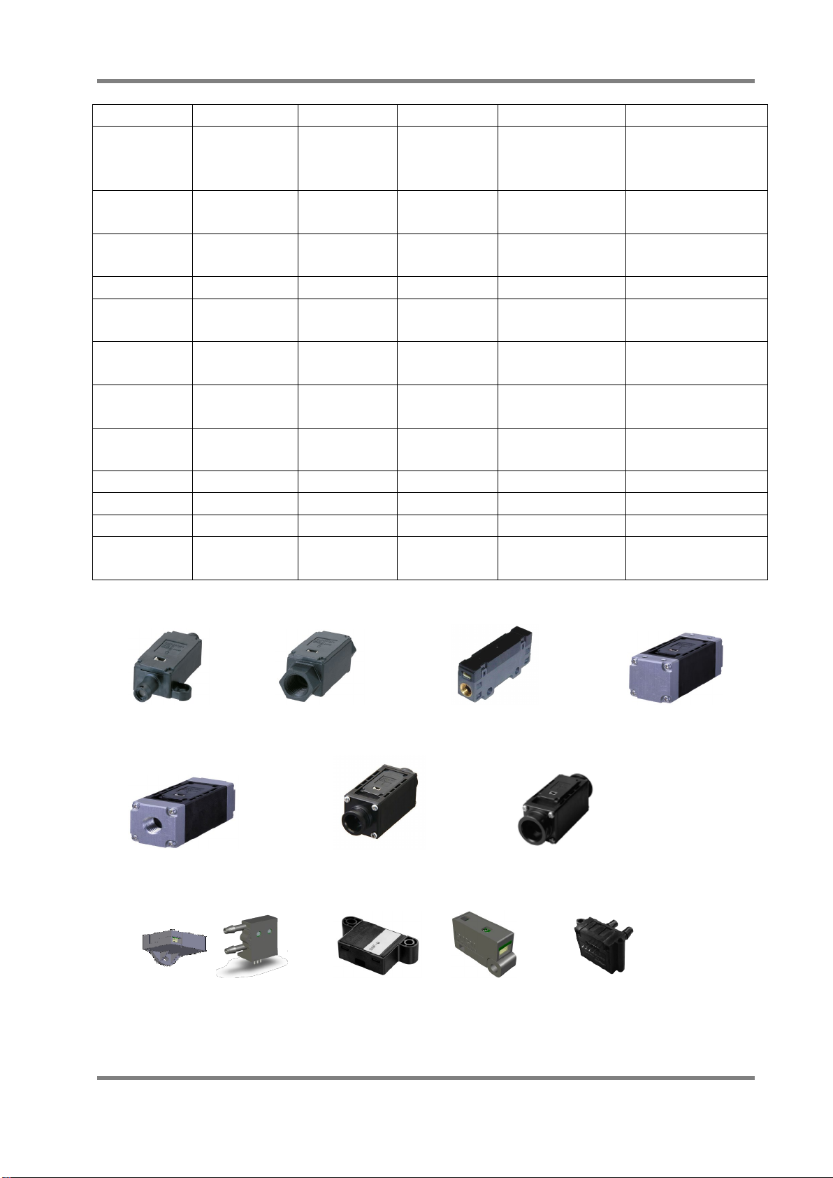
3.2 FLOW SENSOR PRODUCT LINEUP .............................................................................................. 3
4OPERATING PRINCIPLE.............................................................................................................. 4
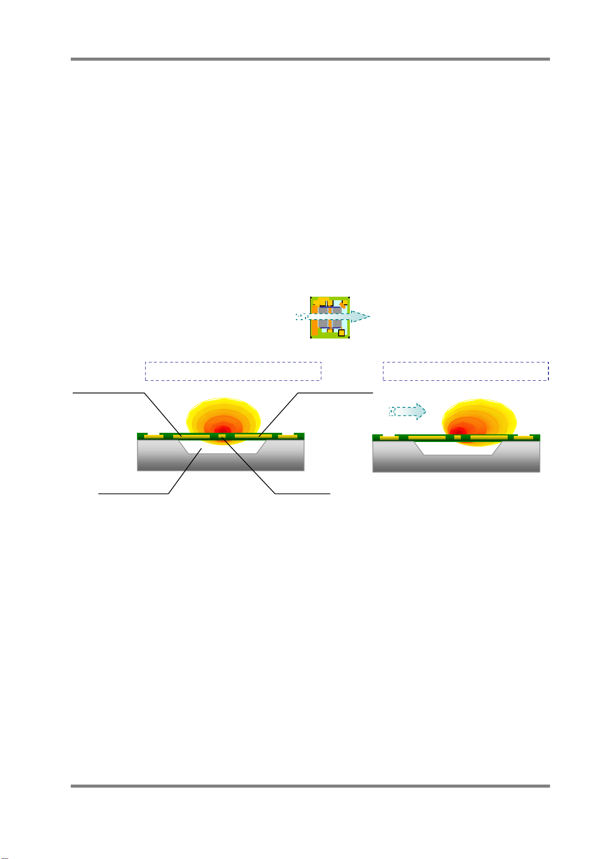
4.1 BASIC STRUCTURE OF MEMS FLOW SENSOR CHIP..................................................................... 4
4.2 DETECTING PRINCIPLE OF MASS FLOW SENSOR.......................................................................... 6
5PRODUCT FEATURES ................................................................................................................. 7
5.1 CHARACTERISTICS OF FLOW SENSORS ...................................................................................... 7
5.1.1 Detection range of flow sensors...................................................................................... 8
5.1.2 Output signal (operating characteristics)......................................................................... 8
5.1.3 Permission pressure performance .................................................................................. 9
5.1.4 Repeatability.................................................................................................................... 9
6USAGE OF FLOW SENSOR ........................................................................................................ 9
6.1 ELECTRICAL CONNECTION......................................................................................................... 9
6.2 PORT STYLE AND INSTALLATION METHOD.................................................................................. 10
6.2.1 Screw type..................................................................................................................... 10
6.2.2 Quick fastener type........................................................................................................ 10
6.2.3 Manifold mount type .......................................................................................................11
6.2.4 Bamboo type.................................................................................................................. 12
6.3 ATTENTION FOR PIPING AND CONNECTION ................................................................................ 13
6.3.1 Cleanup of the inflow gas .............................................................................................. 13
6.3.2 Stabilization.................................................................................................................... 13
6.3.3 Measurement of high flow ............................................................................................. 13
6.3.4 Consideration of the laminar flow.................................................................................. 14
6.4 THE INFLUENCE OF ENVIRONMENT ........................................................................................... 14
6.4.1 Temperature characteristics .......................................................................................... 15
6.4.2 The influence of dust ..................................................................................................... 15
6.4.3 The influence of pressure and temperature .................................................................. 16
6.4.4 The influence of the mounting direction ........................................................................ 16
6.4.5 Output changes in various gases.................................................................................. 17
6.4.6 The behavior in over flow rate range............................................................................. 17
6.4.7 The influence of humidity .............................................................................................. 17
6.5 APPLICATION EXAMPLE............................................................................................................ 18
7GLOSSARY ................................................................................................................................. 19
8WARRANTY AND LIMITED LIABILITY...................................................................................... 21

D6F-series MEMS Flaw Sensor User’s Manual (A286) 2
1 Outline
This application note explains the features, basic usage and some notices of OMRON MEMS
Flow Sensor (D6F series) before use.
2 What is a Flow Sensor?
A flow sensor is a sensor that detects the flow rate and flow velocity of a gas. In general, there are
various types of flow sensors, such as a propeller type, a float type, an ultrasonic type, a hot wire
type, and so on. OMRON flow sensors adopt a MEMS heat wire type, and have relatively excellent
characteristics in comparison with other types of flow sensors.
Table1. Various Types of Flow Sensor and Features
3 Structure
3.1 Basic composition of flow sensors
OMRON flow sensors are dedicated to gas, it can be used for detecting the mass flow of
various types of gases. The basic composition of flow sensors consist of a MEMS flow sensor
chip that can detect the flow rate, the amplifier circuit for amplifying sensor output and the
optimized flow path that is designed for each application by CAE (Computer Aided Engineering).
Optimizing these three compositions is very important because gas flow is a vector volume.
Type
Sensitivity
Response
Time
Pressure
Drop
Current
Consumption
Sensing
Size Element
Mechanical
Endurance
Propeller Float Ultrasonic Heat Wire MEMS
Heat Wire
OMRONConventional Sensors
Volumetric Flow Sensor Mass Flow Sensor
×
○
△
△
○
○
○
△
×
○
○
○
○
○
○
×
×
×
△
△
×
×
×
△
△
○
○
△
△
○

3 D6F-series MEMS Flaw Sensor User’s Manual (A286)
Fig. 1 Example of Internal Structure of Flow Sensor
3.2 Flow Sensor Product Lineup
OMRON’s flow sensor lineup consists of three categories, Mass flow sensors that output a flow
rate, Flow velocity sensors that output a flow velocity and Differential pressure sensors that can
detect a small pressure drop.
For more information about differential pressure sensors, please refer to the application notes of
MDMK-13-0196.
A flow sensor‘s shape and size will differ depending on the type of gas to be measured, the flow
rate, and the port style. Please refer to the datasheet at the following URL for more information.
http://www.omron.com/ecb/products/search/?cat=5&did=1&prd=mems-flow&lang=en
MEMS Flow Sensor
Mass Flow Sensor
Flow Velocity Sensor
D6F-V□/ -W□Series
D6F
-
PH Series
Differential Pressure Sensor
D6F
-□
A /
-□
AB /
-□
N /
-□
L /
-
P
□
Series
Driving / Amp. Circuit
MEMS
Flow Chip
Optimizing design of the three
compositional units is important.
Flow Path
(Sensing)(Heater / Output)

D6F-series MEMS Flaw Sensor User’s Manual (A286) 4
Table 2 Outline Specifications of D6F series
Series Name
Medium
Flow Rate Type Port Style Features
D6F-□A1 Air 1 ~2 lpm Mass Flow Bamboo Joint Compact Size
High Precision
Low Flow Rate
D6F-□N2 City gas*1 1 ~5 lpm Mass Flow Rc1/4 Screw Flammable Gas
Metal Body
D6F-02L2 LPG 2 lpm Mass Flow Rc1/4Screw Flammable Gas
Metal Body
D6F-03A Air 3 lpm Mass Flow M5 Screw High Response Time
D6F-□A5 Air 10 ~50 lpm Mass Flow Manifold Compact Size
High Flow Rate
D6F-□A6□ Air 10 ~50 lpm Mass Flow Rc1/4 Screw
NPT1/8 Screw
Compact Size
High Flow Rate
D6F-□□7 City gas*1
LPG / Air
2 ~50 lpm Mass Flow Quick Joint (P10) Quick Joint
D6F-□AB71 Air 30 ~70 lpm Mass Flow Quick Joint (P14) Quick Joint
Pulsation Reduction
D6F-P Air 0.1 ~1 lpm Mass Flow Bamboo / Manifold DSS*2 / Bidirectional
D6F-W Air 1 ~10 m/s Flow Velocity -DSS*2
D6F-V03A1 Air 3 m/s Flow Velocity -Low Cost of D6F-W
D6F-PH Air ±500 Pa Differential
Pressure
Bamboo Joint
Digital Output
Differential Pressure
Note. *1 : City Gas (Natural Gas) Standard:13A, *2 : DSS: Dust Segregation System
D6F-A1 D6F-□N2/-02L2 D6F-03A D6F-□A5
D6F-□□6 D6F-□□7 D6F-□AB7
D6F-P D6F-W D6F-V03A1 D6F-PH
Fig. 2 D6F Series
4 Operating principle
4.1 Basic structure of MEMS flow sensor chip
The basic structure of a MEMS flow sensor chip is shown in Fig.3. This sensor chip adopts a

5 D6F-series MEMS Flaw Sensor User’s Manual (A286)
mass flow sensing method by using heat wire. It has a heater in the center of the chip, and the
upstream thermopile (A) and the downstream thermopile (B) are located on either side of the
heater, the base thermo-scope near the thermopile is made by a semiconductor process. The
cavity is formed at the bottom of the heater and the thermopile arrays, so then it is possible to
detect the heat from the heater effectively.
Fig.3. Flow Sensor Chip Structure
Base Thermo-scope
Downstream
Thermopile B
Upstream
Thermopile A
Heater
Thin film
Cavity
Contact pad
Heater
Contact pad
Downstream
Thermopile B
Contact Pad
Base thermoscope
Upstream
Thermopile A

D6F-series MEMS Flaw Sensor User’s Manual (A286) 6
4.2 Detecting principle of mass flow sensor
As shown in Fig.4, the constant current is flowing to the heater at the center of the chip and the
heater becomes hot. When there is no flow, the heat distribution around the heater is symmetric,
so Vu and Vd of the electromotive force from both thermopiles will be equal.
On the other hand, when there is a flow of gas on the sensor surface, the heat source is biased
on the downstream side according to the flow of gas. The electromotive force of the downstream
thermopile will be larger than the upstream thermopile (Vd > Vu). The output difference between
the two thermopiles is approximately proportional to the square root of the mass flow rate of the
gas through the sensor surface. The output sensitivity and the mass flow rate depend on the
composition ratio of the gas. Through amplification, it is possible to electronically detect the flow
rate of the gas. The flow velocity sensor is adjusted so that it can output a voltage that
corresponds to the flow velocity at the condition of 25℃, 101.3kPa from the mass flow rate.
When the flow direction is perpendicular to the thermopiles and heater.
Fig4. Sensing image of mass flow sensor using heat wire
Heat distribution in no flow condition
Vd=Vu
The heat distribution is symmetric.
Vd
≠
Vu (Vd > Vu)
The downstream temperature is high
compare to the upstream temperature.
Heater
Downstream
Thermopile
Cavity
Vd
Vu
Heat distribution in flow condition
Vout = Voff +
(
Vd - Vu
)
× gain
Vout
:
Output voltage, Voff
:
Offset voltage
Vd-Vu
∝
√
(Flow rate)
Upstream
Thermopile
Flow Direction

7 D6F-series MEMS Flaw Sensor User’s Manual (A286)
5 Product Features
・Mass Flow Sensing
・Wide Range Sensing Ability
・Low Power Consumption
・Ultra Small Size of MEMS Sensor
5.1 Characteristics of flow sensors
Table3. Representative Specifications Example of Mass Flow Sensor (D6F-□□A1-110)
Type
Type D6F-01A1-110
Type D6F-02A1-110
Flow range*1 0~1 L/min 0~2 L/min
Application medium
*
2
Air
Port style
Bamboo Joint
Max Size
:
φ8.6mm , Min Size
:
φ7.4mm
Electrical connection
Connector (three wires)
Power supply voltage
DC10.8
~
26.4V
Current consumption
Max. 15mA, No load, Vcc=12
~
24V at 25
℃
Output signal DC1~5V (Non-linear output, Resistive load 10kΩ)
Accuracy
±3
%
F.S (at 25
℃
)
Repeatability
*
3
±0.3
%
F.S.
Max. output voltage DC5.7V (Resistive load 10kΩ)
Min. output voltage
DC0V (Resistive load 10kΩ
)
Absolute maximum supply voltage
DC26.4V
Absolute maximum output voltage DC6V
Case material
PPS
Protecting structure
IP40 (IEC standard)
Maximum permission pressure
200kPa
Pressure drop
*
3
0.42kPa
10.6kPa
Operating temperature
-
10
~+
60
℃
(with no ice or no dew condensation)
Operating humidity
35
~
85
%
RH (with no dew condensation)
Storage temperature
-
40
~+
80
℃
(with no ice or no dew condensation)
Storage humidity
35
~
85
%
RH (with no dew condensation)
Temperature characteristics Within ±3%F.S. of detected characteristics of at 25℃
Over ambient temperature rang -10~+60℃
Insulation resistance
Min. 20MΩ (DC500, between lead terminal and the base)
Withstanding voltage
AC500V 50/60Hz for one minute between the lead terminals
and the base (Leakage current is 1mA max.)
Weight 12.8g
*1. L/min (Normal) means the volumetric flow rate at 0degC, 101.3kPa. (1 atm)
*2. Use clean and dry gas without a dust and an oil mist.
*3. Reference Value (Typical value)

D6F-series MEMS Flaw Sensor User’s Manual (A286) 8
5.1.1 Detection range of flow sensors
The detection range of Flow Sensors shows the flow rate range of the gas to be detected.
The lower limit voltage is the output at the lower limit and the upper limit voltage is the output
at the upper limit of the detection range. This detection range is based on the condition of
the volumetric flow rate at the reference state (0 ℃/ 101.3kPa).
The detection range of Flow Velocity Sensors (D6F-W, D6F-V) shows the flow velocity range
of the gas to be detected. The lower limit voltage is the output at the lower limit and the
upper limit voltage is the output at the upper limit of the detection range. This flow velocity
range is based on the condition of 25 ℃, 1 01.3kPa.
5.1.2 Output signal (operating characteristics)
Analog type flow sensors increase the output signal voltage with an increase in the flow
rate. The output signal voltage is a non-linear and analog value of DC voltage. As a
representative example of an analog type flow sensor, the output characteristic of
D6F-01A1-110 is shown in Fig.5 and Table 4. This flow rate means a normal volumetric flow
rate on the condition of 0℃, 101.3kPa. These values are measured on the condition of
supply voltage:DC12V±0.1V, ambient temperature:25±5℃, ambient humidity: 35~75%RH.
Operating characteristics / Measurement conditions shown here will vary according to the
type of sensor. Please refer to the operating characteristic information written in the product
catalog or specifications corresponding to the sensor type.
Fig.5 Output signal characteristic
Table4. Representative Example of Operating Characteristics (D6F-01A1-110)
Flow Rate(normal)
(L/min)
0
0.2
0.4
0.6
0.8
1.0
Output Voltage (V) 1.00 2.31 3.21 3.93 4.51 5.00
Accuracy (V)
±0.12
±0.12
±0.12
±0.12
±0.12
±0.12
Condition:Supply voltage DC12±0.1V,Ambient temp. 25±5℃, Ambient humidity 35~75%RH

9 D6F-series MEMS Flaw Sensor User’s Manual (A286)
5.1.3 Permission pressure performance
When high pressure is impressed into a flow sensor, there is a concern about airproof
degradation. So, the maximum pressure that can be impressed to a flow sensor is defined
as Maximum Permission Pressure.
For example, the maximum permission pressure of D6F-01A1-110 is defined as 200kPa,
this means that airproof specifications and operating characteristic specifications after the
pressure test of 3 minutes at 200kPa are guaranteed.
Airproof is defined as the leak rate when a constant positive pressure is impressed to a flow
sensor. For example, D6F-01A1-110 guarantees that when the positive pressure of 100kPa
is impressed, the leak rate is 1x10⁻⁴ [Pa m3 / s] or less.
5.1.4 Repeatability
OMRON flow sensors have an excellent repeatability characteristic because they have a
unique flow path design which results in a stable gas flow. The repeatability is not
guaranteed but a reference value.
Fig.6 Repeatability characteristic Fig.7 Flow path design
6 Usage of Flow Sensor
6.1 Electrical Connection
The load resistance (Combined resistance seen from the flow sensor side) between the Vout
and GND terminals of the flow sensor should be 10kΩ or more. However, if you want to connect
a resistor (R1) between the voltage output terminal (Vout) of the flow sensor and the terminal to
detect the voltage (such as ADC input), please be mindful of the voltage drop by resistor (R1). In
general, it is recommended that R1 is less than 1/1000 (Less than 0.1% output voltage drop) of
the parallel resistance of R3 and R2 (R2||R3). Also be sure to check the cable resistance. If the
cable length is long, the resistance of the cable shall be deemed as R1.
Fig.8 Load resistance of the output line
R1
R2
R3
Vcc
Vout
GND
ADC etc.
MCU Board etc.
Flow
Sensor Load resistance : R1+R2||R3 >10kΩ
Voltage drop at R1 : ΔV = Vout×R1/(R1+R2||R3)

D6F-series MEMS Flaw Sensor User’s Manual (A286) 10
6.2 Port style and installation method
6.2.1 Screw type
Please refer to each product datasheet about the types of screw and the tightening torque.
Be sure to design the airproof structure by using a seal tape. When installing this type, the
specified taper thread for piping should be used. In addition, please set to 5N・m or less of
the tightening torque. If the tightening torque goes beyond the limit, there is risk that the
sensor will crack and/or gas leakage occurs. Please put an appropriate amount of sealant
on the screw. Do not paint a sealant on two screw threads from the tip of the screw.
6.2.2 Quick fastener type
A quick fastener type for connecting a pipe with a flange is available. The quick fastener
type can be attached and detached by hand (no tools necessary). Currently, there are two
kinds of quick fastener types that have P14 and P10 shape. Below shows the outline
dimensions of quick fastener type of P14 and P10. Please refer to the respective product
datasheet to determine which type of quick fastener is recommended.
Fig.9 Quick fastener P10 Outline Dimensions Fig.10 Quick fastener P14 Outline Dimensions
<List of quick fastener type in Omron >
D6F-□A7 :Quick fastener type P10
D6F-□N7 :Quick fastener type P10
D6F-□L7 :Quick fastener type P10
D6F-□AB71 :Quick fastener type P14

11 D6F-series MEMS Flaw Sensor User’s Manual (A286)
6.2.3 Manifold mount type
The D6F-□A5 and D6F-P series have a manifold mount type. A manifold mount type, even
if there is no space in the straight pipe direction can be installed in a small space. Below
shows the dimensions of the bottom view and the connection example of the manifold mount
type D6F-□A5.
Inlet Outlet
Bottom view
Inlet Outlet
Bottom view
Fig.11 D6F-□A5 Bottom view
O-Ring
Inlet
Outlet
Clamping screw MEMS Flow sensor (A5 Type)
Gasket/O-Ring
Seal
Manifold block
O-Ring
Inlet
Outlet
Clamping screw MEMS Flow sensor (A5 Type)
Gasket/O-Ring
Seal
Manifold block
Fig.12 Connection example for manifold mount type
Table 5 Recommended O-ring type
Product Type Port Style Recommended O-Ring Type Reference O-Ring Type
D6F-□□A5 Manifold
Designation JIS B 2401 P5 Designation ISO 3601-1 A0048G
Size Inner diameter :4.80±0.15mm
Cross section :1.90±0.08mm Size Inner diameter : 4.87±0.15mm
Cross section : 1.80±0.08mm
Material NBR (for reference) Material NBR (for reference)
D6F-P□□□□AM Manifold
Designation JIS B 2401 P4 Designation ISO 3601-1 A0037G
Size Inner diameter : 3.80±0.14mm
Cross section : 1.90±0.08mm Size Inner diameter : 3.75±0.14mm
Cross section : 1.80±0.08mm
Material NBR (for reference) Material NBR (for reference)

D6F-series MEMS Flaw Sensor User’s Manual (A286) 12
6.2.4 Bamboo type
A bamboo type is used in a state where the urethane tube or others is inserted. Inserting is
very easy. It can be done by hand (no tools necessary). In addition, there is the benefit that
the variation due to human error is less likely to occur. Both the D6F-□A1 series and D6F-P
series are available in bamboo type. In the case of the D6F-□A1 series, the inner diameter of
the pipe is φ4mm, maximum outer diameter is φ8.6mm, and minimum outer diameter is
φ7.4mm. In the case of the D6F-P series, the maximum outer diameter of the pipe is
φ4.9mm. When using a bamboo type, be sure to design an airproof structure. If leakage
occurs from the joint, a correct measurement cannot be achieved.
Please note that don't turn the pipe to the right when connecting the pipe to the bamboo
joint. In case the pipe is turned to the right, the internal part of the bamboo joint might be
worked loose and worked off.
Through hole
Through hole
Through hole
Through hole
Fig.13 D6F-01A1-110 Outline Dimensions
Fig.14 D6F-P0010A1 Outline Dimensions

13 D6F-series MEMS Flaw Sensor User’s Manual (A286)
6.3 Attention for piping and connection
6.3.1 Cleanup of the inflow gas
The fluid should be dry and clean without dust and oil mist. Dust and oil mist may cause
characteristic changes and failures. A filter or a mist separator should be installed upstream
of the pipe. Foreign substances into the pipe can cause failures. Please be careful when
handling so that the foreign substances do not enter the pipe after removing the sensor from
the packaging bag.
6.3.2 Stabilization
When using a diaphragm pump, pulsation can occur. This can adversely affect the
measurement accuracy of the flow rate. Some models in OMRON’s flow sensor lineup have
an internal system for reducing the influence of pulsation, but it may not completely remove
the effect of pulsation. If the effect of pulsation is a concern, please use countermeasures to
reduce pulsation, such as changing to a pump less likely to cause pulsation or establish a
buffer tank and/or an orifice in the flow path.
6.3.3 Measurement of high flow
By making a bypass flow path by pulling some gas from the main flow path at a high flow
rate, it is possible to measure the gas flow rate of the whole piping by measuring the flow
rate in the bypass section. The differential pressure between inflow and outflow to the
bypass section is generated by making a resistor, such as an orifice in main flow path. Gas
will flow into the bypass flow path by this differential pressure.
An example of a bypass flow connection and differential pressure calculation to be
generated are shown in Fig. 15 and 16.
Fig.15 Example of Bypass Flow Connection
Fig.16 Example of differential pressure calculation

D6F-series MEMS Flaw Sensor User’s Manual (A286) 14
6.3.4 Consideration of the laminar flow
If a pipe has sufficient straight section before and after the sensor, the fluid inside the pipe
will achieve laminar flow. However, the fluid becomes turbulent when there is not enough
straight section of pipe. In general, the following requirements are needed in order to
achieve laminar airflow inside a pipe.
・The sensor inlet side requires a length of 10 times the internal orifice diameter of straight
pipe.
・The sensor outlet side requires a length of 5 times the internal of orifice diameter of
straight pipe.
Furthermore, it is possible to reduce the influence of turbulence with regards to mounting the
sensor.
1. Against gas flow coming into the sensor
Put a guide to the sensor inlet in order to stabilize the gas flow. Flow rate is stabilized
with a long and straight guide, but you may be able to measure by attaching a guide of
about 5mm.
2. Against gas flow exiting from the sensor
By putting a buffer tank and/or by putting the orifice at the outlet of the buffer tank, it
makes squeeze the flow rate.
3. Put the jig (rotation direction in particular) so that the sensor direction can be fixed.
Airflow Airflow
Sensor Buffer tank
Guide Orifice
Airflow Airflow
Sensor Buffer tank
Guide Orifice
Fig.17 Example of the gas flow stabilization
6.4 The influence of environment
Flow sensors are affected by an influence of ambient environment and use conditions, which
can lead to changing output characteristics. Please be sure to check the output characteristics in
actual conditions before use, and also check the product specifications regarding characteristics
and use conditions that are guaranteed.
In this paragraph, the characteristics in the conditions of which are not defined in the product
specifications are described for customer evaluation. Please understand that it is not guaranteed
but only for reference.

15 D6F-series MEMS Flaw Sensor User’s Manual (A286)
6.4.1 Temperature characteristics
Basic characteristics of OMRON’s flow sensors specify the output characteristics and the
accuracy at the conditions of 25±5℃but the flow sensor has temperature characteristics. If
the ambient temperature is changed, the output characteristics of the flow sensor will vary.
Variation due to temperature change is expressed in %FS as the maximum amount of
variation within the operating temperature range defined in specifications, which is
represented based on the output at 25 ℃.This variation counts towards the precision to be
defined as the basic specifications. For example, when using in -10 ~ 60℃ambient
temperature, the variation of D6F-01A1-110 will be ± 3%F.S. of 25℃characteristics, which
means that there is a case where the variation of ± 0.12V occurs as a flow sensor voltage
output.As a general example, Fig.18 shows the output variation of D6F-01A1-110 from the
characteristics at 25℃.
Flow rate [L/min]
Output variation [%FS]
Temperature Characteristics of D6F-01A1
Output variation from the output at 25degC
Flow rate [L/min]
Output variation [%FS]
Temperature Characteristics of D6F-01A1
Output variation from the output at 25degC
Fig 18.Temperature characteristic of D6F-01A1-110
6.4.2 The influence of dust
If dust is deposited on the flow channel and the sensor chip, it changes the flow sensor's
output characteristics.Therefore, it is recommended a filter be used with the sensor
depending on the gas that is used.

D6F-series MEMS Flaw Sensor User’s Manual (A286) 16
6.4.3 The influence of pressure and temperature
OMRON’s flow sensors can measure a mass flow rate. In order to comply with the
combined gas law, even in the same gas volume flow, the mass flow rate becomes low when
the pressure is low or the temperature is high. On the other hand, the mass flow rate
becomes high when the pressure is high or the temperature is low. For example, when
measuring the same volumetric flow rate at a high altitude (or high temperature) and a low
altitude (or low temperature), the mass flow rate at a high altitude (high temperature) is
smaller than that at a low altitude (or low temperature).
Equation of state of ideal gas
Boyle-Charle's law
Fig.19 Influence of pressure and temperature
6.4.4 The influence of the mounting direction
The mounting direction can influence the output characteristics of a flow sensor. These
characteristics can vary slightly due to the heat distribution of the flow sensor chip, as shown
in Fig.20. The variation will be about 0.4%FS in actual measurement.OMRON recommends
a horizontal installation in product specifications for this reason. It should be considered that
there are some characteristics variations with vertical installation.
Horizontal mounting
Thermopile A Thermopile B
Space Heater
Vertical mounting
Symmetry of the temperature
distribution is broken in the natural
convection heat
Horizontal mounting
Thermopile A Thermopile B
Space Heater
Horizontal mounting
Thermopile A Thermopile B
Space Heater
Vertical mounting
Symmetry of the temperature
distribution is broken in the natural
convection heat
Fig.20 Influence of mounting direction of the sensor chip
Contraction
Pressure is high / Temperature is low
The volume is different.
But, the mass is same.
Expansion
Pressure is low / Temperature is high
nRTPV =
T
VP
T
PV
′
′′
=

17 D6F-series MEMS Flaw Sensor User’s Manual (A286)
6.4.5 Output changes in various gases
By the measurement principle of flow sensors, the output characteristics are affected by the
physical properties of the medium involved in the heat conduction. For example, constant
pressure specific heat, thermal conductivity, density and viscosity coefficient will affect the
sensitivity of the sensor. This means that the output characteristics depend on the type of
gases.Application media to be measured are specified for respective models. When
performing the measurement of gas flow that is not stated in the specifications, the output
characteristics are different from the output characteristics in the specifications. Please be
careful to check the output characteristics in use.Fig.21 shows a comparison of the output
characteristics of the D6F-01A1-110 for He and Air.
Fig .21 Output characteristics measured value of Air and He in D6F-01A1-110
(Left graph : 0 to 1 L/min range , Right graph : 0 to 40L/min range)
6.4.6 The behavior in over flow rate range
OMRON’s flow sensors define the assumed flow rate range (wind speed range in air flow
sensor) in each type.Even if the flow rate is below the minimum or the flow rate is over the
maximum, there is little adverse effect on the sensor itself. If the flow rate exceeds the upper
limit of the specified flow range, the output is gradually increased beyond the upper limit of
the output signal, and then saturated at a constant output voltage. Similarly in the case
where the flow rate is below the lower limit of the flow rate range, the output signal is
reduced beyond the lower limit, and then saturated at a constant output voltage. Output
characteristics that exceed the defined flow rate range are not covered under warranty.
6.4.7 The influence of humidity
Humidity of the fluid can have an adverse effect on the measurement accuracy in mass
flow sensors. Please use dry gas taking into account that the mass increases if the humidity
is high.
Flow rate [L/min]
Flow rate [L/min]
Output Voltage [V]
Output Voltage [V]

D6F-series MEMS Flaw Sensor User’s Manual (A286) 18
6.5 Application example
Table 6 Application Example
Category
Application
Usage
Air Conditioner
HVAC / VAV
Air Filter
Clogged Filter Detection
Leak Detection
Flow Rate Detection
Burning Control
House Hold Fuel Cell
Boiler
AMR (Automatic Meter Reading)
AMI (Advanced Metering Infrastructure)
Control for Gas Mixing
Measurement of Gas Consumption
Medical Equipments
Oxygen Concentration Device Respirator
Anesthetic Apparatus
Home Medical Equipments
Breathing Quantity Monitor
Control for Gas Supply
Measurement of Gas Consumption
Others
Chemical Analysis Equipments
Welding Machine
Air Filter
Cooling Fan
Chemical Analyzer
Measurement of Gas Consumption
Flow Rate Detection
Clogged Filter Detection
Leak Detection

19 D6F-series MEMS Flaw Sensor User’s Manual (A286)
%F.S.
Flow Rate
Output
F.S.
Δoutput
Δoutput
F.S.
%F.S.
Flow Rate
Output
F.S.
Δoutput
Δoutput
F.S.
7 Glossary
MEMS
The MEMS, which stands for "Micro Electro Mechanical Systems", is a generic term for devices
that consist of micromechanical component parts, sensors, actuators, and electrical circuits that are
integrated on a silicon substrate, glass substrate or organic material and are fabricated by
semiconductor integrated circuit technology.
%F.S. and %RD
%FS is the accuracy for the output full scale in the detection range of flow rate (flow velocity)
and %RD is the accuracy for the output reading. In the case of %F.S. prescript, the output error is
constant for all detection ranges because the output full-scale is constant. On the other hand, in the
case of %RD prescript, the output error depends on the reading value.
Herein, the output full scale is the difference between the minimum output value and the maximum
output value in flow rate detection range and the output reading is the difference between the
minimum output value and the output value at a certain flow rate.
Also temperature characteristics may be expressed as the difference between the characteristics
of a specific temperature by %RD and %F.S.
<%F.S. prescript>
An accuracy prescript for the output full scale
Ex) 1-5V output type @+/- 3 % F.S.
Not dependent on output voltage
±3%F.S.=±3%×(5V-1V)=±0.12V
Fig. 22 Accuracy in %F.S. prescript
<%RD prescript>
An accuracy prescript for a reading value
Ex) 1-5V output type @+/- 3%RD
Output voltage is 3V at a certain flow rate
±3%RD=±3%×(3V-1V)=±0.06V
Fig. 23 Accuracy in %RD prescript
%R.D.
Flow Rate
Output
Δoutput
R.D.
Δoutput
R.D.
%R.D.
Flow Rate
Output
Δoutput
R.D.
Δoutput
R.D.
This manual suits for next models
2
Table of contents
Other Omron Accessories manuals

Omron
Omron ZS User manual

Omron
Omron ZFV-CA50 User manual

Omron
Omron E2EC - User manual

Omron
Omron ZS-HL - User manual

Omron
Omron ZS-HLDS3S User manual

Omron
Omron F3EM2-005 Series User manual

Omron
Omron E2EC - Quick start guide

Omron
Omron F3S-TGR-SB - User manual

Omron
Omron E3X-DA11TW User manual

Omron
Omron CJ - 12-2004 User manual

Omron
Omron Z4M-WR User manual

Omron
Omron E3X-NL - User manual

Omron
Omron F3SH-A - User manual

Omron
Omron F250 - User manual

Omron
Omron F10 User manual

Omron
Omron E3F2-SUS - User manual

Omron
Omron XPECTIA FZ3 User manual

Omron
Omron FZ4-L350-10 User manual

Omron
Omron E3MC - User manual

Omron
Omron ZFX-C10 COMMUNICATION Operating manual