manuals.online logo
Brands
  1. Home
  2. •
  3. Brands
  4. •
  5. Alpine
  6. •
  7. CD Player
  8. •
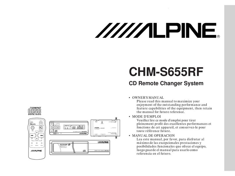
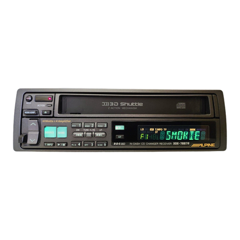
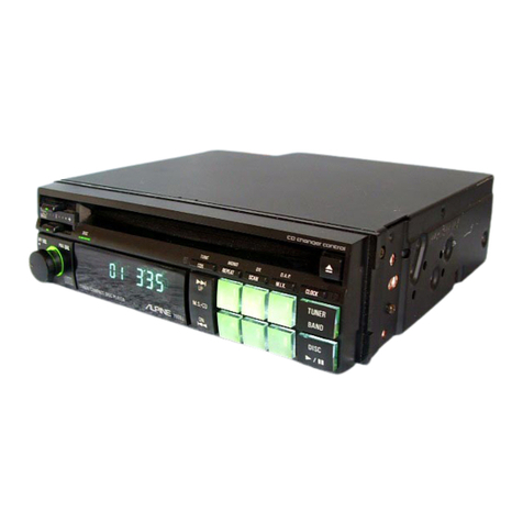
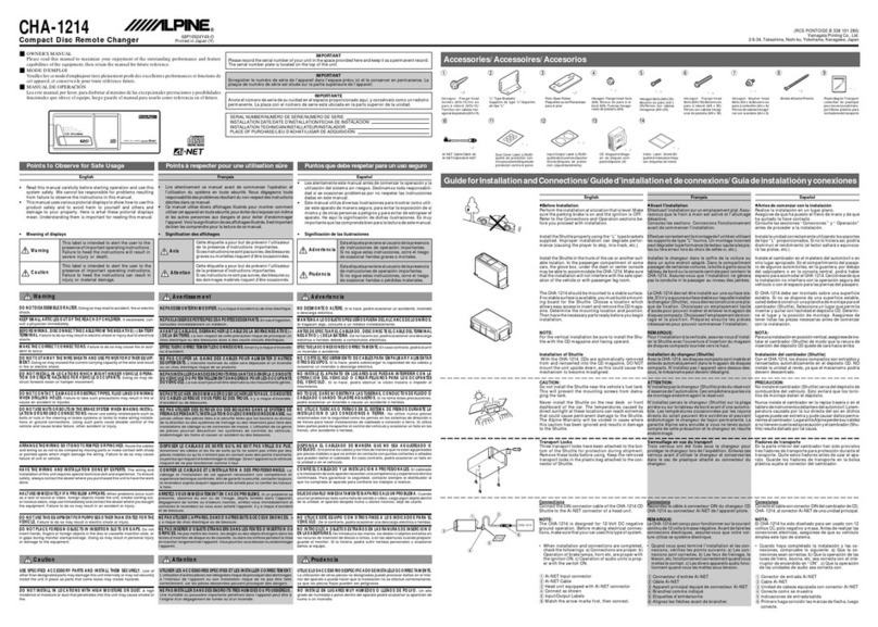
  9. Alpine DP-S Series User manual

Alpine DP-S Series User manual

SERVICE
MANUAL
ZILPIN
CD
Player
Mechanism
ADDENDUM
&
REVISED
(III)
Se
-SSERIES
DP-S
SERIES
Contents
Mechanism
Function
Description
-<<rrcc
cece
treet
ree
eee
ener
e
ee
eee
ener
e
cnr
tebe
enn
E
etn Een
tenes
3
Disassembly
Instructions
(For
DP24A010/DP24A020/DP24A110/DP24A11A/DP24A210
models)
crrrte
reece
eter
teeter
enes
11
CD
Mechanism
Assembly
Parts
List
(For
DP24A010,/DP24A020,/DP24A110/DP24A11A/DP24A210
models)
ccrrer
rete
ester
ee
eee
eee
15
Exploded
View
(CD
Mechanism)
(For
DP24A010,/DP24A020,/DP24A110,/DP24A11A,/DP24A210
models)
crest
sree
treet
tere
eee
e
eens
17
CD
Mechanism
Assembly
Parts
List
(For
DP24A220
model)
cerrer
rer
rr
eet
eet
e
eee
teen
nee
nee
e
eee
nes
19
Exploded
View
(CD
Mechanism)
(For
DP24A220
model)
crrttrtee
settee
reenter
ettenee
eect
nnn
n
ee
eeeet
anes
24
CD
Mechanism
Assembly
Parts
List
(For
DP22A070,/DP22A080
DP22A310/DP22A320
models)
-::--
23
Exploded
View
(CD
Mechanism)
(For
DP22A070/DP22A080
DP22A310,//DP22A320
models)
<«rrcreees
25
Disassembly
Instructions
(For
DP22A070
“DP22A080
DP22A310,/DP22A320
models)
vrrrtrttt
rere
eee
27
to
to
to
to
to
to
to
to
10
14
16
18
20
22
24
26
29
Mechanism
Function
Description
Function
LOADING
(of
a
12cm
CD)
Clamper
Description
The
beam
to
the
photo
sensor
(A)
will
be
broken
when
a
disc
is
in-
serted
into-the
loading
position.
The
mechanism
detects
the
disc
insertion
and
actuates
the
Loading
motor
to
rotate.
The
rotation
of
motor
is
transmitted
to
the
drive
(B)
and
(A).
roller
through
gears
(E),
(D),
The
disc
will
be
pinched
between
the
drive
roller
and
the
upper
guide
and
pulled
into
the
mechanism.
The
disc
reaches
to
the
sensor
gate
mechanism.
The
beam
to
the
is
broken,
and
simultaneously
the
micro-processor
discriminates
12
or
8cm
CD
size
depending
on
the
photo
sensor
(B).
is
broken,
the
micro-processor
detects
that
the
disc
is
a
12cm
CD
and
it
continues
feeding
the
disc.
photo
sensor
(D)
If
the
beam
to
the
photo
sensor
(B)
Sensor
Gate
Mechanism
Photo
Sensor
(D)
Solenoid
Arm
Solenoid
a
Photo
Se
B
nsor
(B)
ee
x
8cm
Disc
Eject
Position
en
ee
ur
alae
Photo
Sensor
(A)
12cm
Disc
Eject
Position
Figure
1
Drive
Roller
Gear
(A)
DP-S
SERIES
Illustration
Figure
Figure
Clamp
End
Switch
Cam
Photo
Sensor
(C)
Loading
Motor
Figure
2
Cam
Gear
Gear
(D)
Gear
(E)
DP-S
SERIES
Function
Step
Description
Ilustration
LOADING
The
disc
touches
the
left
and
right
stopper
pins,
and
push
them
by
(of
a
12cm
CD)
the
feed
mechanism.
By
pushing
the
stopper
pins,
the
left
and
right
lock
levers
rotate
and
the
lock
pins
remove
from
the
lock
position
of
the
guide
holes.
ok
The
disc
touches
the
disc
stopper
and
moves
the
unlocked
sensor
gate
. .
;
Figure
to
the
outer
direction
by
the
feed
mechanism.
If
the
disc
reaches
to
the
end
position,
the
beam
reaches
to
the
photo
sensor
(B).
The
mechanism
detects
that
the
disc
is
pulled
into
the
chucking
_
:
:
Figure
position
and
starts
chucking
action.
Disc
Stopper
Lever
(B)
Left
lock
Lever
Arm
Clamp
Guide
hole
Lever
(A)
Right
lock
Lever
;
Disc
Stopper
Reverse
Pin
Reverse
spring
Right
stopper
pin
Left
stopper
pin
Photo
Sensor
(B)
Photo
Sensor
(D)
Photo
Sensor
(B)
Left
lock
pin
Right
lock
pin
Figure
4
Figure
3
DP-S
SERIES
Function
Description
Illustration
LOADING
The
same
process
as
12cm
CD
loading
operation
steps@~@.
Figure
1
(of
a
8cm
CD)
Figure
2
Figure
7
The
disc
reaches
to
the
sensor
gate
mechanism.
The
sensor
gate
mechanism
moves
depending
on
the
disc
insertion
position
at
the
disc
slot
as
follows.
A)
When
the
disc
is
inserted
at
the
center
of
the
slot.
The
disc
touches
to
the
disc
stopper.
The
disc
cannot
push
both
the
left
and
right
stopper
pins,
so
that
the
locking
pins
cannot
be
released.
The
disc
movement
stops
there.
B)
When
the
disc
is
inserted
at
the
deviated
position
to
the
left
or
right
from
the
center
of
the
slot.
First,
the
disc
pushes
the
left
or
right
stopper
pin.
The
disc
cannot
push
the
another
stopper
pin,
so
that
the
locking
pins
cannot
be
released.
The
disc
moves
by
the
shape
of
the
disc
stopper
to
the
center
position
and
stops.
Figure
5
If
the
beam
reaches
to
the
photo
sensor
(B)
and
(C)
when
the
beam
to
the
photo
sensor
(D)
is
broken
by
the
disc,
the
mechanism
discriminates
that
the
8cm
CD
is
in
the
chucking
position,
and
starts
chucking
action.
Figure
5
Only
one
(left
or
right)
lock
pin
is
released
Photo
Sensor
(D)
Lever
(A)
Reverse
Pin
Figure
6
BhotS
Sensor
(B)
Photo
Sensor
(C)
When
a
disc
is
inserted
at
the
left
from
the
center
of
the
slot.
Figure
5
DP-S
SERIES
psa
wees
The
mechanism
detects
that
the
disc
is
pulled
into
the
Chucking
position
and
pulls
the
solenoid.
CHUCKING
The
solenoid
arm
connected
with
the
solenoid
starts
to
rotate
and
transmits
the
rotation
to
the
cam
gear.
The
cam
gear
starts
to
rotate
and
engages
with
the
gear
(C)
then
the
driving
power
of
the
Loading
motor
will
be
transmitted
to
the
cam
gear.
The
rotating
cam
gear
engages
with
rack,
and
moves
the
rack
toward
the
right.
Pete
With
the
movement
of
the
rack,
the
following
functions
will
be
performed
simultaneously.
.
The
clamper
moves
downward
and
chucks
the
disc.
Figure
8
The
drive
roller
moves
downward
and
releases
the
disc
pinched
Figure
9
previously
and
moves
the
disc
downward.
Figure
10
Releases
the
locking
on
the
pickup
block
and
places
the
unit
in
the
floating
status.
The
rack
slides
to
the
right
end and
releases
the
engagements
between
the
gear
(C)
and
the
cam
gear
as
well
as
the
cam
gear
and
rack,
and}
Figure
8
turns
the
clamp
end
switch
on.
The
mechanism
detects
that
the
clamp
operation
has
finished,
and
the
Loading
motor
stops
rotating.
Figure
8
Clamper
Upper
Guide
us
Solenoid
Drive
roller
Clamp
End
Switch
\
Cam
Gear
Gear
(C}
Rack
Loading
Motor
Gear
(A)
Figure
7
Lowered
clamp
position
Solenoid
Drive
Roller
Gear
(C)
Loading
Motor
Cam
Gear
Gear
(A)
Solenoid
Arm
Solenoid
Solenoid
Engaging
Cam
Gear
Gear
(C)
/
Solenoid
Arm
Q
Clamp
End
Switch
Engaging
Cam
Gear
Figure
8
Damper
Move
with
rack
simultaneously
Floating
Position
Spindle
Motor
Loading
Cam
Rivet
Assembly
Trigger
Lever
Servo
Motor
Reverse
Pin
Cam
shaft:
United
with
Loading
cam
moves
Trigger
Lever.
Figure
9
DP-S
SERIES
DP-S
SERIES
PLAY
The
spindle
motor
rotates
the
disc.
Figure
10
The
rotation
of
the
servo
motor
is
transmitted
to
the
shaft
screw
:
;
Figure
10
through
the
gear,
moves
the
pickup.
;
Figure
10
The
Inner
limit
switch
detects
the
lead-in
position
of
the
disc,
and
the
mechanism
begins
to
read
the
information
of
the
disc.
Shaft
screw
Floating
status
Servo
Motor
Inner
limit
switch
Spindle
Motor
Figure
10
EJECTION
(of
a
12cm
CD)
The
solenoid
arm
engaged
with
the
solenoid
starts
rotating
and
the
cam
gear
engages
with
the
gear
(C).
The
cam
gear
rotates
and
engages
with
the
rack
and
then
moves
the
rack
in
the
left
direction.
Engaging
with
the
movement
of
the
rack,
the
following
functions
will
be
performed
simultaneously.
The
clamper
moves
upward
and
releases
the
disc.
The
driving
roller
moves
up
and
lifts
the
disc,
and
pinches
the
disc
between
it
and
the
upper
guide.
Locks
the
pickup
block.
The
reverse
pin
moves
with
engaging
the
levers
(A)
and
(B),
which
moves
the
sensor
gate
mechanism
to
the
original
position.
When
the
rack
moves
to
the
left,
the
engagements
between
the
gear
(C)
and
the
cam
gear,
the
cam
gear
and
the
rack
will
be
released.
DP-S
SERIES
Function
Description
EJECTION
Cof
a
12cm
CD)
The
disc
which
is
pinched
between
the
drive
roller
and
the
upper
guide
moves
to
the
outside
of
the
mechanism.
When
the
disc
is
sent
out
to
the
EJECT
position,
the
beam
broken
by
the
disc
is
released
and
reaches
the
photo
sensor
(B).
The
mechanism
detects
that
the
disc
has
come
out
to
the
EJECT
position
and
stops
the
motor
rotation.
The
mechanism
detects
that
all
functions
have
finished
when
the
disc
is
pulled
out
from
the
mechanism
and
beam
is
passed
through
to
the
photo
sensor
(A).
RELOAD
lf
the
disc
is
not
pulled
out
from
the
mechanism
for
15
seconds
after
it
comes
to
(of
a
12cm
CD)
the
EJECT
position,
the
mechanism
actuates
the
Loading
function
steps
©
—
©.
EJECTION
(of
a
Bom
CD)
The
same
process
as
12cm
CD
Eject
operation
steps
O~@.
Engaging
with
the
movement
of
the
rack,
the
following
functions
will
be
performed
simultaneously.
A.
B.
ir
The
same
process
as
12cm
CD
Eject
operation
step@
—A,
B,
C.
C.
The
same
process
as
12cm
CD
Eject
operation
step
©.
The
disc
which
is
pinched
between
the
drive
roller
and
the
upper
guide
moves
to
the
outside
of
the
mechanism.
The
disc
is
released
from
the
drive
roller
and
stops.
If
the
beam
reaches
the
photo
sensor
(C)
after
1.5
seconds
from
starting
ejection,
the
motor
stops.
The
mechanism
detects
that
all
functions
have
finished,
when
the
disc
is
pulled
out
from
the
mechanism
and
beam
is
passed
through
to
the
photo
sensor
(A).
DP-S
SERIES
|
Function
TROUBLE
SHOOTING
(While
Loading
a
12cm
CD)
Description
_————
ee
—————
es
If
the
beam
to
the
photo
sensor
(D)
is
not
broken
within
3
seconds
after
the
Loading
motor
begins
rotating
as
described
in
the
Loading
operation
step
©,
the
mechanism
takes
it
as
trouble
and
rotates
the
Loading
motor
inversely
and
pushes
the
disc
out
to
the
EJECT
position.
(While
loading
a
8cm
CD)
(While
Chucking)
(While
Playing)
(While
Ejecting
a
12cm
CD)
(While
Ejecting
a
8cm
CD)
In
the
Loading
step
@,
if
the
beam
does
not
reach
the
photo
sensor
(D)
within
3
seconds
after
the
beam
to
the
photo
sensor
(B)
is
broken,
the
mechanism
take
it
as
trouble
and
rotates
the
loading
motor
inversely
and
push
the
disc
out
to
the
eject
position.
If
the
disc
is
removed
and
the
beam
reaches
the
photo
sensor
(A),
the
mechanism
performs
loading,
chucking
and
ejection
without
a
disc.
(To
place
the
sensor
gate
mechanism
from
the
END
position
to
the
original
position
the
mechanism
operates
the
Ejection
step
©
—d)
When
the
disc
is
pulled
out
during
the
loading
process,
the
Loading
motor
rotates
inversely
and
stops
the
rotating
after
certain
seconds.
The
same
process
as
12cm
CD
loading
operation
step®.
The
same
process
as
12cm
CD
loading
operation
step@).
In
the
chucking
operation
(step
@)
if
the
Clamp
End
Switch
doesn't
turn
on
within
3
seconds
after
the
solenoid
is
pulled,
the
mechanism
takes
it
as
trouble
and
rotates
the
Loading
motor
inversely
and
pushes
the
disc
out
and
stops
at
the
EJECT
position.
When
the
disc
doesn't
come
to
the
EJECT
position,
the
motor
stops
the
rotating
after
certain
seconds.
After
disc
chucking,
if
the
mechanism
is
unable
to
read
the
information
of
the
disc
for
some
reason,
it
actuates
the
EJECTION
operation
steps.
If
the
disc
doesn’t
come
to
the
EJECT
position
within
5
seconds
after
the
solenoid
is
pulled
in
the
EJECTION
operation
step
@,
the
mechanism
takes
it
as
trouble
and
rotates
the
Loading
motor
inversely
and
performs
the
Loading
operation
steps.
If
the
beam
does
not
reach
the
photo
sensor
(C)
within
1.5
seconds
after
starting
ejection,
the
motor
continues
rotating.
If
the
beam
does
not
reach
the
photo
sensor
(C)
within
5
seconds
after
starting
ejection,
the
mechanism
takes
it
as
trouble
and
changes
the
motor
rotating
direction
and
performs
loading
steps.
40
DP-S
SERIES
Disassembly
Instructions
@
For
DP24A010,/DP24A020//
Sesiy
eens
Loading
Motor
DP24A110./DP24A11A/“
P.C.
Board
goider
()
DP24A210/’
DP24A220
0
models
1.
Removal
of
the
Load/Photo
P.
C.
Boards
(1)
Remove
three
screws
marked
with
“O”
as
shown
in
Figures
11
and
12.
(2)
Remove
the
solder
(c)
as
shown
in
Figure
11.
2.
Removal
of
the
LED
P.
C.
Board
(1)
Remove
the
solder
(b)
as
shown
in
Figure
12.
(2)
Remove
the
screw
marked
with
“A”
as
shown
in
Figure
12.
3.
Removal
of
the
End
Switch
(A)
P.
C.
Board
(1)
Remove
the
two
screws
marked
with
“@”
as
shown
in
Figure
13.
(2)
Remove
the
two
lead
wires
from
the
solenoid.
Spindle
Motor
Head
Unit
Pick-Up
Servo
Motor
Unit
;
4.
Removal
of
the
Pick-Up
Unit
Figure
11
(1)
Remove
the
cam
gear
and
the
gear
(C)
as
shown
Rivet
Chassis
Load/Photo
(2)
in
Figure
13.
P.
C.
Board
©
—
Solder
(a)
(2)
Remove
the
four
screws
marked
with
“xX”
as
shown
Figures
13
and
14.
(3)
Both
the
Pick-Up
Unit
and
Rivet
Loading
Bracket
Assembly
will
be
removed.
Note:The
cam
gear
and
gear
(C)
are
mounted
with
washers.
Do
not
lose
the
washers,
keep
them
carefully.
Tightening
Torque
Washer
(C)
Solenoid
Gear
LED
P.
C.
Board
Solder
(b)
Figure
12
End
Switch
(A)
ony
WHS
P.
C.
Board
amend
Cam
Gear
@
Tightening
Torque
Tightening
Torque
tka
om
Figure
13
scious
Tightening
Torque
Figure
14
-1i-
DP-S
SERIES
5.
Removal
of
the
Rivet
Loading
Bracket
Assembly
(1)
After
removing
the
Pick-Up
Unit,
pull
the
Rivet
Loading
Bracket
Assembly
toward
you
while
twisting
it
in
the
direction
shown
by
the
arrow,
as
shown
in
Figure
15.
6.
Removal
of
the
Servo
Motor
[For
DP24A010
/
DP24A020
DP24A110
/
DP24A11A
/
DP24A210
models
only]
(1)
After
removing
the
Rivet
Loading
Bracket
Assembly,
remove
the
two
screws
marked
with
“(]”
as
shown
in
Figure
16.
Note
:Both
the
Servo
Motor
and
Flexible
wire
will
be
removed.
Do
not
damage
the
flexible
wire.
7.
Removal
of
the
Head
Unit
[For
DP24A010/
DP24A020
/DP24A110,/DP24A11A/DP24A210
models
only]
Head
Unit
Loading
Motor
(1)
After
removing
the
Servo
Motor,
remove
the
two
Rivet
Loading
‘ :
:
re
7 i
Rivet
Loading
Cam
screws
marked
with
“@”
as
shown
in
Figure
16.
Bracket
Assembly
Assembly
Figure
15
Head
Unit
Flexible
P.
C.
Board
Pick-Up
Unit
:
Spindle
Motor
Servo
; :
Motor
Tightening
Torque
Tightening
Torque
2~2.5kg
cm
2~2.5kg
>
cm
Tightening
Torque
Figure
16
-12-
6.
Removal
of
the
Servo
Motor
(For
DP24A220
models
only]
(1)
After
removing
the
Rivet
Loading
Bracket
Assembly,
remove
the
two
screws
marked
with
“C1”
as
shown
in
Figure
17.
Note
:Both
the
Servo
Motor
and
Flexible
wire
will
be
removed.
Do
not
damage
the
flexible
wire.
7.
Removal
of
the
Head
Unit
[For
DP24A220
models
only]
(1)
After
removing
the
Servo
Motor,
remove
the
five
screws
marked
with
“@”
as
shown
in
Figure
17.
oa
DP-S
SERIES
Tightening
Torque
Tightening
Pick—Up
Unit
ras
=
~
a
Spindle
Motor
Head
Unit
Tightening
Torque
8.
Removal
of
the
Rivet
Loading
Cam
Assembly
(1)
After
removing
the
Rivet
Loading
Bracket
Assembly,
remove
the
gear
(D)
and
gear
(E)
as
shown
in
Figure
18.
(2)
Remove
the
Washer
and
“E”
ring
as
shown
in
Figures
18
and
20.
Note:
1)
Do
not
lose
the
washer
and
“E”
ring
and
keep
them
carefully.
2)
Remove
the
spring
and
them
at
the
same
time
as
shown
in
Figure
18.
Clearance
Gap
1.55+0.05mm
Spindle
Table
Spindle
Motor
Figure
19
Tightening
Torque
1.5~2kg
+
cm
Gear
(D)
Loading
Motor
43>
r
Servo
Motor
Tightening
Torque
Spring
Torque
Flexible
¢
[1.3k9
+
om]
P.C.
Board
C]
Tightening
Torque
Figure
17
Rivet
Loading
Cam
Assembly
Figure
18
Rivet
Loading
Bracket
Assembly
DP-S
SERIES
9.
Removal
of
the
Loading
Motor.
(1)
After
removing
the
Rivet
Loading
Cam
Assembly,
Rivet
Loading
remove
the
two
screws
marked
with
“A”
as
Bracket
Assembly
shown
in
Figure
20.
see
Useful
hints
for
remounting
the
cam
gear
and
gear
(C).
(1)
Set
the
Rivet
Loading
cam
Assembly
to
the
loading
position
as
shown
in
Figure
21.
on
(2)
Engage
the
cam
gear
with
the
gear
(C)
as
shown
in
the
Figure
22,
and
mount
them
on
the
shafts
(A)
of
the
Arm
Load
(R)
Assembly
as
shown
in
Figure
21.
Rivet
Loading
Cam
A
“E”
ring
Assembly
Figure
20
Arm
Load
(R)
Assembly
Shaft
Gear
(C)
(A)
Solenoid
Cam_
Gear
}
Rivet
Loading
End
Switch
(A)
Figure
22
Cam
Assembly
P.
C.
Board
(Loading
Position)
Caution
on
remounting
the
Servo
Motor.
Figure
21
(1)
After
mounting
the
servo
motor,
make
sure
the
clearance
between
the
servo
motor
and
flexible
wire
is
more
than
0.5mm
as
shown
in
Figure
23.
Flexible
Wire
a
“+
iAH
(more
than
0.5mm)
Servo’
Motor
Figure
23
~14-
CD
Mechanism
Assembly
Parts
List
@
For
DP24A010,/DP24A020
/DP24A110/DP24A11A,/DP24A210
Models
203
204
205
206
208
209
210
211
213
214
215
216
218
219
221
226
227
228
229
231
232
233
234
237
238
239
240
NOTE
:
15013518W01
5-C
(03844205614
5-B
|30T73687F18
4-C
|41B12249W02
04B41345P06
41A20219W01
5-F
|45A90817F01
5-F
|45A90818F01
5-F
|41A92364F01
2-F
|07B10907W01
47A61544F02
3-G
|75A20934W01
4-F
184A92276F01
03D40014G66
03D40014G07
44B90838F01
4C
|46A91007F02
4-E
|41B12249W07
2-F
|49B90822F01
43A90873F01
41A90877F01
03D40014G662
5-C
|44A90836F
01
5-C
|44A90837F01
5-C
/04B41345P01
75B11922W02
15A12929W01
4-D
|04C42091G06
5-C
|04C42091G11
3-C
|03S894385F01
41A11905W01
4-F
104042091G05
2-B
JO7A10921W01
4A
|03A90175F05
03894385F09
The
parts
without
x
i
Guide,
Top
(DP-2)
Screw,
Pan
(M2
x
5)
Parailel
Wire
(2P)
Spring,
Pull
Washer,
Lock
(M2.1)
Spring,
ROL
(L)
Arm,
Solenoid
(1)
Arm,
Solenoid
(2)
Spring,
Solenoid
Stopper,
Disc
Plunger,
RF
Solenoid
Cushion,
Magnet
(B)
END
Switch
(A)
P.C.
Board
Screw,
W/Washer
(M2
x
3,5)
Screw,
W/Washer
(M2
x
4)
Gear,
Cam
Stud,
Gear
Spring,
Pull
Roller
(G)
Bush,
Roller
Spring,
Cam
Screw,
W/Washer
(M2
x
3)
Gear
(D)
Gear
(E)
Washer,
Lock
(M1.2)
Damper,
DP-3
Holder,
Damper—3
Ring
“E”
(M
1.5)
Ring
“E”
(M2.5)
Screw,
Pan
(M1.7
xX
2.3)
Spring,
Trigger
Ring
“E”
(M2)
Bracket,
Shaft
Screw,
Bind
(M2
x
3.7)
Screw,
Pan
(M2
x
3)
part
numbers
are
not
supplied.
03D40014G75
3-B
|
03D40121T38
3-E
|43A22104W01
3-B
|07B10923W01
2-C
|47A20146W01
43A11901W01
04B41345P15
3-D
|01812125Wwo1
3-B
|47A10927W01
44A90998F01
44A90996F01
4-G
|
41B12249W08
4-C
|44A90997F01
04B41345P02
4F
|03894385F
23
03S94385F07
3-C
|07C10922W01
4-B
141A10928W03
5-G
|
04840075612
3-B
|41010925W01
14A96087F01
4-B
|84T15149W01
4-E
|01A12222W01
4-E
|01B12123W01
3-F
|41A11903W01
04B41345P04
3-E
|07A30152W01
3-F
|
41B12249W01
4-F
|07A11468W01
44A90830F01
03$44205G694
47A21175W01
41B12249W03
41B12249W04
41B12249W05
eee
Screw,
W//Washer
(M2
x
Q)
Screw,
W/Double
Washer
(M2
x
5)
Table,
Spindle
Bracket,
Screw
Shaft,
Pick-up
Bush,
Triger
(A)
Washer,
Lock
(M1.2)
Assy.,
Riv.
Pick
Chassis
Shaft,
Screw
Gear,
Screw
Gear,
Motor
Spring,
Pull
Gear,
Middle
Washer,
Lock
(M1.7)
Screw,
Pan
(M2
x
5)
Screw,
Pan
(M2
x
2)
Bracket,
Motor
Spring,
Shaft
Washer,
Polyslider
(M3.1)
Spring,
Nut
Sheet.
Table
FPC
Actuate
P.C.Board
Assy.,
Clamper
Rivet
Assy.,
Riv.
Arm
Clamp
Spring,
Lever
Washer,
Lock
(M2.6)
Bracket,
Disc
Stopper
Spring,
Pull
Plate,
Top
Rack,
Cam
Screw,
Pan
(M1.7
x
2)
Shaft,
Pick-up
Spring,
Pull
Spring,
Pull
Spring,
Pull
DP-S
SERIES
DP-S
SERIES
284
287
288
289
290
291
292
293
294
295
296
297
or
298
299
300
301
302
303
304
305
NOTE
4E
5-F
4F
3-C
BF
3-F
3C
aE
4-G
4G
3-C
4E
4D
3-C
3-B
43A20208W01
307
73687F19
01A92321F02
01T15181W01
75A21138W01
03A90175F01
03A90175F02
41B90875F07
44A90834F01
44A90835F01
43A13508W01
41A96086F01
43A41006F01
43A22457W01
43A22457W02
7T5A20928W01
04B41345P24
43A20208W02
03S94385F
14
03S894385F25
75A20128W01
03844205696
03844205695
03894385F
24
88T15309W01
48T16057W02
01V13100W97
59T91005F01
59T52973F03
487T92913F01
40T71025F03
40T71025F01
01A90816F01
Spacer,
LED
Parallel
Wire
(2P)
Assy.,
Bracket
Rivet
(CLP—LP)
Assy.,
Clutch
DP
Sheet,
Shaft
Screw,
Bind
(M2
x
4)
Screw,
Bind
(M2
xX
3)
Spring,
Pull
Gear
(B)
Gear
(C)
Spacer,
Shaft
Spring,
Arm
Clamp
Spacer,
Polyslider
Spacer
Spacer
Rubber,
Top
Chassis
Washer,
Lock
(M2.1)
Spacer,
LED
(A)
Screw,
Countersink
(M2.6
X
3)
Screw,
Pan
(M2
x
4)
Sheet,
Holder
Screw,
Bind
(M2
x
5)
Screw,
Bind
(M2
x
3)
Screw,
Pan
(M2
x
3)
Miscellaneous
Pick-up,
Unit
LED,
AN501
(RED)
Assy.,
Motor
Load
Motor,
Spindle
Motor,
Servo
Transistor,
Photo
PT360
Switch,
Detector
(CAM
END)
Switch,
Detector
(LIMIT)
Assy.,
Solenoid
DP
Frame
:
The
parts
without
part
numbers
are
not
supplied.
x
el
Part
No.
Description
a
=46=
Exploded
View
(CD
Mechanism)
@
For
DP24A010
/
DP24A020
/
DP24A110
/
DP24A11A
/
DP24A210
Models
Tightening
Torque
2.5
kg*cm
2.5kg-cm
Tightening
Torque
2kg-cm
Tightening
Torque
TighteningTorque
GREASE
EM-60L
@®
|
MOLYKOTE
£
PASTE
®
©
|
GREASE
PG-67!
Tightening
Torque
2.5
kg-cm
Tightening
—/
"6
ng
Torque
DP-S
SERIES
DP-S
SERIES
CD
Mechanism
Assembly
Parts
List
7
Bearing
:
Batis:
@For
DP24A220
Model
41B12249W05
|
Spring,
Pull
ce
43A20208W01
|
Spacer,
LED
30T73687F19
|
Parallel
Wire
(2P)
01A92321F02
|
Assy.,
Bracket
Rivet
(CLP—LP)
Part
No.
Description
15C13518W01
|
Guide,
Top
Part
No.
Description
03S94385F20
|
Screw,
Pan
(DP
~
2)
(M2
x
8.5)
01715181W01
|
Assy.,
Clutch
DP
203
|
5-C
|03S844205G614
|
Screw,
Pan
03D40121T38
|
Screw,
(M2
x
5)
W//Double
Washer
07A30961W01j
Stopper,
Shaft
(B)
204
|
5-B
|30T73687F18
|
Parallel
Wire
(2P)
205
|
4-C
}41B12249W02
|
Spring,
Pull
206
04B41345P06
|
Washer,
Lock
(M2.1)
(M2
x
5)
243
|
3-E
|43A30923W01|
Table,
Spindle
244
|
3-B
|07B10923W01!
Bracket,
Screw
245
47A30925W01!
Shaft,
Pick-up
03A90175F01
|
Screw,
Bind
(M2
x
4)
03A90175F02
|
Screw,
Bind
(M2
x
3)
41B90875F07
|
Spring,
Pull
44A90834F01
|
Gear
(B)
41A20219W01
|
Spring,
ROL
(L)
43A11901W01}
Bush,
Triger
(A)
208
|
5-F
]45A90817F01
|
Arm,
Solenoid
(1)
247
04B41345P15
|
Washer,
Lock
209
|
5-F
|45A90818F01
|
Arm,
Solenoid
(2)
(M1.2)
44A90835F01
|
Gear
(C)
210
|
5-F
|41A92364F01
|
Spring,
Solenoid
248
|
3-D]01B12125W01|
Assy.,
Riv.
03870494F14
|
Screw,
Pan
211
|
2-F
|07B10907W01
|
Stopper,
Disc Pick
Chassis
(M1.7
x
4)
04840075G06
|
Washer,
Plyslider
(M2.1)
249
|
3-B
/47A10927W02|
Shaft,
Screw
250
|
3-B
|44A90998F01
|
Gear,
Screw
47A61544F02
|
Plunger,
RF
Solenoid
43A41006F01
|
Spacer,
Polyslider
213
|
3-G
175A20934W01
|
Cushion,
Magnet
44A90996F01
|
Gear,
Motor
03S94385F24
|
Screw,
Pan
(B)
253)
4-G
|41B12249W08]
Spring,
Pull
(M2
x
3)
214
|
3-F
|84A92276F01
|
END
Switch
(A)
254]
4-C
|}44A90997F01
|
Gear,
Middle
P.C.
Board
255
04B41345P02
|
Washer,
Lock
75A20928W01
|
Rubber,
215
03D40014G66
|
Screw,
W/“
Washer
(M1.7)
Top
Chassis
(M2
x
3.5)
256
|
4-F
|03S94385F23
|
Screw,
Pan
04B41345P24
|
Washer,
216
03D40014G07
|
Screw,
W/Washer
(M2
x
5)
Lock
(M2.1)
(M2
x
4)
43A20208W02
|
Spacer,
LED
(A)
03S894385F14
|
Screw,
Countersink
(M2.6
x
3)
03S894385F25
|
Screw,
Pan
(M2
x
4)
03S94385F07
|
Screw,
Pan
(M2
x
2)
258
|
3-C
|07C10922W01]
Bracket,
Motor
259
|
4B
|141A10928W03}
Spring,
Shaft
261
03D40014G02
|
Screw,
W/Washer
(M2
x
6)
262]
3-E
|41A10928W04}
Spring,
Comp
44B90838F01
|
Gear,
Cam
218
|
4C
|46A91007F02
|
Stud,
Gear
219
|
4-£
|41B12249W07
|
Spring,
Pull
221
|
2-F
|49B90822F01
|
Roller
(G)
43A90873F01
|
Bush,
Roller
75A20128W01
|
Sheet,
Holder
41A90877F01
|
Spring,
Cam
226
03D40014G62
|
Screw,
W/Washer
(M2
x
3)
227
|
5-C
|44A90836F01
|
Gear
(D)
03844205696
|
Screw,
Bind
(M2
x
5)
03844205695
|
Screw,
Bind
(M2
x
4)
41010825W02]
Spring,
Nut
264]
3-E
|14A96087F01
|
Sheet,
Table
265}
4-B/84T15149W01]
FPC
Actuate
228
|
5-C
144A90837F01
|
Gear
(E)
P.C.Board
229
|
5-C
|04B41345P01
|
Washer,
Lock
266
|
4E
|01A31429W01}
Assy.,
Clamper
(M1.2)
Rivet
267}
3-E
}01B12123W01]
Assy.,
Riv.
75B11922W02
;
Damper,
DP—3
231
15A12929W01
|
Holder,
Damper—3
Arm
Clamp
Miscellaneous
232
04C042091G06
|
Ring
“E”
41A11903W01}
Spring,
Lever
88T15309W01
}
Pick-up,
Unit
(M1.5)
270}
3-F
|04B41345P04
|
Washer,
Lock
48T16057W02
|
LED,
AN501
(RED)
233
|
5-C
]04C42091G11
|
Ring
“E”
(M2.6)
01V13100W9Q7
|
Assy.,
Motor
Load
(M2.5)
271
3-E
07A30152W01
Bracket,
Disc
59T91005F02
Motor,
Spindle
234
|
3-C
(27C30861W01
|
Base,
Pick-up
Stopper
59T52973F03
|
Motor,
Servo
272
|
3-F
|}41B12249W01]
Spring,
Pull
41A11905W01
|
Spring,
Trigger
273}
4-F
|07A11468W01}
Plate,
Top
48T92913F01
|
Transistor,
Photo
237
|
4-F
|04C42091G05
|
Ring
“E”
PT360
ve?
44A90830F01
|
Rack,
Cam
40T71025F03
|
Switch,
Detector
238
|
3-D
{03S94385F26
|
Screw
Countersink
275
|
4-F
|03S44205G94
|
Screw,
Pan
(CAM
END)
(M1.7x2.6)
(M17
x
2)
40T71025F01
|
Switch,
Detector
239
|
4A
|03A90175F05
|
Screw,
Bind
277
|
3-E
|43B30924W01}
Spindle,
Hub
(LIMIT)
(M2
x
3.7)
279
1-¢
41B12249W03
Spring,
Pull
01A90816F01
Assy.,
Solenoid
240
03894385F09
|
Screw,
Pan
280]
2E
|41B12249W04]
Spring,
Pull
DP
Frame
(M2
x
3)
NOTE:
The
parts
without
part
numbers
are
not
supplied.
NOTE:
The
parts
without
part
numbers
are
not
supplied,
19
-20-
Exploded
View
(CD
Mechanism)
@
For
DP24A220
Model
Tightening
Torq
|
2.5
kg*cm
g
g
oO
rom
Fe
L
3
oa
pe
£
oa
E
i=
oO
2
‘S.
5
22
ae
<2
a=
z
be
DN
i=
as
ap
;
YR
->As
,
|
Tightening
Torque
Tightening
Torque
2to2.5kg-cm
Tightening
Torque
2.5
kg-cm
Tightening
Torque
2.5kg-cm
TighteningTorque
ao]
4
F
a)
o
a
a
—
re
wl)
at)
ort
9
Nirver
ier
Y
/
wy)
“ls
]o
Ab
sayaal
lie
®
EA!
g
2
y
gs
$
Oo
}]uw
|
w
3
‘é
Qe
ea
ea
ea
iow
Ss
Ss
¥
Q
2)
g
q
S
=
e
p
or
/
2 2
2
i
eé
Eldiwiwu
’
\
2
ba
Z2§
AN
25
Bs
ee5
[=
2s
a}>=/o
oO
€¢
;
re
etd.
aay
ee
aed
:
So
/
oo
Lo
oD
es
Lo
‘
=
2
ez!
Ee
Ex
a
ees
aN
20
©
2a
2a
||
ea
S-
||
Sa
‘|
@|@|
©
2
a
t=
E -
=
Gg
e
GS
DH
&
7
S
&
/
Cm
A
|
Be
|
C
|
oD
|
E
|
F-x
|
G
l
H
DP-S
SERIES
DP-S
SERIES
CD
Mechanism
Assembly
Parts
List
@
For
DP22A070,/DP22A080
/DP22A310,/DP22A320
Models
Part
No.
Description
Description
Description
03844205614
307
73687F18
03A90175F01
04B41345P06
41A20219W01
45A90817F01
45A90818F01
41A92364F01
07B10907W02
07B10907W02
07B10907W02
47A61544F02
03894385F
14
84A92276F01
03D40014G66
030D40014G07
44B90838F01
46A91007F01
41B12249W07
49B90822F01
43A90873F01
41A90877F01
03D40014G62
44A90836F01
44A90837F01
04B41345P01
75B11922W02
15A12929W01
04042091G06
Guide,
Top
(DP
—
2)
Screw,
Pan
(M2x5)
Parallel,
Wire
(2P)
Screw,
Bind
(M2
x4)
Washer,
Lock
(M2.1)
Spring,
ROL
Arm,
Solenoid.
(1)
Arm,
Solenoid.
(2)
Spring,
Solenoid.
Stopper,
Disc
Stopper,
Disc
Stopper,
Disc
Plunger,
F/R
Screw,
Countersink
(M2.6
x
3)
END
Switch
(A)
P.C.
Board
Screw,
W/Washer
(M2
x
3.5)
Screw,
W
/Washer
(M2
x
4)
Gear,
Cam
Stud,
Gear
Spring,
Pull
Roller
(G)
Bush,
Roller
Spring,
Cam
Screw,
W//Washer
(M2
x
3)
Gear
(D)
Gear
(E)
Washer
Lock
(M1.2)
Damper,
DP-3
Holder,
Damper
DP-3
Ring
“E”
(M1.5)
Part
No.
04042091611
03S94385F01
41A11905W01
04B41345P04
04B41345P24
03894385F09
04B41345P15
30T73687F
14
43A22104W01
07A90992F01
47A91004F01
43A11901W01
03894385F
10
07A92196F01
03A91001F01
44A90998F01
44A90996F01
41B12249W08
44A90997F01
04B41345P13
03S894385F
23
03844205642
03844205642
03844205642
01V91700F07
41A90999F01
41B21241W02
30T92773F01
26A94948F01
26A94948F01
26A94948F01
26A94948F01
Description
Ring
“E”
(M2.5)
Screw,
Pan
(M1.7*
2.3)
Spring,
Trigger
Washer,
Lock
(M2.6)
Washer,
Lock
(M2.1)
Screw,
Pan
(M2
x3)
Washer,
Lock
(M1.2)
Parallel,
Wire
(3P)
Table,
Spindle
Bracket,
Screw
Shaft,
Pick-up
Bush,
Trigger
(A)
Screw,
Pan
(M2
x
4)
Bracket,
Fiex
Wire
Shaft,
Screw
Gear,
Screw
Gear,
Motor
Spring,
Pull
Gear,
Middle
Washer,
Lock
(M1.7)
Screw,
Pan
(M2x5)
Screw,
Pan
(M2.6
x
4)
Screw,
Pan
(M2.6
x
4)
Screw,
Pan
(M2.6
x
4)
Assy.,
Motor
Unit
Spring,
Screw
Spring,
Pull
Cable,
Flex
(16P)
Shield
Shield
Shield
Shield
14A96087F01
84T15747W01
01A12222W01
01B12123W01
41812249W01
43A90995F01
07A30152W01
41A11903W01
07A11468W01
44A90830F01
03844205694
01V23100W27
01V24900W02
01V24900W02
01V24900W02
41821241W01
41B21241W03
41B21241W04
43A20208W01
30T
73687F20
01A92321F02
01T15181W01
04B41345P02
03A90175F02
41B90875F07
44A90834F01
44A90835F01
43A20208W03
75A20128W01
03S894385F
10
03S894385F
12
43A41006F05
07A90993F01
01A90994F01
Sheet,
Table
FPC
Actuator
P.
C.
Board
Assy.,
Clamper
Rivet
Assy.,
Riv.
Arm
Clamp
Spring,
Slider
Stopper,
Shaft
Bracket,
Disc
Stopper
Spring,
Lever
Plate,
Top
Rack,
Cam
Screw,
CounterSink
(M2.6
x
8)
Assy.,
Pick-up
Unit-S2
Assy.,
Pick-up
Unit-S2
Assy.,
Pick-up
Unit-S2
Assy.,
Pick-up
Unit-S2
Spring,
Pull
Spring,
Pull
Spring,
Pull
Spacer,
LED
Parallel,
Wire
(2P)
Assy.,
Bracket,
Rivet
(CLP-LP)
Assy.,
DP
Clutch
Washer,
Lock
(M1.7)
Screw,
Bind
(M2
x
3)
Spring,
Pull
Gear
(B)
Gear
(C)
Spacer,
LED
(A)
Sheet,
Holder
Screw,
Pan
(M2
x
4)
Screw,
Pan
(M2.6
x
6)
Spacer,
Polyslider
Bracket,
Pick-up
Spring,
Nut
03S$94385F03
84T90887F01
14871058F40
03894385F06
41A94452F01
14A28008W01
41A96086F01
43A41006F01
03894385F
24
03844205696
03844205695
Screw,
Pan
(M1.7x
1.8)
FPC
PHOTO
P.
C.
Board
Insulator,
Cover
Screw,
Pan
(M2x
1.8)
Spring,
Motor
Spacer
Spring,
Arm
Clamp
Spacer,
Polyslider
Screw,
Pan
(M2
x
3)
Screw,
Bind
(M2
x
5)
Screw,
Bind
(M2
x
4)
Miscellaneous
88T90878F01
48T16057W02
01V21900W45
59T90879F01
59T91005F01
48T92913F01
40T71025F03
40T71025F01
01A90816F01
———
Pick-up,
Unit
LED,
AN501-B1
CRED)
Assy.,
Motor
Load
Motor,
Servo
Motor,
Spindle
Transistor,
Photo
PT360
Switch,
Detector
Switch,
Detector
Assy.,
Solenoid
DP
Frame
:
i i
Notes
:
The
parts
without
part
numbers
are
not
supplied.
Notes
:
The
parts
without
part
numbers
are
not
supplied.
A.
1
For
DP22A070
model
only,
(J
:
For
DP22A08O
model
only,
+
:
For
0P22A310
model
only,
4:
For
DP22A070
model
only,
()
:
For
DP22A080
model
only,
w
:
For
DP22A310
model
only,
©
+
For
DP22A320
modelonly,
Others
:
Common
©
:
For
DP22A320
model
only,
Others
:
Common
~23-
—~24~

This manual suits for next models

5

Other Alpine CD Player manuals

Alpine 7906R User manual

Alpine

Alpine 7906R User manual

Alpine 3DE-7887R User manual

Alpine

Alpine 3DE-7887R User manual

Alpine IVA-D100 User manual

Alpine

Alpine IVA-D100 User manual

Alpine CHA-1204 User manual

Alpine

Alpine CHA-1204 User manual

Alpine CHM-S653RF User manual

Alpine

Alpine CHM-S653RF User manual

Alpine S690 - DHA - DVD Changer User manual

Alpine

Alpine S690 - DHA - DVD Changer User manual

Alpine 3D Shuttle 7982R User manual

Alpine

Alpine 3D Shuttle 7982R User manual

Alpine CHA-1214 User manual

Alpine

Alpine CHA-1214 User manual
Alpine DVA-5205P User manual

Alpine

Alpine DVA-5205P User manual

Alpine S634 - CHA CD / MP3 Changer User manual

Alpine

Alpine S634 - CHA CD / MP3 Changer User manual

Alpine 7909 User manual

Alpine

Alpine 7909 User manual

Alpine CHM-S630 User manual

Alpine

Alpine CHM-S630 User manual

Alpine VPA-S001 User manual

Alpine

Alpine VPA-S001 User manual

Alpine CHM-S652RF User manual

Alpine

Alpine CHM-S652RF User manual

Alpine CHM-S665RF - CD Changer User manual

Alpine

Alpine CHM-S665RF - CD Changer User manual

Alpine CHM-S630 User manual

Alpine

Alpine CHM-S630 User manual
Alpine 7980M User manual

Alpine

Alpine 7980M User manual

Alpine 7915M User manual

Alpine

Alpine 7915M User manual

Alpine F1 Status CDA-7990R Guide

Alpine

Alpine F1 Status CDA-7990R Guide

Alpine CHA-S614 User manual

Alpine

Alpine CHA-S614 User manual

Alpine 5900 User manual

Alpine

Alpine 5900 User manual

Alpine CHM-S601 User manual

Alpine

Alpine CHM-S601 User manual

Alpine 3DA-7987 User manual

Alpine

Alpine 3DA-7987 User manual

Alpine CHM-S655RF User manual

Alpine

Alpine CHM-S655RF User manual
Popular CD Player manuals by other brands

Memorex MD6447 - MD CD Player Specifications

Memorex

Memorex MD6447 - MD CD Player Specifications

Kenwood DPC-72 instruction manual

Kenwood

Kenwood DPC-72 instruction manual

Aiwa XP-V420 Service manual

Aiwa

Aiwa XP-V420 Service manual

Kenwood DV-203 instruction manual

Kenwood

Kenwood DV-203 instruction manual

Philips AZ20451799 user manual

Philips

Philips AZ20451799 user manual

Denon DN-2700F operating instructions

Denon

Denon DN-2700F operating instructions

Lenoxx CD-511 operating instructions

Lenoxx

Lenoxx CD-511 operating instructions

Pioneer CDJ-200 operating instructions

Pioneer

Pioneer CDJ-200 operating instructions

Panasonic SL-SV600J operating instructions

Panasonic

Panasonic SL-SV600J operating instructions

MONODEAL CW604-FM manual

MONODEAL

MONODEAL CW604-FM manual

Sanyo MCD-X77L instruction manual

Sanyo

Sanyo MCD-X77L instruction manual

Onkyo DX-C540 instruction manual

Onkyo

Onkyo DX-C540 instruction manual

Marantz CD4000 user guide

Marantz

Marantz CD4000 user guide

Aiwa XP-R232 operating instructions

Aiwa

Aiwa XP-R232 operating instructions

T+A R 1230 R user manual

T+A

T+A R 1230 R user manual

Kenwood DPC-781 instruction manual

Kenwood

Kenwood DPC-781 instruction manual

Musical Fidelity A5.5 Instructions for use

Musical Fidelity

Musical Fidelity A5.5 Instructions for use

Tascam CD-400U owner's manual

Tascam

Tascam CD-400U owner's manual

manuals.online logo
manuals.online logoBrands
  • About & Mission
  • Contact us
  • Privacy Policy
  • Terms and Conditions

Copyright 2025 Manuals.Online. All Rights Reserved.