manuals.online logo
Brands
  1. Home
  2. •
  3. Brands
  4. •
  5. Alpine
  6. •
  7. CD Player
  8. •
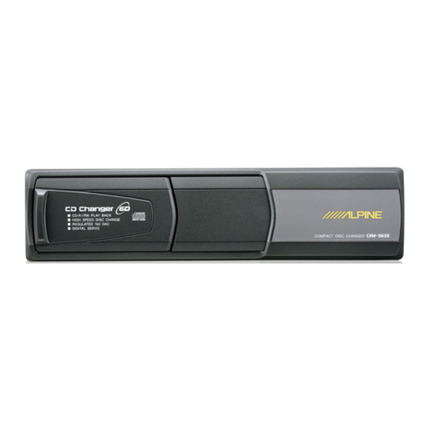
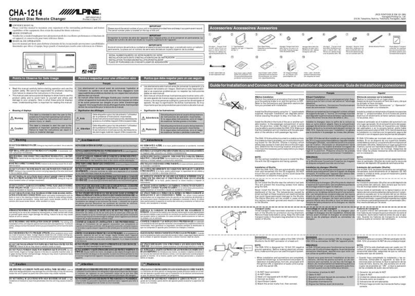
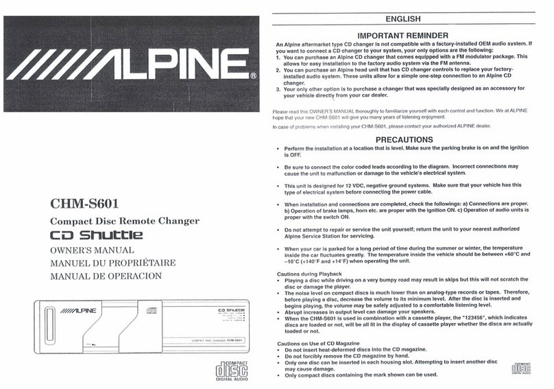
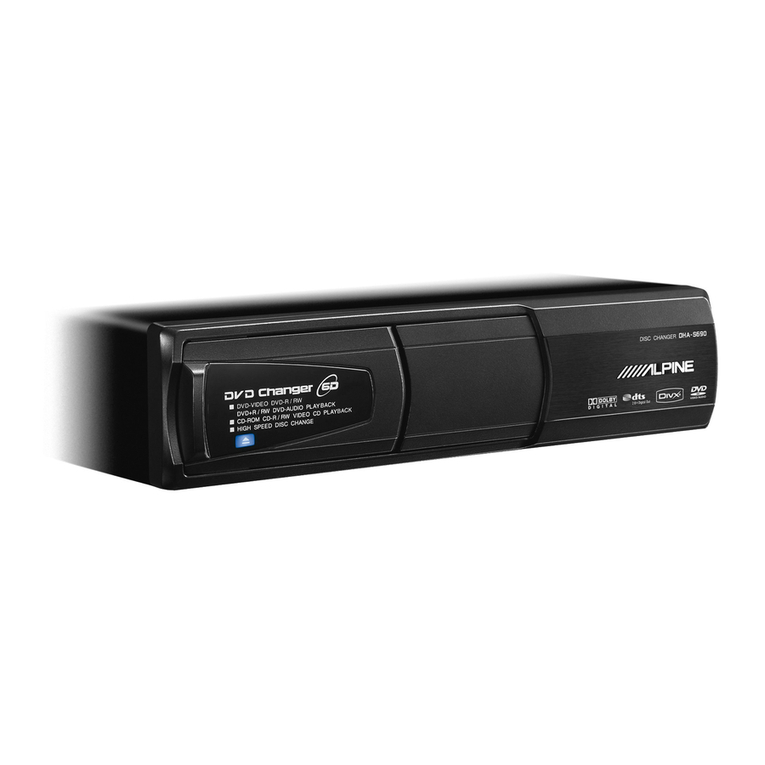
  9. Alpine CHA-1214 User manual

Alpine CHA-1214 User manual

MMMLPINE.
SERVICE
MANUAL
Compact
Disc
Remote
Changer
COMPACT
Cyd)
Shuttle
DIGITAL
AUDIO
@
The
model
described
in
this
manual
is
developed
from
CHA-1204.
For
information
that
is
not
mentioned
in
this
service
manual,
refer
to
the
Service
Manual
¢
CHA-1204
(Part
No.
68E24871S01).
@
For
the
CD
deck
mechanism
parts
(DW74A010)
of
this
model,
refer
to
the
Service
Manual
»
DW
Series
(Part
No.
68E24878S01).
@
SEF
Wis,
CHA-12048°N-ZEFWERDTHW
ETF,
COV
aPV
WHEAOARRMLTEW
ETOC,
RRMCOWTI,
F-EAVIa
FP
Jb
+
CHA-1204
(68E24871S01)
&
BARRA
ET.
@
KIBONCD
X
A=AL
(DW74A01
0)
(CD
TOBE,
t-EAVYIaPJ
>
DW
Series
(68E24878S01)
&
BAAR
ET.
LZ
NINE:
WW
REGULATED
bit
DAC
(HIGH
SPEED
DISC
CHANGE
WOIGITAL
SERVO/
DISC
TITLE
MEMORY
CD
SNLAtie
COMPACT
DISC
CHANGER
CHA-1214
UQB-NET
4-NET
P-EARAIRS|
A
|
Hi
ai
FLO.
Chi
Awana
CHA-1214
Contents
Packing
Assembly
Parts
List
ivi
csiisi
scenes
eatestarwcu
thane
atanca
desks
a
aaa
de
Ret
ih
pede
taae
dines
MEA
as
dices
BEE
RUE
eat
een
ge
cepa
ie
ca
alge
Ota
en
tae
iets
Ailing
ea
led
al
tee
oP
al
tibet,
cash
o
Parts
Layout
on
P.C.
Boards
and
Wiring
Diagram
(Only
Difference)
..........c.cccccccscesscesecesesesecesesssscscsecaecaeseseesecscenens
Schematic
Diagram
(Only
Difference)
.............ccceceesessessssesessesssseensseescsussessssvsusscessssessesausasarsucaesecaesusavavacececsueseceaesess
Electrical’
Parts:
List(
Only
Diflerence)
56ers.
veces
czars
ovens
cicun
cosa
Cesttvesas
sl
asses
ealoaa
eeidiowiaio
dl
cdbloerceg
203s
eaten
Mr
Pay
ie
ci
eagt
ak
she
steer
tet
eee
hil
coca
ala
ERD
ARE
oh
cata
cereale
ae
eaten
saints
coe
Ae
Cabinet
Assembly
Parts
List
(Only
Difference)
.........cccccceccescscscssssesscssscessevscsesusecscseseessavacsusecassescsestsecsuvsssecensesecse
BA
Racy
0
Bl
OR
ae
NAM
re
nc
eae
ye
aa
reel
LCR
g
gO
dae
ea
tc
e
toxin
fen
Gy
Sad
lath
a
Specifications
Servo
Monitor
Fr-REDA-(CDWT
Refer
to
the
Service
Manual
-
Resetting
the
mechanism
elevator
position
CHA-1204
(Part
No.
68P24871S01).
AAIVN—-2-MEOBRE
(CDT
2
Description
of
IC
Terminal
H-ERAVIAP
IL
>
CHA-1204
ca
Block
Diagram
(68E24871S01)
&
SARRAL
Ss
F,
a
Exploded
View
(Cabinet)
:
Semiconductor
Lead
Identifications
i
|
4
Hf
i
rt
No.
33K
01T00733K01
01B90279W01
68P10924Y49
68P10924Y49
68P10924Y67
|
CHA-1214
No.
Sy
Assy.,
Magazine
Ai-NET
Cable
Kit
Installation
Owner's
Manual
Owner's
Manual
(English/Francais/Espanol)
Owner's
Manual
(Deutsch/Italiano/Svenska)
NOTE:
©:
For
North
American
Model
Only,
A:
For
General
Foreign
Model
Only,
Others
:
Common.
1A
tea
aoze
im
aa
01T00733K01
01B90279W01
68P10924Y70
01D90176W01
,
Ai-NET
Cable
Kit
Installation
Owner's
Manual
Assy.,
Magazine
CHA-1214
Parts
Layout
on
P.C.
Boards
and
Wiring
Diagram
(Only
Difference)
NOTE:
Refer
to
the
Service
Manual
*
CHA-1204
(Part
No.
68E24871S01)
for
description
not
mentioned
in
this
manual.
K
aS
nN
TUSuRoCOwTs,
t-EAVIsaPw-:
CHA-1204
(68E24871S01)
&
BARBRA
E
TS,
All
P.C.
Boards
viewed
from
soldered
side.
Main
P.C.Board
REO
WHT)
WHT(2)
WHT(3)
To
CBS01
From
Elevator
PC
Board
(CHS501)
SHLD
(GNO)
SHLD
(S.GND)
2
3
&
AWHT
(BUS-)
2
{Hee
84s
GRY
Festa
|
[ve
arty)
Assy,
AINET
Connector
Connector
P.C.Board
Orange
Color
Pattern
:
Component
Side
P
attern
Blue
Color
Pattern
_:
Foil
Side
Pattern
Le
ens
ee
ee
(ee
Schematic
Diagram
(Only
Difference)
NOTE:Refer
to
the
Service
Manual
-
CHA-1204(Part
No.68E24871S01)
for
description
not
mentioned
in
this
manual.
£113
100/10
s
w+
Main
P.C.Board
*RRENTUSUBBACIUTIA,
F-EAVIAPW-:
CHA-1204(68E24871SOIJZSRMUET.
RIS
47K
R131
15K
C116
8200P
mw
ax
C108
L552
ox
i
sle
ERS
0.1
so
see
oa
=:
ae
ze
ee
Ome
beta
Meo
AUTOMATIC
]
="
2
%)
(28)
LASER
POWER]
X
|
&
CONTROL
ole
0103
2581238
(26)
Ba
=
=
Ls
0102
SB05-05¢P
-ma2
aes
Ee
oT
BUFFER
AMP
R201
R207 R209
6.2K
(27)
E201
R203
C201
100P
g s
in]
2
N
R130
10k
s
8
(22)
3
R113
24K
(21)
R14
1.5K
(25)
R126
15K
(24)
a
a
ee
*
Addendum
Parts
*
IBA
NOTE:
.
1.
All
resistance
values
are
in
ohms.
K
=
1,000
1
2.
All
capacitance
values
are
in
microfarads.
P
=
7,000,000
CHA-1214
CHA-1214
Electrical
Par
ts
List
NOTE
:
For
the
parts
not
mentioned,
refer
to
the
Service
Manual
for
CHA1204
(Part
No.
68E24871S01).
|
Model
|
CHA-1204
CHA-1214
No.
Main
P.C.Board
IC's
1C501
\c502
51T85151W15
51T85304W01
85151W15
X24C16S8!
Capacitors
E106
23774437
C143
—
C144
=|08S82122F61
1pF
/
35V
CP.,
1000pF
Resistors
067T15444W15
06T15444W03
360K
ohm
1/10W
110K
ohm
1/10W
Connector
P.C.Board
Capacitor
as
;
Resistor
R544
=[06S70072F45
CP.,
470
ohm
1/4W
Miscellaneous
M104
]01V83900W16
Assy.,
Spindle
Motor
(2V-90mA)
01V13300Y54
Spindle
Motor
(2V-90mA)
AR
Aab
an
tae
Ic502
|51T85304W01
4X24C16S8l
1pF
/
35V
1000pF
Resistors
06T15444W15
CP.,
360K
92
1/10W
06T15444W03
=JCP.,
110K
2
1/10W
IADR
—
RIB
Capacitor
K
MSH
TUG
RICOUTI,.
t-EAVIAPIL:
CHA1204
(68E24871S01)
<Bh@RRUET,
330K
Q
1/10W
120K
Q
1/10W
ii
23861523F25
ELY.,
0.1pF
/
SOV
23T25191W24
|CP
Resistor
06S70072F45
={CP.,,
4702
1/4W
|
C.F.,
4709
%
MHD
BAB
an
M104
|01V83900W16
[Assy.,
Spindle
Motor
(2V-90mA)
1,390J01V13300Y54
|Assy.,
Spindle
Motor
(2V-90mA)
CHA-1214
CHA-1214
-
Cabinet
Assembly
Parts
List
NOTE
:
For
the
parts
not
mentioned,
refer
to
the
Service
Manual
for
CHA1204
(Part
No.
68E24871S01).
CHA-1204
CHA-1214
|
Model
|
i
a
No.
5-C
[13C90259W02
Assy.,
Front
Escutcheon
Assy.,
Front
Escutcheon
Cover,
Corner
L
Cover,
Corner
L
Cover,
Corner
R
Cover,
Corner
R
Screw,
Pan
Nylok
(M2X5)
Screw,
Pan
Nylok
(M2X4.5)
1-D
}15B90266W02
2-G
|15B90267W02
3
5-
1
5
1-D
]15B90266W01
6
2-G
|15B90267W01
10
03S94385F23
tre
Ry
bP
abanthie
BcM
AN
TUAVBBeaICOUY
Clg,
H-EAVIAPN:
CHA1204
(68E24871S01)
BARRA
ET,
[Model
]
CHA-1204
CHA-1214
ae,
/.o)
ws
[5]
sane
|
az
|omels|
moss
|
was
[sme
cS
|
al]
Bass
Absa
%
EMME]
5!
|
aan
es
abaaS
ENS
3
5-C
]13C90259W01
|{Assy.,
Front
Escutcheon
5-C
113C90259W02
|Assy.,
Front
Escutcheon
2,200
5
1-D
|15B90266W01
1-D
|15B90266W02
6
2-G
115B90267W01
2-G
|15B90267W02
10
Cover,
Corner
L
Cover,
Corner
L
330}
Cover,
Corner
R
Cover,
Corner
R
330}
Screw,
Pan
Nylok
(M2X5)
Screw,
Pan
Nylok
(M2X4.5)
MMMLPINE.
SERVICE
MANUAL
Compact
Disc
Remote
Changer
COMPACT
Cyd
Shuttie
DIGITAL
AUDIO
@
For
the
CD
deck
mechanism
parts
(DW74A010)
of
this
model,
refer
to
the
|
Service
Manual
-
DW
Series
(Part
No.
68E24878S01).
@
KHOCD
X
AHAAL
(DW74A01
O/T
DU
TOBH
ME,
H-EAVIAPVIL:
DWY
\)
—
X
(68E24878S01)
&
SRRRRUYE
T,
MLZ
Nek
INE
COMPACT
DISC
CHANGER
CHA-1204
GGf-NET
Va-NET
P-EZRAES|
OA
|
tt
fi
ALN
.|
MC-53-0
|
ChAwieoa
CHA-1204
Contents
Packing
ASSOMmbly
Parts
List
socccccccicctentask.
icccsencasaesvatensenonctycadenea
onsrenns
shaadosienp
ietuna
iy
tans
oeacweraguvanodhneeentenyacatinatiaddehoays
3
Packing
Method
View
..........::cccccccssesssesescssessesseeescssseessesesssesecsesesecsesecseseesssenseeeseaeesesesesiseesesiseesasessecisieeeesnenstenassaees
3
SPAN
CTE
INS
a
es
oo
chines
Gest
e
paaiace
testa
ined
et
vSdas
see
ied mbt
ect
eaeementeedoones
eed
gota
cay
eategs
Oubathenpe
NRO
seau
Aenea
Satie
4
Servo
Monitor
s-siet
ieieteidiie
eee
tbs
ede
eas.
ntti
Shab
eetee
tht
SRR
Aa
cetera
aol
ang
oa
ae
5
to
10
SF
ee
Fe
GC
ora
ate
eat
ia
cata
tncgatae
A
ccaaaaanepetcana
shes
cdc
cua
bb
eae
clas
en
enue
ee
11~16
Resetting
the
mechanism
Glovator
POSHION
.......ss.sccinisscscscsdsosniyoaaaéasssuausensosscyssepsonssenyospneyavetoreeyensdtokoneredersibnttessaten
17
Fd
EN
ele
Smeg
(7A)
RED
Eo
age
ee
TPR
Ee
EE
EY
STE
nT
nee
nee
eee
ee
17
Description
of
IC
Terminal
.............-:-ccsssessescescsseseseesesssssesesecscsesesecsssecenseseeneessesessssesnsesserstaseesaseecesisereeseeaenens
18
to
19
Block:
Diagram
svtvicscienitnink
fan
idk
eiail
bude
ial
Gatien
eh
Ea
GnRH
aad
tage
20
Parts
Layout
on
P.C.
Boards
and
Wiring
Diagram
...........ceccseceeeeereeeeeeeeseeeieneneneneeeeeeeeneneneneraeeneieeneatenes
21
to
22
Schematic
Diagram
........ccccecceccseecescesesssssscereseesssesseseneesesseesseneeseseessessecseeessenessesseeseeeseessenesneceeeaeareestemeeaeees
23
to
25
ElectricaliParts
List..cs'ccccletszecerssetens
cde
att
sas
eth
dikes
a
caatieadl
ctaadeate
a
sched
deg
apres
aay
betede
nea
aaeeeeae
pees
aeade
26
to
29
Cabinet
Assembly
Parts
List
...........::sccsscscsssssssessssessesssesssssesssevssscescensoesseensseesenessenensesssenessenessasscensesanensensnsaesiy
sees
30
Exploded
View
(Cabinet)
...........ccccecceseecsssessesesecsesesesenscscseseseeeseneeeeeecaseecesiesensenenecasesesieessaenessenanenesnensategs
31
to
32
Semiconductor
Lead
Identifications
..........cccceceeceeseececeeeeeesesceeeneeseceeesceetessetecsersesssseceesersssesseesesaessenessseaeeeesies
eas
33
CHA-1204
Packing
Assembly
Parts
List
No.
No.
:
101
.,
Ai-NET
Cable
Ai-NET
Cable
Side
Bracket,
Mounting
Base
Hex.
Flange
(M6X50)
03B40155F
10
03863857F05
03D40121T11
02B47353F06
68P90579W60
Bolt,
Hex.
(M6X25)
‘|Screw,
Tapping
(M5X15)
Bolt,
Hex.
W/Double
Washer
(M4X8)
Nut,
Hex.
Flange
(M6)
Owner's
Manual
68P90579W60
[Owner's
Manual
(English/Francais/Espanol)
Owner's
Manual
(Deutsch/Italiano/Svenska)
Owner's
Manual
68P90579W61
68P81384W81
NOTE:
©:
For
North
American
Model
Only,
A:
For
General
Foreign
Model
Only,
L]:
For
Japanese
Model
Only,
Others
:
Common.
Packing
Method
View
CHA-1204
Specifications
<CD
SECTION
>
SYStGIT>
es
SocsccactesVcwethl
ba
cetoeia
dea
eceed
cas
Based
tee
Senet
ea
tae
zeace
se
tecs
Lesgube
sesh
cpigtecnvnadacedstutnasie
Optical
(Compact
Disc
System)
Quantizing
Bit
NUMber
oo...
ee
cece
ceeeeseeeseeenecseecaenseseuseaneassesesssesseuseususeeeeassnesseeseesareraseeseeas
16
bit
Linear
System
CHGIAONS
>
©
2555
casksidscd
secebsct
lessee
ala
ueseeccuacesacesavi
desea
oettdeaessuocesuatanssinecess¥ehvoduadescenssooeseeurevsadoeseondied
2
Channels,
Stereo
Ghaninel
Balane:,
-
a.cisefleesssseccescecesecvasescnntdkdveetcscnteces
cozassesencesesaccccossesensvangcuncauceuneensnevesceupaesataisaneedeneayenseiasuaeaueds
0+3dB
Distortion:
(Q9ZZ);
dscibsei
ewes
eecite
wctvavsesieviea
coevese
bse
ehcencipuie
lo
ceteeseveragee
couscedieagensdevieusnedeeatesconea
deapesenloconsadttesebestats
0.02%
Frequency
Response
(Ref.
1KHZ)
oes
cece
eeeceeceesesesseccesseecessesseseeeseeseeeseusesssnenseeuenenenea
O0+2dB
(17HZ~19.997kHz)
SIN
RAO:
.5.pccessevsdevedsacevass
stbeccvaceeysdoeslictl
deed
sieavecd
sveceadunesusveredeesauviucauchvssvavhecsuied
cutaavtigesiecstpagiduevievesesncdunreensers
eee
90dB
Channel:Separation:
~cccvcis
ricceccasiccebis
eke
Ge
cncik
pen
tackceets
raidead
cantencccnsdees
ch
csekesdeesadiegéad
oadsSuba
cerdecebeohasvensote
75dB
(997Hz)
65dB
(10.007kHz)
De-Emphasis:
(Ret.
AKAZ)
—
2:.ccecc.ccdscceccedissscsecanonactetiacsediecotenshadeases
javans
sacacks
gdutnge
tacaschvedeedguleotionecicesece
-20+3dB
(4kHz)
-20+30B
(16kHz)
Corrénts:
Consumption
(at:PEAY):
cstiecsesisisadisessistatecrercescennevstenscectivescadeceavedenicacdcoacoonsvsiacauanedidussbededsedusassteesadunch
ives
1A
<GENERAL
>
POWEr:SUDPIY®
cess
seieestesonceceteuscesnsteh
spunscdcsnesdntionyedoasaugaddust
cnuaneecevastsuavaaeesecaabeasdeeaueaaseasateed
14V
DC
(10.5~16V
allowable)
Output
Voltage
/IMPOdANCE.
.....sccisccceecescicessteevscassavstcscevsacscvecestvosvesestavecesseescetusevsbenseesesetenseees
850
+150mV/10kohm
Semiconductors:
.:..ss5.c:
(escent
cacedindaaes
Geeasxestadsevesbebedh
eanvenasrevensense
cls
12IC's,
13Transistors,
8Diodes,
5Zener
Diodes
Dimensions:(WXHEXD):
sata
nvdadiinedidiviy
ad
beta
tees
dentin
eteadiiitien
aheci
aint
aes
ntesennss
262
X98
x
183mm
WIQNE:
>
sccscccsssssticcecetvenscesteneateaucnssnecaseccaptoyocsupccegadcestsesonsntenseeshcesseesussveegaiedsdi
avseesscUvatvesecavedaaueusoreconsduteviuldearsatdeaiees
2.3kg
<COMPACT
DISC
>
TRACK
PICK
sagssvsscosteacdeves
tases
gueeeidecs
Wlecdhci2i
dy
Aaeesuesvesescectaeesdgustecreececeuieesbersacesveh
atbaatabuceysecesuacsisrseevsebchaaioedhpds
ceautd
16yum
Modulation
Frequency.
c:to:.ssssieiieticcstcsteseseseedientenseesbasectslresasstonus
val
savctausaroeeetdv
ual
eee
dadearbanat
anvleaventesmagiaed
44.1
kHz
Transfer
Rate
-siscseecide
ten
oeaeeieeods
an
ciuensses
edadiehecpuctesdvedh
ovesadauesiisaieayes
cotwetnebiy
ctiara
ts
aneeleted
4.321
8Mbit/sec.
DIMENSIONS:
sesesvekecitccecasechscedicedencecesnncecssetbevsxdsedentesascdies
stedercivesstbasensseds
oPantedipcashoeasbuee
ensntecactipvassuuencyeancon
120
X1.2mm
NOTE
:
Due
to
Continuing
product
improvement,
specifications
and
designs
are
subject
to
change
without
notice.
|
CHA-1204
Servo
Monitor
(Part
No.
01E20845S01)
1.
Purpose
CHA-1204
performs
digital
signal
processing
in
the
inside
of
Super
1
chip
LSI.
The
outside
alignment
circuit
builds
into this
LSI.
Each
alignments
are
automatic.
This
DT
Mechanism
Servo
Monitor
is
a
jig
for
the
automatic
alignment
circuitry.
Please
refer
to
the
following
list
for
the
reference;
1.
LED
indicates
the
alignment.
2.
Diagnosis
of
automatic
alignment.
3.
LED
indicates
a
failure
item
for
easy
failure
analysis
of
servo
circuitry.
External
View
o0vl
©
LPS
VALUE
*
The
numbers
of
the
automatic
alignment
sequence.
ll.
Connection
Points
and
Connection
Method
Main
P.C.Board
(Solder
Side)
T.P.5
(A2)
T.P.3(A0)
Yellow
NOTE
:
For
the
Test
Points
(T.P.3~5),
refer
to
the
Parts
Layout
on
P.C.Boards
and
Wiring
Diagram.
oovl
@
<
Connect
each
of
the
wires
to
the
Test
point
as
illustrated
in
the
diagram.
*
Be
very
careful
not
to
shorts
the
test
points
since
they
are
located
close
together.
CHA-1204
lil.
Operating
Specifications
The
automatic
adjustment
operations
of
the
CHA-1204
are
performed
by
output
of
the
commands
of
the
various
adjustment
items
from
the
main
microprocessor.
Adjustments
are
performed
in
response
to
these
commands
by
the
super
1-chip
LSI.
This
servo
monitor
jig
receives
the
signal
returned
to
the
main
microprocessor
from
the
super
1
chip
LS!
and
causes
the
LED
to
light
or
go
off.
The
adjustment
condition
(of
either
completed
or
not
yet
completed)
of
the
various
adjustment
items
can
be
checked
using
the
lighting
condition
of
this
LED.
The
following
test
discs
are
required
for
the
good/fault
judgment:
1.
A-BEX
TCD-721
(6th
track
-
1.2mm)
:
Scratch
test
disc
2.
A-BEX
TCD-782
:
Signal
test
disc
Measures
to
be
Taken
Corres
1,
When
a
LED
other
than
FAGC
or
TAGC
lights,
perform
the
fault
causation
analysis
using
the
fault
diagnosis
chart
according
to
the
LED
indication.
;
2.
When
only
the
FAGC
or
TAGC
LED
turn
on
a
lights
(indicating
that
the
focus/tracking
fine
gain
adjustment
is
not
completed),
perform
the
focus/tracking
servo
gain
adjustment.
If
the
value
is
within
the
specification,
the
adjustment
is
normal.
i)
LED
indications
Lit
:
Fault
Unlit
:
OK
Adjustment
|
LED
Name|
Adjustment
Order
Contents
Order
AOC2
Tracking
offset
Corrects
the
tracking
error
value
as
an
offset.
adjustment
im:
fo
Ball
d
|
=
|
oer
[omen
pial
earl
ean
cae
AOC1
Focus
offset
Corrects
the
focus
error
value
as
an
offset.
adjustment
4
AGC1
Focus
rough
gain
Determines
the
amount
of
extemal
interference
adjustment
applied
at
the
time
of
the
focus
rough
gain
adjustment.
AGC2
Tracking
rough
gain}
Determines
the
amount
of
extemal
interference
adjustment
applied
at
the
time
of
the
racking
rough
gain
adjustment
ABC1
Focus
balance
Provides
correction
so
that
the
focus
error
signal
can
take
adjustment
balance
between
positive
sections
and
negative
sections.
7
ABC2
Tracking
balance
Corrects
the
average
value
of
the
tracking
error
as
a
balance
adjustment
value.
FAGC
Focus
fine
gain
Introduces
extemal
interference
and
adjusts
the
focus
gain
to
adjustment
an
appropriate
value,
TAGC
Tracking
fine
gain
|
introduces
extemal
interference
and
adjusts
the
tracking
adjustment
gain
to
an
appropriate
value.
ii)
Seven-Segment
LED
(LPS
Value)
This
mechanism
has
26
position
of
1T
to
12T,
1P
to
12P,
E,
HP.
Those
positions
indicate
height
of
elevator
of
mechanism
in
7
segment
LED
in
hexadecimal.
IC501
reads
data
from
these
positions
and
convert
into
A/D
signal.
Hexadecimal
and
tray
location
refer
to
the
following
list.
*
The
1st
to
12th
disc
traies
step
each
1T
to
12T
to
be
drawn
out
of
the
magazine.
The
ist
to
12th
discs
step
each
1P
to
12P
to
disc
chuck
and
play.
E
is
the
position
that
magazine
ejects.
HP
is
elevator
stand-by
position
without
the
magazine.
NOTE
1:
Display
of
each
position
5
value
of
limit
of
HEX
cod,
LPS
(liner
position
sensor)
is
to
rmal.
NOTE
2:
Incase
of
LPS
is
normal
and
disc
change
actuatin
is
not
smooth,
check
magairse
circumference
tray
chasss
again.
CHA-1204
IV.
Fault
Diagnosis
Chart
Main
Flow
Chart
Error
monitor
check
(A)
Fault
item
Judgment
Fault
item
Judgment
TR
balance
offset
adjustment
Offset
adjustment
|
____
41)
balance
adjustmen|
adjustment
bo...
(5)
(AOC2)
not
completed.
(ABC2)
not
completed.
FO
;
F
Disc
:
;
fi
i
FO
fine
gain
F
Disc
detection
fine
gain
:
detection
=>—~-———*]
hotcompleted.
b-----
2
i
adjustment
=
-------
(6)
(DDT)
not
completed.
+2)
adjustment
not
completed.
FO FO
offset
iia,
Ohh
TR
fine
gain
offset
adjustment
adjustment
=
F--=--
<1)
adjustment
adjustment
=
}-----
+6)
(AOC1)
not
completed.
(TAGC)
not
completed.
FO
F
‘
FO
rough
gain
aeicnt
adjustment
=
p=-----
<1)
Does
not
play.
F-----
+7)
(AGC1)
not
completed.
TR
F
i
TR
rough
gain
.
apie
adjustment
-n---
+3)
fr
Soe
Scratched
disc
(AGC2)
not
completed.
playability
play
fault
FO FO
balance
balance
adjustment
adjustment
=
Fe----
-(4)
{ABC
1)
not
completed.
(A)
*
Notes
1)
When
more
than
one
LED
are
light,
perform
a
circuit
check
according
to
the
order
of
the
main
flow
chart.
2)
Proper
soldering
of
patterns
and
IC
pins
is
a
precondition.
Accordingly,
when
an
IC
fault
is
reached
in
the
flow
chart,
do
not
replace
the
part
immediately;
check
the
soldering
(for
loose
and
bridges).
3)
Faults
such
as
faulty
capacitors
and
resistors
in
the
flow
include
bad
parts,
different
constants,
looseness,
and
cracks.
4)
Use
track
6
of
A-BEX
TCD-721
for
the
scratched
disc
playability
check.
Judgments
(1)
TR
offset
adjustment
FO
offset
adjustment
FO
rough
gain
adjustment
not
yet
completed.
not
yet
completed.
not
yet
completed.
Are
the
outputs
from
AN8806SB
(iC
102)
#27,
#29,
and
#30
2.5V?
MN66271
(1C101)
is
faulty
AN8806SB
(1C102)
is
faulty
or
surrounding
capacitors/resistors
are
faulty
*
R102,
103,
104
C109,
110,
122
CHA-1204
Judgments
(2)
Disc
detection
not
yet
completed.
AN8806SB
(IC102)
#27
FEOUT
Is
there
output
of
an
S-curve
?
MN66271
(10101)
is
faulty
Judgments
(5)
‘TR
balance
adjustment
hot
yet
completed
(16101)
#31
25V?
AN8806SB
(IC
102)
is
faulty
or
surrounding
capactors/resistors
are
faulty
Is
there
laser
current
?
APC
circuit
is
faulty
v
Laser
current
=
0
(A)
*RI41
YES
Note:
Do
not
connect
or
disconnect
a
DC
voltmeter
while
the
set
is
drawing
current.
Doing
so
may
destroy
the
laser
diode.
Is
the
laser
current
within
+5mA
of
the
indication
on
the
flexible
wiring
*
Internal
temperature
of
the
set
is
room
YES
temperature
(20°C)
Does
the
objective
lens
of
the
pickup
move
up
and
down
?
AN8806SB
(C102)
is
fault
or
surrounding
capacitors
/resistors
are
faulty
(R104
,
C122)
Isa
triangular
wave
of
MN66271
MN66271
(1C101)
is
faulty
triangular
waves
of
BA6791FP
{1C103)
#26
(4.1V)
and
#27
(3.8V)
utput
2
BA6791FP
(IC103)
is
faulty
YES
Pickup
is
faulty
*
Focus
coil
is
open.
MN66271
(1C101)
is
faulty
*R102
cno
Judgments
(3)
TR
rough
gain
adjust-
ent
not
yet
completed,
AN8806SB
(/C102)
is
faulty
or
capacitors/resistors
surrounding
TEQUT
are
faulty
*RIOS
C123
MN66271
(iC101)
is
faulty
Judgments
(4)
FO
balance
adjustment
not
yet
completed.
Is
the
Does
the
output
of
focus
servo
INGE:
MN66271
(IC
101)
come
on
?
eceeT|
Ue10))
#28
26V?
*
Is
the
output
of
MN66271
(IC101)
YES
#11
(FLock)
“L'?
Is
the
output
of
MN66271
(16101)
#28
2.5V7
Does
the
tracking
servo
come
on
?
MN66271
(IC
101)
is
faulty
*
Is
the
output
of
MN66271
(IC101)
YES
#12
(TLock)
*L"?
External
capacitors
of
AN8806SB
(IC
102)
#11
and
#12
are
faulty
or
AN8806S8B
is
faulty
*CIL2,
113,
118
NO
Is
the
output
of
MN66271
(1C101)
#30
2.7V
2
AN8806SB
(IC102)
is
faulty
or
surrounding
capacitors/resistors
are
faulty
*
R103,
C109
BA6791FP
(ICt03)is
faulty
or
surrounding
capacitors/resistors
are
faulty
*
R116,
917,
118,131
Cii6
E131
*
Focus
coil
is
open
or
tracking
coil
is
open
Judgments
(6)
FO
fine
gain
adjustment
not
yet
completed.
TR
fine
gain
adjustment
not
yet
completed.
Is
the
gain
normal
7
MN66271
(IC101)
is
fautty
Both
focus
and
tracking
are
within
0
+
3.dB
is
the
external
CR
fitter
circuit
normal
7
Pickup
is
faulty
Extemal
CR
filter
és
faulty
(4A,
CHA-1204
Judgments
(7)
Judgments
(8)
Faulty
play
of
scratched
disc
External
CR
fitter
of
tracking
servo
system
is
faulty
Unit
does
not
play
External
capacitor
of
AN8806SB
(IC
102)
#13
Are
the
is
faulty
outputs
of
:
*
R105
C123
wN6B2¥1
(10101)
MN66271
(IC101)
#44,
prereset
ag
R16,
1R
eR
EV?
#45,
#47,
and
#48
C16
*R109,
110,
111,
112
R131
+
#44---2.6V
}
CIOL,
102,130
EI3I
#45---15V
TEBPF
circuit
between
#47--2.6V
#25
and
#23
of
#48---2.1V
AN8806SB
(IC102)
is
faulty
*RI06
,
124
C107
,
108
Are
the
outputs
of
MN66271
(C101)
#13,
MN66271
(IC101)
#14,
and
#15
is
fauly
*#13—-0.1V
#14---4.9V
YES
#15
---
4.8V
Microprocessor
(IC501)
is
faulty
Drive
unit
or
pickup
is
fautty
Measurements
A.
RF
Signal
Level
Measurement
The
main
beam
of
the
returning
light
is
received
by
the
photodiode
and
the
output
voltage
is
obtained
by
current-voltage
conversion
of
A+B+C+D.
1,
Block
Diagram
Sample
player
Oscilloscope
2.
Measurement
Method
(a).
Connect
the
ground
terminal
of
the
oscilloscope
VREF
(AN8806SB
(iC
102),
PIN
20)
and
measure
the
RF
signal
(of
AN8806SB
(IC
102),
pin
7).
(b).
Play
the
first
track
of
the
measurement
disc
A-BEX
TCD-782.
(c).
Read
the
peak-to-peak
value
of
the
waveform.
Specification:
0.5V
+0.2
*
When
the
value
is
outside
of
the
specification
(i.e.,
not
good),
check
AN8806SB
(IC
102),
the
pickup,
and
R136/C120.
B.
Jitter
Measurement
The
standard
deviation
of
the
pulse
width
when
a
trigger
is
applied
to
the
rising
edge
of
the
3T
component
of
the
RF
signal.
1.
Block
Diagram
Sample
player
Jitter
meter
2.
Measurement
Method
(a).
Connect
the
ground
terminal
of
the
jitter
meter
to
VREF
(AN8806SB
(IC
102),
PIN
20)
and
measure
the
ARF
signal
(of
AN8806SB
(C102),
pin
10).
(b).
Play
the
first
track
of
the
A-BEX
TCD-782
measurement
disc.
(c).
Read
the
indicated
value
of
the
jitter
meter.
Specification:
25nS
or
less
*
When
the
value
is
outside
of
the
specification,
check
AN8806SB
(IC
102),
the
pickup,
and
R136/C120.
CHA-1204
C.
Focus Servo
Gain
Measurement
Measure
the
focus
servo
open
loop
gain
in
the
servo-on
(closed
loop)
condition.
1.
Block
Diagram
Sample
player
Oscillator
and
oscilloscope
2.
Measurement
Method
using
an
Oscillator
and
an
Oscilloscope
(a).
(b).
3.
Connection
(Example)
Connect
OSC
output
to
resistor
for
gain
measurement
(100
ohms).
(Connect
a
servo
driver
side
to
positive
side.)
Connect
CH1
of
oscilloscope
to
a
servo
driver
side
of
resistor
for
gain
measurement
(100
ohms).
(Connect
negative
side
with
GND
of
set.)
Connect
CH2
of
oscilloscope
to
MN66271
(IC
101)
side
of
resistor
for
gain
measurement
(100
ohms).
(Connect
negative
side
with
GND
of
set.)
Play
back
the
eighth
track
of
A-BEX
TCD-782
disc
for
measurement.
(No
sound
recording
track)
Output
frequency
(1.2
kHz,
150
mVP-P)
from
OSC
and
compare
the
amplitude
of
CH1
and
CH2
of
oscilloscope
and
convert
into
dB.
NOTE:
AC
voltmeter
is
available
to
measurement.
OSC
Oscilloscope
or
AC
voltmeter
Common
with
the
ground
of
the
set
BA6791FP
(IC
103)
*
FOD:
Focus
drive
output
D.
Tracking
Servo
Gain
Measurement
Measure
the
tracking
servo
open
loop
gain
in
the
servo-on
(closed
loop)
condition.
1.
Block
Diagram
Sample
player
Oscillator
and
oscilloscope
2.
Measurement
Method
using
an
Oscilloscope
(a).
(b).
(c).
(d).
e).
Connect
OSC
output
to
resistor
for
gain
measurement
(100
ohms)
connection
(Esme)
(Connect
a
servo
driver
side
to
positive
side.)
Connect
CH1
of
oscilloscope
to
a
servo
driver
side
of
resistor
for
gain
measurement
(100
ohms).
(Connect
negative
side
with
GND
of
set.)
Connect
CH2
of
oscilloscope
to
MN66271
(IC
101)
side
of
resistor
for
gain
measurement
(100
ohms).
(Connect
negative
side
with
GND
of
set.)
Play
back
the
eighth
track
of
A-BEX
TCD-782
disc
for
measurement.
(No
sound
recording
track)
Output
frequency
(1.2
kHz,
150
mVP-P)
from
OSC
and
compare
the
amplitude
of
CH1
and
CH2
of
oscilloscope
and
convert
into
dB.
NOTE:
AC
voltmeter
is
available
to
measurement.
OSC
Oscilloscope
or
AC
voltmeter
Common
wth
the
ground
of
he
set
BA6791FP
(IC
103)
*
TRD:
Tracking
drive
output
-~10-—-
|
CHA-1204
RES
Y
—
(2
OVT
(Part
No.
01E20845S01)
L
BAY
CHA-1204
CIE,
FY
¥
ig
5
MLE
&
Super
|
chip
LSIN
CLE
LTB),
FEO
SELES
COLSIAICAR
SNH).
SRMEDAMCHEONTHIETF,
<=
ODT
Mechanism
Servo
Monitorlt,
CNSOAHMBAIEBEHEL
TRADEHETS
GAC.
WFOMRBEREVET.
L
PEDERI
ARONKDERRLET,
oe
aa
OE
ET)
ABGIRA
£LEDRARL.
Y-
KROL
RR
CABICLET,
AM
Bt
ES
MUAPINE
LPS
VALUE
*RRAOKFIL,
ASIN
t
BRLET.
dei
4
Yb
&
Re
RETT
IE
24
7
JAK
CEU)
ARIBATT)
TP.S(A2)
@
TP.3(A0)
.-——
FCLOCK)
Bi(DATA)
OT
Mech. Servo
Monitor
3.5
6
°
RTA
PAHS
bh
(TPH
TP.
5)
12D
is,
Parts
Layout
on
P.C.Boards
and
Wiring
Diagram
cBRBOET,
MUN
PINE
LPS
VALUE
BIAV—-
EMORY
AARETS
|
KFARRAY
PAYTHELTVAZADGYa-kLEWE
SNR
LTFAY,
|
a
es
CHA-1204
|
III.
VETER
CHA-12040
BBDMBSES,
AAV
IY
POBMBRABOIVY
FEWLA-N-1lF
yy
TLIC,
TOIVY
FIG
CHET
AEDT,
COUV-REAWY-BARI,
Z-N-1F
V
FLISIPS
AAV
VA
AVRO
TAREE
SV
LEDER
OLA
TSA
HET.
«=
COLEDORNKEIC
LO,
See
MIKE
(SET
/A5E
TT)
&
RR
HTEMMRET.
ROWE,
KOFAFIATALECT,
1.
A-BEX
TCD-721
(6HHE1-1.2mm)
:
AVF
YFFAKF
AA
2.
A-BEX
TCD-782
RF
RREIAY
1.
FAGC,
TAGCLFOLEDA
AKT
L7BF
lS.
LED
RIC
flo
CTR
RSF
+ —
hI
LOR
RR
ETS
OT
Fav,
2.
FAGC,
TAGCCOLEDO
ARK
LLBEA(7
4
-HA/hF
YY
THACCHBASET
IL.
TA-WA/RGVARYT
POR
AVERT
ROTARY
IACHNIZERTT.
i
LEDIZ
DVT
HATING
=
PLAT:
0K
no
pe
ee
et
Pa
ieee
TE
(ale
ems
eee
i
i
[ee
TW?
4
7
ABBE
OLE
R
y
a‘.
ae
3:
Ao
PART
BRM
BRM
cum
hay
282
Jer
OBIE
SF
v
2
fei
Ed
itehera?
omnes’
=
a
ae
ann
he
ee
ae
Ps
aca
ii)
7&7
2%
Y
BLEDIZ
V2
T
(LPS
VALUE)
AL
AWE,
IT~12T,
1P~12P,
E,
HPOWBKRY
Ya
veHoTwEt,
TOCTLFAY
HLEDILEY
AAOLLW—
Se
16E(KEI-
P)RRRLEF,
LPS
(VET
RY
Yavyevt—)
LOB
ONKF-FEICGOOVI
A
VARA.
ADRS
S.
COIL
OUKA~LMAOF
1
AZ
SSRAWEROTL
1
EEL
TIY:
7
bie
MSIE
MHREF,
FRILL
HL
AMBOMOERTT.
*1T~12TIL,
TNEHNIB~1LIBOF
AAD
RVARVAY
YOUR
RV
av
1P~12PIk,
TNEHNIG~lLIBO
TF
1
AVEF
VL
IEYIL,
PLAYT
ARV
VY
av
Ela,
VYYYeEJECTC
ARV
Y
avert,
Hid,
VAY
VY
ELOBROLLA—¥-ORRMETCT.
as
ce
ae
BE
aes
ae
ae
ae
ee
ee
eee
ee
ee
a7
eee
eae
aa
w-8
|
el)
SRY
LY
a
vILPMT
oS
RRAHEXI—
FB
Eee
=
DRBAME
CH
NIX
VAT
RL:
>
mec
a
ey
(LPS)ILER
CH.
=a
ar
72)
LPS
(VET
HRY
Yavevt—)
o3E
ne
a
ae
LPPDOEP
IA
APF
ay
JOA
20S
ae
ee
_
RAAF
ADNBVIL,
VHLD
/
fe]
Tee
=
RL
A
Ye
—
SEI)
OME
ET
Ron
Fa
1
3
2
3
2
J
62
4
4
4
~12-

Other manuals for CHA-1214

2

Other Alpine CD Player manuals

Alpine CHA-1214 User manual

Alpine

Alpine CHA-1214 User manual

Alpine CDE-136BT User manual

Alpine

Alpine CDE-136BT User manual

Alpine 7915M User manual

Alpine

Alpine 7915M User manual

Alpine CHM-S630 User manual

Alpine

Alpine CHM-S630 User manual

Alpine CHA-S624 User manual

Alpine

Alpine CHA-S624 User manual

Alpine S690 - DHA - DVD Changer User manual

Alpine

Alpine S690 - DHA - DVD Changer User manual

Alpine S634 - CHA CD / MP3 Changer User manual

Alpine

Alpine S634 - CHA CD / MP3 Changer User manual

Alpine DHA-S680 User manual

Alpine

Alpine DHA-S680 User manual

Alpine 5900 User manual

Alpine

Alpine 5900 User manual

Alpine CHM-S611 User manual

Alpine

Alpine CHM-S611 User manual

Alpine CRA-1667RF User manual

Alpine

Alpine CRA-1667RF User manual

Alpine DVA-5205P User manual

Alpine

Alpine DVA-5205P User manual

Alpine 7906R User manual

Alpine

Alpine 7906R User manual

Alpine DS Series User manual

Alpine

Alpine DS Series User manual

Alpine CHM-S620 User manual

Alpine

Alpine CHM-S620 User manual

Alpine CHM-S652RF User manual

Alpine

Alpine CHM-S652RF User manual

Alpine S690 - DHA - DVD Changer User manual

Alpine

Alpine S690 - DHA - DVD Changer User manual

Alpine 7980M User manual

Alpine

Alpine 7980M User manual

Alpine 3DE-7887R User manual

Alpine

Alpine 3DE-7887R User manual

Alpine CHA-1204 User manual

Alpine

Alpine CHA-1204 User manual

Alpine CHM-S665RF - CD Changer User manual

Alpine

Alpine CHM-S665RF - CD Changer User manual

Alpine DP-S Series User manual

Alpine

Alpine DP-S Series User manual

Alpine CHM-S630 User manual

Alpine

Alpine CHM-S630 User manual

Alpine CHM-S601 User manual

Alpine

Alpine CHM-S601 User manual

Popular CD Player manuals by other brands

Pioneer CMX-5000 Service manual

Pioneer

Pioneer CMX-5000 Service manual

Sony CDP-CX235 - Mega Changer operating instructions

Sony

Sony CDP-CX235 - Mega Changer operating instructions

Sony DVP-FX720 operating instructions

Sony

Sony DVP-FX720 operating instructions

Sanyo MCD-ZX530F Service manual

Sanyo

Sanyo MCD-ZX530F Service manual

Sony CDX-C7000X - Fm/am Compact Disc Player operating instructions

Sony

Sony CDX-C7000X - Fm/am Compact Disc Player operating instructions

Sony CDP-D12 Product information manual

Sony

Sony CDP-D12 Product information manual

Sylvania SKCR2713-AM instruction manual

Sylvania

Sylvania SKCR2713-AM instruction manual

auna RCD320 instruction manual

auna

auna RCD320 instruction manual

Teac SR-L100 owner's manual

Teac

Teac SR-L100 owner's manual

Philips AZ8075 - Portable Radio Cass Rec Bedienungsanleitung

Philips

Philips AZ8075 - Portable Radio Cass Rec Bedienungsanleitung

Marantz CD5004 Service manual

Marantz

Marantz CD5004 Service manual

Sony Discman D-465 operating instructions

Sony

Sony Discman D-465 operating instructions

Yamaha CDC-625 Service manual

Yamaha

Yamaha CDC-625 Service manual

Philips/Magnavox AZ 7330 owner's manual

Philips/Magnavox

Philips/Magnavox AZ 7330 owner's manual

Sanyo CDP-S4900 XE Service manual

Sanyo

Sanyo CDP-S4900 XE Service manual

Philips AX 1100/00 user manual

Philips

Philips AX 1100/00 user manual

Sony WALKMAN D-CS901 release note

Sony

Sony WALKMAN D-CS901 release note

Lenoxx CD-155 operating instructions

Lenoxx

Lenoxx CD-155 operating instructions

manuals.online logo
manuals.online logoBrands
  • About & Mission
  • Contact us
  • Privacy Policy
  • Terms and Conditions

Copyright 2025 Manuals.Online. All Rights Reserved.