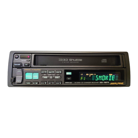
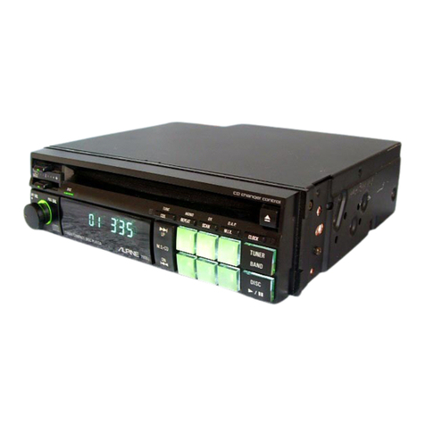
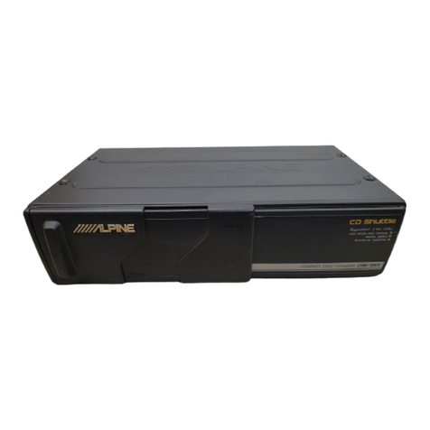
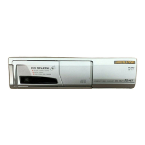
Alpine 3D Shuttle 7982R User manual

JUUALPNE.
SERVICE
MANUAL
FM/MW/LW/RDS
In-Dash
CD
Changer
3D
Snuttie
ofr
@
For
the
CD
deck
mechanism
parts
(DS24A020)
of
this
model,
refer
to
the
Service
Manual
e
DS
Series
(68P50238W02).
7I8AIR}

7982R
Contents
SPOCHIGATIONS
x.cicccssce
cesnscesedbed
ad
spesSebatbewsacls
eede
cleanse
op
readin
Gasd
eG
ieend
sede
ea
ececte
Coauceeted
sees
stuoeb
cBeddevsuecendginsccesn
sevetesteeseaeseeyess
3
to
4
I
Case:
Of:
Difficulty:
ase:
savcetsscs
scdeascevecaced
Soesbea
avetbabesl
lalectehesials
cavstedeaciietsclyeapeneSecdtensasadoaeas
saovebuseduemsecevdesocceapncdvenendosuedtuey
5
to
6
indication
foro
Shuttle
2a.
cigs
cecitacvieeteesavacetesscdiccs
leant
arorineshopedaws
passive
an
eeeas
ae
eke
eae
aay
cuecadeatialsen
ene
6
COMME
CHONS
Fi
sescscalechectasicn
cs
Sietig
le
dellea
nh
eeva
ta
canscasudi
dua
oscuackotatin
lean
vvsalesev
cauccbstevedeceuenvensesdedossessciveniveteeedeawees
deQlevansesbesadae
7
to
8
Detachable:
Front:
Pamela
sccccticcsdesncecoxeteseacechined
ctledeces
Usvendeactausssscieccbanndoodpaeesasscdbecesedesusteonuevanseussbessesaveseaysnecpsudectsedesessvanapesetes
9
Anti-Theft:
OD
OratiON
x.
scccassscecccaets
secdessecuenadeiw
cca
Sucede
Cech
cechuacinesvascelgugisadecacteaselacesecttesestaceedaegesaieieclassvancesscecsebanobecssvesdsuces
9
to
10
BaSic
QPS
ration
ess
sise
ease
a
foecatsnc
Sesteepses
dices
natcuauaiiessbdedcswinvaa
sascsbedudconsecathvsstancegasedacseedecessea¥unsancedtscavacusessbadeeseserentss
10
to
11
RAGiO
Operations
20:
si
c5esveccssevcudesssscsstecdeusceuicasecuesashevavuenosiscuassivcsdcuebscsedescdenestuessoedtveds
suavedesecaccesdevedanvecestesedeccetesiveseens
11
to
12
CD
Operation
ceicccaseiecca
cab
ccts
Si
leced
ele
sece
a
Gciid
eat
anpesiu
ea
bacieae
ac
cdvesacstbuge
lessaceuctcesdeslislede
sQuuavabeaiadeosayovay
hdvnatedi
as
ssessh
colesteets
13
to
14
COCK
OPO
ON
ores
sca
502k
seta
sce
Sten
codec
neklcute
ace
odvaducs
suuaseusliansssiaaccessdsucsevesuedecsesteeu
sheds
cceudesescabiedesas
dentate
siceentesdecessl
tedesbesereuatays
15
RDS...........
Ducsd
esc
aueadtsataigaaedsaiiuwsecaued
cata
Deada
vac
aa
Faek
pubes
dau
ead
duis
osu
ta
vnc
beubu
eghsdunndSvebcaseatevsetavatesaeta
vse
sdesstatereus
cvbanedudiatsundetucevadige
15
Setting
RDS
Reception
Mode
and
Receiving
.0...
ee
sssceessneesseecsscesssssssenevseessenesessesesecsasssaveecasesceesasesseaseaneenereusnes
15
to
16
Recalling,
Preset:
RDS:
Stations:
aici.iz.zecceckedsea
cdots
cd
sabcdadaten
sbi
Siticee
ceed
aie
dassGuspde
custnaiadielentursndateaiedbviesnciadveseeslsenttoceasdetosteznars
16
Receiving
RDS
Regional
(Local)
Stations
.......cceeecsssesseseececsecesesesseseeressessnenseessessrsessensesesseassenssenasenes
oystieseattaersuisieters
16
Receiving
Traffic
fintrITAANOR
ces
auceyecsest
eaten
echt
ccea
tt
ett
Me
Fda
ca
irae
hs
careeer
ee
anna
ennemn
aA
17
Receiving
Traffic
Information
While
Playing
CD
or
Radio
..........ccssssesseccsseeseesesecsecseesesessarencsensecarsecsseaceessaecaeesetseeseesenenseana
17
Presetting
Volume
Level
for
Traffic
Information
........cccsscsscssssessssssessessscsessessesseeseseusesssessenssssesesaseceesendcaseeesecastsensaraaesennease
17
PTV
sTQUAUG
sis.
des
see
eceisn
ceeeises
ceicieas
gahco
Besta
beczacs
dys
casdiuatsya
sbdeted
sSeussscice
cath
vacesbovaccsetsa
dete
ckatada
slevedsnstdeedasesteeesacdscuaetueice
exeaseeesB
card
17
DiSasseMbly'
INStruCtions:
sssisciedccsszisesecdesaseacschsesdseacsesscvedusiseslesanethsacgeseusonssdesecaea
Goveaestees
seevocedocunsgeteiadatuobstasucedewranedantee
18
to
19
Adjustment:
PrOCGQUIeS
.
sisencic
cect
sessceceetbetecsdteterenssnisaetaccaussuasteybeesecnsdek
abv
enestncueds
oadae/seubcuicuusaude
chet
eaaisonadeebalbavetcessosbuceas
20
to
23
Adjustment
LOCAtONS.
scscccsescsscsssncsceeveadabadeesdevcaceseasbcnacicnssednacueanansazciesbehgessecuaassnseedveeansasvanodensasebeerseeceus
duatanetendecduwwiaais
24
to
25
Description:
of
IG
Terminal
ccccisiscvsesescsscsbbessedocsssesuescvocscesscsssgvevecasscvecesoesepnescesgessssevundbacnsetevavse¥asdatvassesevecveneayasssaiasséne
26
to
30
ECD
DISPIAY
ca
ccesitecctecsstevivehaleasdetdtewess
tw
eetensbvalevecebce
useds
chdsast¥ndistl
scuuansdesusaubeattunvoni’eceesGsdeeseeds
Ueda
esobaiedetens
shatesdepsecetessdseaientelens
31
Packing
Assembly:
Parts
List
cc)
ics
sice
cielo
lac
n
ee
decd
tbat
dares
cg
cis
cavenenase
donbses
caducdhcumnsecsoSdeceslecischudns
sottiacd
cteaaeralbcecwens
32
PackinigiMethod
View
ivcsiescesccssicecivegectices
pucutesctepsteteadsvectecsseccevebosecnanShwecthdutcuacbetcescucdedceunecsdnilsdcsvitedenececditvteeasdueveevseucadhganste
32
BIOCK:
DiaQrain
incase
cictcssentbc
ccscresdan
eteeesenedieaeh
dieatiaet
dei
sSectliasebeudsadeiuectavensdsauedudedaedoapccusducecdssasraadieatiiedersestunepeavedseaseacvoseounsen(s
33
Tuner.
Schematic:
Diagram
xc.
ccevivessacetecsesedeeeseysvss
tae
sasckdet
asesecladocccseusesten
dudeiie
duchacuneedaceuvebebaesioseatsldeattsucecsebobedacsunseceteabenest
34
Parts
Layout
on
P.
C.
Boards
and
Wiring
Diagram
(1/2)
oo...
cccssscscsscseseesesesenecsesenenseessenssseseesseessesesesseacueseesesesrens
35
to
37
Parts
Layout
on
P.
C.
Boards
and
Wiring
Diagram
(2/2)
.......sccessssscssscecssssesecsecseccssesstecsenesseatecesessescenaeeaseestesenees
38
to
40
Schematic:
Diagram:
(1/4):
-cccc.scccdeweivcc
seasiseceaalichae
set
casecctebeesadedectavsesuscocsssebuvesteccedecedscdsteussscensesuseuansuslessivsaredtesecessaseas
41
to
43
Sohematic
Diagram
(2/4).
cszsscccesssteecesdeattieeeetiecsesteorte
cadecagvbesbasessscsiesscocdesvehInesesocedetessoscvietered
Qurdyseatbetteaevesvassuctansuseets
44
to
46
Schieriatio®
Diagreny.(B/4)
sscccsscedes
Lateeccecectesdeceeesapceeceytesk
couch
dk
cvece
sua
casted
vesacve
lev-vesecsduegcevevedseveveueh
veveesdelte
ates
euetubebaleseces
47
to
49
Schematic
Diagrary
(4/4)
csiccstsscsedevecessceselindsececsenstestentonsstevessselerensevevouecdereuevetegssee¥ecesvsedenveedsepen
cisentsvesttoeesnesbeensaensbe
50
te
52
Electrical’
Parts:
List
cc
cce.cccccscedascsecacs
tacevesssaesieeegcietids
dadsesa
etesesduess
cleaaba
sh
cuacedsasheviassacevaceodsaudyicsuiiueulrsurastucscecesSegdetesteaseea
53
to
63
Exploded
View:(Cabinet)
(1/2)...
.cccsssstissecdeasneces
sctcetedeceastesldsesicveisassusicdbsceadevouv
scans)
saivecbeidevavesdaacuesgutusaveccdalavalis
duedvees
65
to
66
Exploded:
View
(Cabinet)
(2/2):
ssi.
cccstcacsscsnslesscadessessecee
cedvebeseionsseabove
cused
sndes
avededesceapvesuaesdededay
scpense
cgeseb
onsvccasesiecsearesteevessous
67
Cabinet
Assembly:
Parts:
List
...202.5.0.cs.sscicsasscxcasecbcacts
oueate
naz
seseyocasleee
se,
Sucdedausbuacas
te
cdeseitassveaba
caeaatavssall
eatsdedlaag
al
ewalacesnsivesene
67
Semi
-
Conductor
Lead
Identifications
..........cccssssscseesseesecesesseseerevsceseececseescaseencaseeeeacenereececessteaseassaseaeseeaesaneassoeenee
68
to
76
Spare
Schematic
Diagram
Inserted.
7982R
Specifications
<CD
SECTION>
Oe
1
eon
Optical
(Compact
Disc
system)
Quantizing
Bit
Number
.......
0...
cece
cece
eee
een
n
teen
ene
n
eee
eee
e
eres
e
eer
en
neers
20
bit
Liner
system
Chaninels:
fooscebasceo
codon
ucea
ns
leleve
ota
doecd
ib
Sanden
eee
Shane
wie
eM
hea
ie
CREE
Maials
ccatele
eeiletie
via
Mla
relate
g/g
Gels
gt
a4
2Channels
Channel
Balance
(1KHZ)
....
ccc
ccc
ccc
cece
eee
cence
ee
een
e
REE
en
eee ene
ERE
EERE
EEE
eee
rE
earn
aes
anne
es
0+3dB
Distortion
(1KHZ)
0...
ccc
cece
cece
ce
eee
eee
ete
Eten
EERE
EEE
ee
teen
ene
Er
EE
se
eee
eee
nese
eee
nas
0.1%
Frequency
Response
(Ref.
1KHz)
20.0...
cece
cece
cece
ere
ener
e
ener
e
tne
eect
nee
ee
ent
etenaeee
17Hz
:
0+3dB
127Hz
:
0+2dB
10.007kHz
:
0+
2dB
19.997kHz
:
0+4dB
SIN
Ratio
(1HZ))
soca
x
ccees
coed
eed
vale
kos
dencae
cae
nde
ese
Ones
Seaeaeue
bide
eae
oes
ee
beg
ey
Hele
owe
eh
ete
e
be
hese
els5
85dB
Separation
(1KHZ)
...
ccc
cece
ee
ence
eee
nee
eek
eee
rece
ere
eet
e
Ee ee
tensa
EE
Eee
ene
EEE
eter
e
ge
eee
anaes
70dB
Noise
Level
(at
Volume
Min.)
......
0c
cece
ce
eee
eee
renee
en
ene
eee
eee
ee
EEE
eee
een
r
eee
seen
sean
a
es
0.1mV
Currents
(at
PLAY)
22...
ccc
ccc
ccc
eee
ee
ee
eee
eee
eee
een
e
en
ee
eee
EER
eRe
nee
Ene
eee
eee
eee
t
eet
1.2A
De-
Emphasis
(Ref.
1KHZ)
.....
cece
cece
ccc
eee
cece
eee
renee
eaten
ene
ete
teense
nee
e
tenet
ene
enees
4kHz
:
-
20+
3dB
16kHz
:
-2043dB
<FM
SECTION>
Intermediate
Frequency
.........
cee
cece
cee
eee
een
nee
n
nee
tenet
e
nett
ence
erence
en en
seen
neers
10.7+0.1MHz
FreQUeNcy
RANGE
.....
cee
cece
eee
eee
eee
ene
eee
n
enn
eee
rene
een
ene
seer
nese
teen
e
teeta
es
87.5~108MHz
Usable
Sensitivity
(Mono,
98.1MHz,
30dB
S/N
Sens.)
.......
0s
cece
eee
e
eee
tenn
ete
ene
een
e
ene
n
nen
ene
17.20Bf
-3dB
Limiting
Sensitivity
(Mono,
98.1MHZ)
........
cece
ee
eee
ree
tree
een
eee
eee
n
ete
n
ete eee
nee
n
ee
tnn
eens
19.2dBf
S/N
Ratio
(Stereo,
98.1MHZ)
.......
cece
cece
cece
cee
ener
rete
een
e
nent
n
teen
ener
ener
n
sete
teteeneeeraenee
56dB
Image
Rejection
(106.1MHz)
......
0.0
cece
eee
cere
een
en
eee
eee
e
eee
e
teeta
e
enter
een
ene
E
seer
ee
een
nee
as
.
40dB
IF
Rejection
(90.1MHZ)
........
cece
eect
cee
ee
nen
e
enn
eee
beeen
eee
e
eter
e
eee
e
ete
te
ener
ate
n
ee
eae
en
eees
60dB
Distortion
(Input
GOdBY,
98.1MHZ)
........
cece
cece
cece
eee
erence
reece
eee
n
eee
e
ee
een
etree
erenennnn
eee
aete
1%
Frequency
Response
(98.1MHz,
Ref.
400HZ)
......
0...
cece
cece
ene
e
eee
cence
eet
e
crete
ee
en
enn
tneeas
100Hz
:
0+3dB
10kHz
:
-12+3dB
Stereo
Separation
(1KHZ)
.......
cece
cece
ce
renee
nee
e
eee
e
ete
e
ene
e
enn
eee
e
eee
e
eens
enn
e
sneer
seen
en
eees
20dB
Residual
Noise
(98.1MHz,
Ref.
400HZ)
........
cece
cece
ce
ete
e
ene
e
eee
teen
eee
eens eres
ete
eaentaes
30+5dB
PS
Sensitivity
(9B.1MHZ)
2.0.0...
cece
cece
ete
erent
n
eee
e
eee
e
eee
nen
een
ence
terete
ee
eae
e
ena
e
eaten
eset
eaas
36.2dBf
TP
Sensitivity
(98.1MHZ)
....-..
cece
cece
ccc
ee
ene
tener
enn
E
een
ene
ene
ete
nT
tree
een
nese
een
e
eae
ees
36.2dBf
<MW
SECTION>
Intermediate
Frequency
2.00...
ccc
cece
cern
eee
nett
een
eee
nee
e
eee
e
eee
nat
neste
n
aes
450kHz
Frequency
Range
.........
cece
cece
eee
eee
renee
ence
eben
een
eee
esse
eaten
eeen
eres
reese
enes
531~1,602kHz
Sensitivity
(20dB
S/N,
Q99KHZ)
.....
0...
cece
eee
e
tne
e
teen
eee
eee
e
ene
eee
serene
een
e
ee
eee
nese
renner
te
34dB
SIN
Ratio
(Q99KHZ)
.....
cece
ccc
ce
eee
ee
eee
ete
e
EEE
EERO
e
REDE
EERE
Ee
Eee
Esa
r
EE
eae
tena
ae
44dB
s
Image
Rejection
(1,404KHzZ)
2.16...
cece
ee
cence
ener
ne
nner
ene
e
nen
eee
e
eet
e
esses
enn
seer
enn
ene
etn
ee
rans
50dB
IF
Rejection
(GO3KHZ)
......
cece
cece
cece
ee
rete
nee
een
eee
e
eee
E
Eten
nee
eter
etna
tenet
eee
ee
ee
arene
eras
60dB
Distortion
(999KHZ)
0...
ccc
cece
eee
eee
eee
ene
en
een
eet
net
eee
etn
enn
e
eee
e
erent
enone
anes
1.5%
Frequency
Response
(999kHz,
Ref.
400HZ)
.........-
eee
eee
e
eee
eee
e
eet
e
nett
eee
eee
ene
n
et
ene
ees
100Hz
:
-3+4dB
<LW
SECTION>
Intermediate
Frequency
..........
cece
cece
eee
eee
een
e
eee
eee
een
ee
nee
seen
EEE
Eee
nee
TEE
ERE EEE
eS
450kHz
Frequency
Range
........s
cece
cece
eee
eee
ene
een
en
ener
en
EEE
eee
ee
eee
e
ene
n
eee
eee
enn
E
eee
eG
153~281kHz
Sensitivity
(20dB
S/N,
21GKHZ)
.......-
6s
eee
e
cere
ee
cee
teeter
eee
ene
e
nett
etree
tee
e
tener
erste
nen
ee
eens
41dB
S/N
Ratio
(21GKHZ)
00.2...
cece
cece
eee
eee
eee
een
een
een
ene
eee
eet
e
tenet
n
erent
eer
eee
t
seen
sense
sees
eae
42dB
Image
Rejection
(270KHZ)
2.0.00...
cece
eect
reer rete
erent
ee
ee
tenet
eee
teste
rene
ee
ene
nennnernert
reset
es
40dB
IF
Rejection
(162KHZ)
..
0...
cece
cece
eee
ee
ene
ene
eee
been
e
erent
terete
ener
et
en
esse
san
eee
teenies
50d8
Distortion:
(21GKHZ)*
ccscaccejieee
Mesa
Li
eee
seater
ates
ot
We
eee
Sie
TV
LE
ae
deine
Mew
eRe
Sa
ee
Eee
tod
ey
1.5%

7982R
100Hz
:
-
3+4dB
Frequency
Response
(216kHz,
Ref.
400HZ)
..........
0c
cece
cree
e
eee
eet
een
eee
nee
eee
e
eee
een
tees
4kHz
:
-
12+6,
-
12dB
<GENERAL>
PowerSupplyiasccsiacaicd
ciate,
sense
e
nesaaiaee
aye
te
dee
She
se
eens
Sea
ene
oben
daiwa
eae
DC
14V
Pre-Output/
Impedance.
vc.
ccc
cccd
veces
cc
pee
tee
seca
v
beer
eeebinee
be
ceeecme
sae
wns
tie
anee@eiawen
sre
de
gee
1.6V
/
10kohm
SEMICONAUCLONS
v.55
sie
eak
Ea
AS
Ga
ds
Maeve
de
diets
deee
es
oe
Rens
36
IC's,
73
Transistors,
23
Diodes,
10
Zener
Diodes,
1
FET
Dimensions:
(WXH
XD)
o¢
ix
occ
cbiceclaine-c
accu
cise
tie
elen
See edd
ere
ule
didle
ca@uw
ad
deade
ne
walenG
$4
ahaa
dees
Dende
17850
161mm
WI
acs
cctesie
at
cA
wae
eee
nee
tie
eRaa
ie
whee
wD
OS
De
Seward
SMe
late
aN
OU
ea
AA
Ne
enna
Le
eaNeR
a
et
eaeGes
1.8Kg
Notes:
Due
to
continuing
product
improvement,
specifications
and
designs
are
subject
to
change
without
notice.

a
@xe
(y=
me)
mPTii(el
ia
in
Case
of
Difficulty
Tale
[(exelifolam
ce)
m
OPN)
aleiii(=)
If
you
encounter
a
problem,
please
review
the
items
in
the
following
check
list.
This
guide
will
help
CD
Mode
you
isolate
the
problem
if
the
unit
is
at
fault.
Otherwise,
make
sure
the
rest
of
your
system
is
properly
connected
or
consult
your
authorized
Alpine
dealer.
Initial
Turn-on
After
Installation
No
function
or
display.
Car's
ignition
is
off.
Power
button
off.
improper
connection
of
power
leads.
Blown
fuse.
Functions
OK
but
no
sound.
Radio
Mode
Unable
to
receive
stations.
Unable
to
tune
stations
in
the
Seek
mode.
Volume
level
too
low.
Processors
or
amplifiers
are
not
turning
on.
No
antenna
or
open
connection
in
cable.
You
are
in
a
weak
signal
area.
If
the
area
you
are
in
is
not
known
to
be
a
weak
signal
area,
the
antenna
may
not
be
grounded
and
connected
properly.
The
antenna
may
not
be
the
proper
length.
Broadcast
is
noisy.
The
antenna
is
not
the
proper
length.
CD
not
functioning.
CD
playback
sound
is
wavering.
lf
connected
per
instructions,
the
unit
will
not
operate
with
the
car's
ignition
off.
With
the
car’s
ignition
on,
push
the
PWR
button
to
turn
power
on.
Check
connections
of
the
power
leads.
Check
the
fuses
on
the
Battery
leads;
replace
with
the
proper
value
if
necessary.
Music
skips
Adjust
the
volume
to
desired
level
with
the
excessively.
or
(J
button.
Make
sure
Remote
Turn-on
Lead
is
connected
properly;
make
sure
processors
and
amplifiers
are
properly
wired.
Make
sure
the
antenna
is
properly
connected;
replace
the
antenna
or
cable
if
necessary.
Make
sure
the
tuner
is
in
the
DX
mode.
Check
your
antenna
connections;
make
sure
the
antenna
is
properly
grounded
at
:
:
,
Playback
of
3"
its
mounting
location.
discs
does
not
work.
Make
sure
the
antenna
is
fully
extended;
if
broken,
replace
the
antenna
with
a
new
one.
Extend
the
antenna
fully;
replace
it if
it
is
broken.
The
antenna
is
poorly
grounded.
The
station
you
are
listening
to
is
weak
or
susceptible
to
multipath
interference.
Make
sure
the
antenna
is
grounded
properly
at
its
mounting
location.
Put
the
MONO
button
into
the
Mono
mode
until
you
change
stations
or
the
signal
improves.
No
CD
functions.
Out
of
operating
temperature
range
+50°C
(+120°F)
for
cD.
Moisture
condensation
in
the
CD
Module.
DIN
control
cable
not
connected.
The
CD
magazine
has
not
been
inserted.
The
7982R
or
CD
Shuttle
has
not
been
mounted
securely.
The
transit
screws
were
not
removed
before
installation.
The
mounting
angle
of
the
7982R
or
CD
Shuttle
is
excessive.
The
CD
being
played
is
dirty.
The
CD
being
played
is
damaged.
The
3"
adaptor
ring
is
not
being
used.
Allow
the
car's
interior
(or
trunk)
temperature
to
cool.
Allow
enough
time
for
the
condensation
to
evaporate
(about
1
hour).
Make
sure
the
control
and
audio
cables
have
been
properly
connected
per
the
CD
Shuttle
instructions.
Insert
the
magazine
with
at
least
one
CD
inserted.
Follow
the
CD
Shuttle
installation
instructions
for
proper
installation.
Remove
the
Transit
Screws
and
reinstall
the
7982R
or
CD
Shuttle.
Mount
the
7982R
or
CD
Shuttle
according
to
the
directions
given
in
the
installation
manual.
Clean
the
CD
being
very
careful
not
to
scratch
it.
lf
the
CD
in
question
is
cracked
or
warped,
discard
it
as
it
could
cause
damage
to
the
CD
mechanism;
if
the
CD
is
scratched
at
one
selection
only,
skip
that
selection
using
the
Music
Sensor
function
to
play
the
remaining
selections.
Place
the
disc
into
a
3”
adaptor
ring
before
inserting
it
into
the
magazine.
Display
3235
ERROR-01
(3D
Shuttle)
|
ERROR-01
(CD
Shuttle)
3035
ERROR-02
(3D
Shuttle)
|
ERROR-02
(CD
Shuttle)
|
NO
MAGZN
NO
DISC
(CD
Shuttle)
Protective
circuit
is
activated
due
to
high
temperature.
Magazine
cannot
be
ejected.
Disc
is
not
drawn
out
or
set
back
into
the
magazine
tray.
Disc
change
operation
does
not
function.
Malfunction
in
the
CD
Shuttle.
Magazine
ejection
not
possible.
Disc
is
drawn
out
of
the
magazine
tray
but
is
not set
back
into
it.
Magazine
does
not
move
forward
or
backward.
Disc
is
in
player
mechanism.
Incorrect
connection
or
disconnection
of
CD
Shuttle.
No
magazine
is
loaded
into
CD
Shuttle.
Will
disappear
when
the
temperature
returns
to
within
operation
range.
Press
the
eject
button
and
set
to
the
play
mode.
If
the
play
mode
can
not
be
set,
press
the
eject
button
again.
Once
the
magazine
is
ejected,
reinsert
it
then
set
the
play
mode.
If
the
magazine
can
not
be
ejected,
contact
a
service
shop.
Consutt
your
Alpine
dealer.
Press
the
magazine
eject
button
and
pull
out
the
magazine.
Check
for
indication.
Insert
the
magazine
again.
If
the
magazine
cannot
be
pulled
out,
consult
your
Alpine
dealer.
Press
the
magazine
eject
button.
If
the
magazine
does
not
eject,
consult
your
Alpine
dealer.
Press
the
eject
button
to
eject
the
magazine.
Now
insert
an
empty
magazine
and
recover
the
disc.
If
this
does
not
work,
contact
a
service
shop.
Press
the
eject
button
to
eject
the
magazine.
If
there
is
a
disc
inside
the
changer,
insert
an
empty
magazine
and
recover
it.
If
this
does
not
work,
contact
a
service
shop.
Press
the
magazine
eject
button,
and
insert
an
empty
magazine.
Check
connection
between
CD
Shuttle
and
control
unit.
Insert
a
magazine.
No
indicated
disc.
Choose
another
disc.

SYSTEM/SYSTEME/SYSTEMA
Speakers/Lautsprechern/Haut-parleurs/
Altoparlanti/Altavoces/Hogtalare
Front
left
Anteriove
sinistro
Osiantero
wquierdo
Vanster
hoglalare
tram
Front
right
Vorne
rechter
4-C
H
Devani
doit
net
Ste
jeiantero
der
i
Hoger
hoglalare
fram
(esuner
Ampiiticateur
Amplificatore
‘Ampliticador
Forstarkare
Devantero
Fram
Rear
let
Hinten
linker
Arrigre
gauche
Postenore
sinistro
Trasero
izquierdo
Vanster
hdgtalare
bak
Rear
right
Hinten
rechter
Arriere
droit
Postenore
destro
Trasero
derecho
Hoger
higtalare
bak
Haut-pareurs
des
sous-graves.
Su
t
Altavoces
de
trecuencias
uttrabajas
CD
Shuttle
(Sotd
Separately)
(Einzein
zu
bazienen)
(Vendu
separement)
(Venduto
separatamente)
(Vendido
separadamente)
(Sdijas
separat)
7982R
7982R
OFoyelarzreqiiel
ars
Antenna
Antenne
Antenne
Antenna
Antena
Antenn
To
power
antenna/Zu
Power-Ant/
(>—
Vers
l'antenne
de
puissance/All'antenna
di
potenza/
A
la
antena
eléctrica/Till
el-antenn
teres
POWERANT|
(2)
Leistungsantenne
To
vehicle
phone/
mame
ZU
dem
Telephon
des
Fahrzeuges/
Vers
fe
telephone
du
véhicule/Al
telefono
del
veicolo/
Al
teléfono
del
vehiculo/Till
biltetefon
(Pink/White)
AUDIO
(Rosa/Wei8)
|
INTERRUPT
@)
IN
To
amplifier
or
equalizer/
Zu
Verstarker
oder
Equalizer
Vers
l'amplificateur
ou
!'égaliseur
Allamplificatore
o
all'equalizzatore
Al
amplificador
o
ai
ecualizador
Till
forstarkare
eller
equalizer
Audiounterbrechungs-Eingang
{Blue/White)
(Blau/WeiB)
|
REMOTE
@
TURN-ON
Ein-Fernleitung
Fe
9
Zundung
(Sel)
©
Batterie
Ignition
Key/Zundschlussel/
Clé
de
contact/Chiave
di
accensione/
Liave
de
encendido/Tandnycket
Black
(Bears)
[eno
|
@
:
Erdung
Antenna
Receptacle
Power
Antenna
Lead
(Blue)
When
loaded
with
a
power
antenna,
connect
to
the
+B
terminal
of
the
power
antenna.
Audio
Interrupt
In
Lead
(Pink/White)
Remote
Turn-On
Lead
(Biue/White)
Connect
this
lead
to
the
remote
turn-on
lead
of
your
amplifier
or
signal
processor,
©
Switched
Power
Lead
(ignition)
(Red)
Connect
this
lead
to
an
open
termina!
on
the
vehicle's
fuse
box
or
another
unused
power
source
which
provides
(+)12V
only
when
the
ignition
is
turned
on
or
in
the
accessory
position.
Battery
Lead
(Yellow)
Connect
this
lead
to
the
positive
(+)
post
of
the
vehicle's
battery.
@®
Ground
Lead
(Black)
Connect
this
lead
to
a
good
chassis
ground
on
the
vehicle.
Make
sure
the
connection
is
made
to
bare
metal
and
is
securely
fastened
using
the
sheet
metal
screw
provided.
Fuse
Holder
(3A)
DIN
Connector
Connect
this
to
the
DIN
connector
on
the
CD
Shuttle.
Front
Output
RCA
Connectors
RED
is
right
and
WHITE
is
left.
Rear
Output
RCA
Connectors
RED
is
right
and
WHITE
is
left.
RCA
Extension
Cable
(Sold
Separately)
DIN
Extension
Cabie
NOTE:
Connector
shape
of
the
DIN
Extension
cable
supplied
with
the
CD
Shuttle
may
be
not
“L"
shape.
With
this
type
of
cable,
connection
may
be
difficult
at
a
certain
mounting
location.
In
such
a
case,
please
get
a
4910,,
Adaptor
(Sold
Separately)
for
easy
connection.
(SRS)
©®o
a9
9 8
©®

|
DY=)
(efor
alole\(-Mace)nimaelay=)
PN
alia
lal-1m@)
el=iceliceya
Anti-Theft
Operation
Detaching
the
Front
Panel
E
Press
to
turn
off
the
power.
Press
until
the
front
panel
pops
out.
Grasp
the
left
side
of
the
front
panel
and
pull
Note:
To
protect
the
front
panel,
place
it
in
it
out.
the
supplied
case.
Attaching
the
Front
Panel
1
|
*
Insert
the
right
side
of
the
front
panel
into
the
main
unit
first.
*
Then
push
the
front
panei
until
it
tocks
firmly
in
the
main
unit
and
a
click
sound
is
heard.
Note:
Before
attaching
the
front
panel,
make
sure
that
there
is
no
dirt
or
dust
on
the
connec-
tor
terminats.
The
7982R
is
equipped
with
an
Anti-Theft
feature
which
requires
a
4
digit-code
entry
before
the
unit
will
operate
(Refer
to
“Programmable
Code-in
Procedure”).
The
factory
preset
code
is
(0100),
if
you
wish,
you
can
change
the
factory
code
to
your
own
personalized
4
digit
code
(Refer
to
"Changing
the
Programmable
Code").
Notes:1.
If
this
unit
is
being
installed
for
the
very
first
time,
you
must
enter
the
factory
preset
code
number
(0100),
before
programming
a
naw
code
number.
2.
If
the
code
is
entered
wrong
three
(3)
times
and
"E---"
is
shown
in
the
display,
you
must
wait
10
minutes
until
the
display
reads
“CODE"
to
try
again.
lf
any
buttons
are
pressed
before
the
display
shows
"CODE",
you
must
wait
another
10
min.
from
the
time
the
button
was
pressed.
Each
time
three
(3)
wrong
codes
are
entered
into
the
7982R,
the
waiting
time
increases
(1st
time
—
10
min.,
2nd
time
—
20
min.,
3rd
time
—
60
min.)
Anti-Theft
Indicator
On/Off
F
sepscase
Scere
mice
taer
reer
e+e
—
Li
—
L
OFF
Press
PWR
button
while
pressing
MODE
button
to
switch
on/off
the
function.
1
Programmable
eee
2
|
Code-In
[a
>
Procedure
1
We
a
CODE
Press
to
turn
on
the
power.
ie
[>
|
0000
<
Factory
preset
code
number
is
"0100".
>
Press
to
increase
or
decrease
the
number.
|
(TA
Y,
res
olga,
}
Fs
8808003:
5
at
ef)
o-
Press
the
button.
First
“0
is
blinking.
Press
to
select
a
digit
of
4
digit
code.
The
selected
digit
will
be
blinking.
Repeat
the
steps
Ef
and
EJ
to
enter
the
4
digit
code
number
(0100).
TUNER
BAND
DAP
0100
Fi
89.70
Press
to
accept
the
code
number
after
setting
the
code
"0100"
(Factory
preset
code
number).
FM
reception
mode
is
ready
for
normal
operation.
Note:
Due
to
the
possibility
of
theft.
we
recommend
you
change
the
factory
preset
code
to
your
own
personal
code.
if
the
unit
is
ever
stolen,
it
will
not
function
without
entering
your
personal
code.
If
the
vehicle's
battery
is
disconnected
then
reconnected,
your
personal
code
will
still
remain
in
memory,
it
will
not
be
wiped
out.
Changing
the
Programmable
|
1
:
Code
(Cty
p/
een
To
change
the
factory
preset
code
or
your
personal
code,
you
must
know
the
"Old
Code"
to
program
a
“New
Code"
into
the
7982R.
If
you
cannot
recall
or
do
not
know
the
"Old
Code"
then
contact
the
Alpine
Service
Depart-
ment
to
arrange
shipping
of
the
7982R
to
a
factory
facility
for
re-coding
ONLY.
Note:
Re-coding
of
the
7982R
back
to
a
factory
preset
code
of
"0100"
is
not
covered
under
Alpine's
factory
warranty.
Please
contact
Alpine
Service
Department
for
costs
and
conditions
for
re-coding
of
the
7982R.
F1
90.10
Press
to
make
sure
the
unit
is
in
the
Tuner
mode.
FUNC
Press
to
increase
or
decrease
the
number.
Press
the
button.
Note:
If
it
is
the
first
time
you
are
changing
the
programmable
code,
use
the
number
"0100"
as
the
"Old
Code".
Repeats
the
steps
El
and
EJ
to
enter
the
Old
Code.
Press
to
select
a
digit.
Changing
the
Sela
---—
ea
I]
Programmable
|
(===
Code
0
(en
(Continuea)
glee
4
FUNC
Press
to
enter
the
Old
Code.
Press
the
button.
Repeat
the
steps
Ej
to
EM
to
enter
the
personal
code.
FUNC
an
Code)
|
CODE
Press
the
button.
Press
the
button.
F1
90.10
H
Press
to
accept
the
Old
Code
and
make
your
new
code
permanent.
{oly
(om
@)
ef= sre
lice)
a)
Preparation
for
Playback
1
Magazine
insert
your
discs
(up
to
3)
into
the
disc
stots
of
the
CD
magazine
with
the
label
side
facing
up.
To
remove
discs
already
in
the
CD
magazine,
push
the
lever
on
the
CD
magazine
for
the
disc
you
wish
to
eject.
The
disc
will
come
halfway
out
from
the
CD
magazine,
so
pull
out
the
disc
by
grasping
the
disc
by
the
edge
with
your
hand.
Note:
Hold
the
disc
so
you
will
not
leave
fingerprints
on
the
disc
surface
(refer
to
“Disc
Care”
section).
Insert
the
CD
magazine
all
the
way
into
the
7982R
with
the
narrow
side
facing
the
unit.
Initial
System
Start
Up
When
operating
the
unit
for
the
first
time
after
installa-
tion
or
after
the
vehicie's
battery
has
been
disconnected
and
reconnected,
set
the
volume
level
to
its
minimum,
then
remove
the
detachable
front
panel.
Press
the
Reset
switch
with
a
ball-point
pen
or
any
other
pointed
object.
Adjusting
Volume/Treble/|
(==gm2-
Bass/Balance/
ee
Fader
Kea
1
vou
[VoL
L
la
(TREB
oe
Y
B
B.
Press
these
buttons
until
the
desired
sound
is
Press
repeatedly
to
obtained
in
each
mode.
choose
the
desired
E
mode.
Note:
When
these
buttons
are
pressed
hard,
the
tevel
changes
quickly.
The
settings
of
the
Bass
and
Treble
will
be
individually
memorized
for
each
source
(FM,
MW.
LW
and
CD)
until
the
setting
is
changed.
Note:
If
the
SJor
Elbutton
is
not
pressed
in
5
seconds
after
selecting
the
TREB.
BASS,
BAL
and
FAD
modes,
the
unit
automatically
sets
in
the
VOL
mode.
~10—-

Yel
s(om@)el-1celi(e)
a
7982R
Xo
fo
[oO]
el-
el
{[e)a)
Turning
Loudness
On/Off
pin
tee
©
“sa
1
—
Press
for
more
than
2
seconds
to
activate
or
deactivate
the
loudness
mode.
Turning
Power
On
and
Off
a
5
Press
to
turn
on
the
unit.
is
Press
again
to
turn
off
the
unit.
Note:
The
unit
can
be
turned
on
by
pressing
any
other
button
except
the
eject
button.
Switching
Colour
of
Lighting
Press
for
more
than
2
seconds
to
activate
the
|
Press
to
change
the
colour
of
lighting
colour
switching
mode.
between
green
and
amber.
Press
to
deactivate
the
colour
switching
mode.
Adjusting
Source
Signal
Levels
)
eee
if
the
difference
in
volume
level
between
the
CD
player
and
FM
radio
is
too
great,
adjust
as
follows.
joa
FM-LV
H
rm
ai
Exe
Press
to
select
the
FM
FM-LV
L
signa}
level
“H"
(High)
or
“L”
(Low)
to
make
the
signal
levels
between
the
FM
band
and
CD
player
closer.
Press
to
cancel
the
adjusting
mode.
Press
for
more
than
2
seconds
Manual
Tuning
TUNER
BANO
DAP.
Press
the
+«
DN
or
UP
>
button
to
move
down
or
up
one
step
respectively
until
the
desired
station
frequency
is
displayed.
Press
repeatedly
until
the
desired
radio
band
is
displayed.
Automatic
Seek
Tuning
Caw
Press
and
hold
down
the
4
ON
button
or
UP
»»
button
for
more
than
0.5
seconds
to
cow
;
automatically
tune
downward
or
upward
Press
repeatedly
until
LW
i
respectively.
the
desired
radio
band
When
the
radio
finds
a
station,
it
stops.
To
is
displayed.
automatically
move
to
the
next
station,
press
the
button
for
more
than
0.5
seconds.
Mono/Stereo
Switching
ea
a\
“ST"
indicator
appears
when
a
stereo
FM
station
is
tuned
in.
ST
Fi
101.50
FUNC
E
FUNC
Fi
F1
101.50
no]
50
mo
Press
the
button
while
the
“FUNC”
is
being
displayed.
Press
to
switch
from
the
stereo
mode
to
the
Press
in
a
radio
mode
and
“FUNC*
will
be
monaural
mode
to
reduce
the
noise
levei
of
noisy
stereo
broadcast
due
to
weak
signal.
In
the
monaural
mode,
the
MO
indicator
appears.
Press
again
to
return
to
the
stereo
mode.
displayed
for
about
5
seconds.
7982R
ole
|(o
MO)
el-1celilola)
|
Xofe
(om
@)ey-1celi(e)
a)
Radio
Station
Auto-Seek
Sensitivity
FUNC
i
i
Press
in
a
radio
mode
and
"FUNC"
will
be
‘
displayed
for
about
5
seconds.
Press
in
the
radio
mode
while
"FUNC"
is
being
displayed
and
indicator
appears
to
activate
the
DX
(distance)
mode
to
receive
both
strong
and
weak
radio
stations
in
the
Auto-Seek
operation.
Wait
about
5
seconds
until
the
FUNC
indicator
disappears.
To
return
to
the
local
mode
to
receive
only
strong
radio
stations
in
the
area,
press
the
button
again
until
the
DX
indicator
disappears.
Manual
Storing
of
Station
Pre-
|
sets
1
1.
Tune
in
the
desired
radio
station
you
wish
to
store
in
the
preset
memory.
|
2.
Press
one
of
the
preset
location
number
buttons
(1
through
6),
into
i
2
which
you
wish
to
store
the
station,
for
more
than
2
seconds
until
[nce
Mowe
the
display
blinks.
3.
Press
the
same
button
again
white
the
button
is
blinking
(within
5
The
display
changes
from
blinking
to
steady
lighting
and
the
Preset
indicator
witl
appear,
indicating
that
the
station
is
memorized.
4.
Repeat
the
procedure
to
store
5
other
stations
onto
the
same
band
|
A
total
of
30
stations
can
be
stored
in
the
preset
memory
(6
stations
for
each
band;
F1,
F2,
\
MW,
LW
and
D.A.P.).
The
RDS
stations
can
be
preset
in
the
Fi,
F2
and
D.A.P.
bands
only.
|
Note:
If
a
preset
memory
has
already
been
set
in
the
same
preset
location,
it
will
be
cleared
|
and
the
new
station
will
be
memorized.
Automatic
|
Staton
P
of
Station
Presets
Press
until
the
desired
radio
band
is
displayed.
LW
Press
the
button
and
"FUNC’
will
appear
for
about
5
seconds.
Press
the
button
for
more
than
2
seconds
while
"FUNC"
is
being
displayed.
The
tuner
will
automatically
seek
and
store
6
strong
stations
in
the
selected
band
in
order
of
the
signal
strength.
When
the
automatic
storing
has
been
completed,
the
tuner
goes
to
the
station
stored
in
the
preset
location
No.
1.
Note:
If
no
stations
are
stored,
the
tuner
will
return
to
the
original
station
you
were
listening
to
before
the
automatic
memory
procedure
began.
Storing
into
Di-
rect
Access
Preset
(D.A.P.)
Band
A
combination
of
radio
stations
in
any
bands
(up
to
6
stations)
can
be
preset
onto
the
D.A.P.
band.
To
memorize
the
stations
onto
the
D.A.P
|
band,
follow
the
steps
for
the
Automatic
or
DAP.
Manual
Storing
of
Station
Presets
section
|
above.
|
Note:
This
function
can
be
used
together
with
|
Press
for
more
than
2
seconds
until
the
D.A.P.
|
the
Automatic
Memory
Preset.
;
Indicator
appears.
|
|
Accessing
geo
Press
repeatedly
until
the
Cow
'
desired
band
is
displayed.
Press
the
station
preset
button
that
has
your
desired
radio
station
in
memory.
The
display
shows
the
band
and
frequency
of
the
station.
To
select
the
D.A.P.
band,
|
press
and
hold
for
more
than
2
seconds
until
the
D.A.P.
D.A.P.
indicator
appears.
=419

CD
Operation
Inserting/
Ejecting
CD
Magazine
top
of
the
magazine.
Insert
the
CD
magazine
all
the
way
as
instructed
on
Press
when
you
want
to
eject
the
CD.
Note:
in
the
3D
mode,
this
indicator
is
always
displayed.
insert
the
CD
magazine.
Press
to
start
CD
play.
Disc
Selection
Press
one
of
the
Direct
Disc
Access
button
(1,
2,
of
3)
for
3D
Shuttle.
~13-
oi
DO)
ey-)(eliela)
Music
Sensor
(Skip)
]
[T04
05'35
|
T04
05'35
Ty
|
1
[Toa
00'00
TOS
00°00
Momentarily
press
the
«
J
DN
side
once
to
go
back
to
|
the
beginning
of
the
current
TO3
00'00
|
Press
the
UP
»»
side
once
to
advance
to
the
track.
If
you
wish
to
access
a
beginning
of
the
next
track.
If
you
wish
to
track
further
back,
repeat-
access
a
track
turther
ahead,
press
repeat-
edly
press
until
you
reach
the
desired
track.
edly
until
the
desired
track
is
reached.
{The
display
example
shows
when
you
are
playing
the
track
No.
4.)
Note:
The
music
sensor
feature
is
functional
in
the
play
or
pause
mode.
Fast
Forward
and
Backward
Press
and
hold
the
«
DN
side
or
UP
p»
side
to
quickly
move
backward
or
forward
respec-
tively
untit
you
reach
the
desired
portion.
Repeat
Play
(Single
Track)
Press
this
button.
“FUNC”
will
appear
for
about
5
seconds.
Press
while
the
"FUNC"
is
being
displayed.
The
selected
track
will
be
played
repeatedly.
Wait
about
5
seconds
until
the
FUNC
indicator
disappears.
To
Cancel
Repeat
Play
FUNC
E
Press
the
button
and
“FUNC
wilt
appear
for
about
§
seconds.
Press
the
button
within
§
seconds
until
the
“RPT”
and
“RPT
ALL"
indicators
will
go
off.
Wait
about
§
seconds
until
the
FUNC
indicator
disappears.
CD
Operation
Repeat
Play
(Entire
Disc)
Select
a
disc
by
pressing
one
of
direct
disc
Press
the
button
and
"FUNC*
will
appear
for
about
§
seconds.
aals|
Press
the
button
twice
while
the
"FUNC"
is
being
displayed.
"RPT"
and
"ALL"
will
illuminate,
and
the
selected
disc
will
now
play
|
RPT
ALL
repeatedly
until
the
REPEAT
function
is
cancelled.
Wait
about
5
seconds
until
the
FUNC
indicator
disappears.
access
buttons.
L
RPT
L
To
cance!
the
REPEAT
function,
refer
to
“To
Cancel
Repeat
Play".
M.I.X.
(Random
Play)
2
Ge
Press
the
button
and
“FUNC"
will
appear
for
about
5
seconds.
To
Cancel
M.I.X.
(Random
Play)
FUNC
Press
the
button
and
“FUNC*
will
appear
for
about
5
seconds.
Press
the
button
while
the
"FUNC"
is
being
dispiayed.
The
M.1.X.
indicator
will
illuminate
and
the
tracks
on
the
disc
will
be
played
back
in
a
random
sequence.
After
all
the
tracks
on
the
disc
have
been
played
back
once,
the
player
will
begin
a
new
random
sequence
play
until
the
M.I.X.
mode
is
canceled.
Wait
about
5
seconds
until
the
FUNC
indicator
disappears.
M.1.X,
Press
the
button
while
no|
“FUNC”
is
being
displayed.
The
M.I.X.
indicator
will
go
off
and
the
M.1.X.
mode
is
canceled.
Wait
about
5
seconds
until
the
FUNC
indicator
|
disappears.
Oi
DO)
l=
el
i(e)
a]
||
(Eseeegone:
1
|
FUNC
2
|
FUNC
Scan
Play
Press
the
button
while
the
“FUNC"’
is
being
dispiayed
to
play
the
first
10
seconds
of
each
track
on
the
disc
in
Press
the
button
and
"FUNC*
will
appear
for
|
succession.
about
5
seconds.
To
cancel
the
SCAN
mode:
Press
the
FUNC
button
and
then
SCAN
button.
FUNC
|
FUNC
[=
sean
oe
ke
SCAN
OFF
Wait
about
5
seconds
until
the
FUNC
indicator
disappears.
Controlling
6-
Disc
CD
Shuttle
(Optional)
—
WL
If
an
Alpine
6-disc
CD
Shuttle
is
connected
to
the
7982A,
you
can
contro!
the
CD
Shuttle
using
this
unit.
oo
a
30C
;
Press
these
buttons
to
select
the
desired
Press
to
activate
the
connected
CD
Shuttle.
disc
loaded
in
the
CD
Shuttle.
D-1
T01
10°45
Press
to
select
the
desired
track
on
the
e
Press
to
play
back
the
selected
track.
Press
selected
disc.
again
to
pause
playback.
Note: Other
CD
Shuttle
operations
are
the
same
as
the
7982R
CD
player.
-~14-

Oi
[olor
GO)
el-1celiels)
Displaying
f
[
Fs}
(==
=
m
Ly
fell
|
peagense:
Time
aie)
(enbasseeees
[
pos
12:00
or
a
=
Press
momentarily
to
display
the
time.
:
The
7982R
can
display
the
RDS
time
or
normal
clock
time.
Selecting
Time
and
Setting
Normal
Clock
.
|
Press
to
select
the
RDS
I
|
12:00
time
or
normal
clock
time.
The
selected
time
is
set
5
seconds
atter
selecting.
(.
es
Press
for
more
than
3
seconds
until
the
time
indication
blinks,
Example:
To
adjust
to 9:
35
i
|
9:00
|
Press
the
"M"
button
to
adjust
the
minutes.
Press
the "H"
button
to
adjust
the
hours
after
|
The
time
is
set
5
seconds
after
adjusting
the
selecting
the
normmat
clock
time.
minutes.
9:35
~15-
7982R
7982R
The
RDS
(Radio
Data
System)
is
a
radio
information
system
using
the
57
kHz
subcarrier
of
regular
FM
broadcast.
The
RDS
allows
you
to
receive
a
variety
of
information
such
as
traffic
information,
station
names,
and
to
automatically
re-tune
to
a
stronger
transmitter
that
is
broadcasting
the
same
programme.
=
(a
Ot
a
Het
so
1
_TINFO_
TP
MIX
RPT
ALL
_LOUO.
em
mw
Setting
RDS
Reception
Mode
and
Receiving
PS
ONLY
Press
repeatedly
to
select
the
desired
A.P.1.
(Automatic
Programme
Identification)
or
PS
(Programme
Service
Name)
mode.
Note:
Use
the
A.P.I.
2
mode
only
when
errors
occur
in
the
A,P.I.
1
mode
because
too
many
FM
stations
are
present.
In
the
A.P.I.
2
mode,
it
requires
about
1
second
for
tuning.
Use
the
PS
ONLY
mode
when
automatic
retuning
is
not
required.
Press
to
activate
the
selected
mode.
Setting
RDS
Reception
Mode
and
Receiving
Press
momentarily.
Press
to
activate
the
RDS
mode.
Press
the
4
DN
or
UP
Pi
button
to
tune
in
the
desired
RDS
station.
When
the
station
signal
being
received
has
become
weak;
A.
Inthe
1.1
or
the
unit
automatically
re-tunes
to
a
stronger
station
that
carries
the
same
programme.
B.
In
the
P:
2
a
)
[ar
seex
me
=
&
;
1)
i
___
SEEK
END
Press
momentarily.
Press
for
more
than
2
seconds
to
have
the
unit
automatically
search
for
a
stronger
station
in
the
AF
(Alternative
Frequencies)
list.
If
there
is
no
AF
station,
the
display
shows
“SEEK
END."
Press
momentarily.
Press
again
to
deactivate
the
A.P.!.
mode
Note:
You
can
tune
in
an
RDS
station
while
you
are
listening
to
CD
play.
Choose
your
desired
station
in
5
seconds
after
the
step
5
above.
Recalling
Preset
RDS
Stations
5°
a
Press
to
activate
the
RDS
mode
while
the
FUNC
indicator
is
displayed.
FUNC
Press
momentarily.
The
FUNC
indicator
appears
for
5
seconds.
|
RDS
BBC
R1
Wait
about
5
seconds
until
the
FUNC
indicator
disappears.
Press
the
preset
location
button
in
which
your
desired
RDS
station
is
preset.
If
the
preset
Station's
signal
is
weak,
the
unit
automatically
searches
and
tunes
to
a
stronger
station
in
the
AF
(Alternative
Frequencies)
list.
If
the
preset
station
and
the
stations
in
the
AF
list
cannot
be
received:
ace
[>
sexx
Press
the
same
preset
location
button
again
to
search
again
for
a
station
in
the
PI
(Programme
Identification)
list.
If
there
are
still
no
stations
receivable
in
the
area,
the
unit
displays
the
frequency
of
the
Preset
station
and
the
preset
indicator
disappears.
Note:
For
presetting
the
RDS
stations,
refer
to
the
Radio
Operation
section.
The
RDS
Stations
can
be
preset
in
the
F1,
F2
and
D.A.P
bands
only.
Receiving
RDS
Regional
(Local)
Stations
ipsa
REG OFF
Press
to
tum
on
or
off
the
REG
mode.
In
the
REG
ON
mode,
the
unit
automatically
keeps
receiving
the
related
local
RDS
station.
Press
to
activate
the
selected
mode.
Press
momentarily.
Press
to
activate
the
RDS
mode.
Press
to
tune
in
the
desired
local
(regional)
RDS
station.
“46:2

i
<Tot=Ti
alo
Miceliicominiceliaareiiien|
7982R
Presetting
Volume
Level
for
Traffic
Information
TINFO
Press
to
display
the
T.INFO
indicator.
@
®
BES
Press
the
kd
DN
or
UP
bP
button
to
select
your
desired
traffic
information
station.
When
a
traffic
intormation
station
is
tuned
in,
the
TP
indicator
lights
up.
Traffic
information
is
heard
only
when
it
is
being
broadcast.
if
traffic
information
is
not
being
broadcast,
the
unit
is
set
in
the
standby
mode.
When
a
traffic
information
broadcast
begins,
the
unit
automatically
receives
it
and
the
display
shows
“TRF
INFO."
When
traffic
information
broadcast
is
over,
the
unit
will
automatically
set
in
the
standby
mode.
Note:
if
the
traffic
information
broadcast
signal
falls
betow
a
certain
level,
the
unit
remains
in
the
receiving
mode
for
1
minute.
If
the
signal
remains
below
a
certain
level
for
over
1
minute,
the
unit
is
set
in
the
standby
mode
for
the
traffic
information
broadcast.
Receiving
Traffic
Information
While
Playing
CD
or
Radio
T.INFO
Press
until
the
T.INFO
indicator
appears.
Note:
If
you
are
listening
to
a
CD,
the
display
will
show
the
radio
station
you
were
playing
before
CD
play
for
5
seconds.
Press
to
select
a
traffic
information
station
if
necessary.
*
When
a
traffic
information
broadcast
starts,
the
unit
automatically
places
the
CD
player
in
the
pause
mode
or
stops
receiving
the
regular
FM
signal.
The
volume
ievei
iises
io
the
preset
level
if
you
were
listenting
to
CD
or
FM
at
a
low
level.
«
When
the
traffic
information
broadcast
finishes,
the
unit
automatically
returns
to
the
original
source
play
before
the
traffic
information
broadcast
began.
¢
When
traffic
information
stations
cannot
be
received:
In
the
tuner
mode:
When
the
TP
signal
can
no
longer
be
received,
an
alarm
will
be
sounded
after
1
minute.
In
the
CD
or
EXT
mode:
When
the
TP
signal
can
no
longer
be
received,
the
traffic
information
station
of
another
frequency
will
be
selected
automatically.
Note:
The
receiver
is
equipped
with
the
EON
(Enhanced
Other
Networks)
function
in
order
to
keep
track
of
additional
alternative
frequencies
to
the
AF
list.
If
the
station
being
received
does
not
broadcast
the
traffic
information,
the
receiver
automatically
tunes
in
the
related
station
that
broadcasts
the
traffic
information
when
it
occurs.
mgs
Press
for
at
least
2
seconds.
TA-LV4
o
|
TA-LV3
L
|
TA-LV2
L
|
TA-LV1
Press
until
the
desired
volume
level
is
obtained.
Press
again
to
preset
the
volume
level
for
the
traffic
information
listening.
PTY
Tuning
TINFO
[|
+-®
NEWS
Press
at
least
than
2
seconds,
The
PTY
(Programme
Type)
of
the
station
being
currently
received
will
be
displayed
for
5
seconds.
If
there
is
no
receivable
PTY
broadcast,
"NONE"
will
be
displayed
for
5
seconds.
Note:
if
no
button
is
pressed
within
5
seconds
after
pressing
the
PTY
button,
the
PTY
mode
will
De
automatically
cancelled.
reeond
LIGHT
M
CLASSICS
OTHER
M
'
1
'
'
t
'
'
‘
'
1
,
'
'
'
i
Le
ee
Press
within
5
seconds
to
choose
the
desired
program
type
while
the
PTY
programme
type
is
being
displayed.
The
tuner
starts
searching
for
a
station
in
the
chosen
programme
type
after
3
seconds.
The
chosen
programme
type
indicator
blinks
during
searching
and
lights
when
a
station
is
found.
If
no
station
is
found,
“NO
PTY”
will
be
displayed
for
5
seconds.
Press
for
2
seconds
time
to
cancel
the
PTY
mode.

7982R
Disassembly
Instructions
1.
Removal
of
Nose
Unit
Solder
(a)
(1)
Refer
to
the
Service
Manual
(P9)
Hook
(B)
CD
Deck
Mechanism
©
al
(eS)
Front
Escutcheon
aT
Su
pg
Solder
(b)
Ss
Side
P.C.Board
Sof
‘
;
s
Nose
Unit
Figure
1
2.
Removal
of
Front
Escutcheon
(1)
After
removal
of
Top
cover,
remove
six
Hooks
(A)
as
shown
in
Figure
1,
2.
(2)
Disconnect
the
Wire
to
Side
P.C.Board.
(3)
Front
Escutcheon
with
Mini
P.C.Board
can
be
removed
completely.
Base
Chassis
Figure
2
3.
Removal
of
CD
Deck
Mechanism
(1)
After
removal
of
Front
Escutcheon,
Remove
Solder
(a)
and
Hook
(B})
as
shown
in
Figure
7.
(2)
Remove
six
screws
marked
”A”
and
Base
Chassis
as
shown
in
Figure
1,
2.
(3)
CD
Deck
Mechanism
with
Main
P.C.Board,
Side
P.C.Board,
.
Tuner
(1)
P.C.Board,
Tuner
(2)
P.C.Board
and
Tuner
Control
P.C.Board
can
be
removed
completely.
—-18-—

4.
Removal
of
Main
P.C.Board
~
(1)
After
removal
of
CD
Deck
Mechanism,
remove
two
screws
marked
”©”
as
shown
in
Figure
3.
(2)
Disconnect
all
Flexible
P.C.Boards
and
all
Connectors
to
Main
P.C.Board.
Main
P.C.Board
5.
Removal
of
Side
P.C.Board
(1)
After
removal
of
Main
P.C.Board,
remove
Solder
(b),
one
screw
marked
"3x"
and
one
Parallel
wire
as
‘
shown
in
Figure
1.
CD
Deck
Mechanism
Figure
3
(2)
Side
P.C.Board
with
Connector
Bracket
can
be
removed
completely.
Tuner
Control
P.C.Board
Connector
Bracket
Tuner
(1)
/
(2)
P.C.Board
Oo
Figure
4
6.
Removal
of
Tuner
Control
P.C.Board
(1)
After
removal
of
Side
P.C.Board,
remove
two
screws
marked
"C)"
as
shown
in
Figure
4.
(2)
Tuner
Control
P.C.Board
with
Tuner
(1)
P.C.Board
and
Tuner
(2)
P.C.Board
can
be
removed
completely.
Hook
(C)
@
Hook
(C)
Hook
(D)
Hooks
(C)
7.
Removal
of
Front
P.C.Board
Nose
Unit
;
(1)
After
removal
of
Nose
Unit,
remove
two
screws
Figure
5
marked
"@”
and
six
Hooks
(C)
as
shown
in
Figure
5.
(2)
Remove
the
Hook
(D)
as
shown
in
Figure
5.
S49
=

Adjustment
Procedures
1
FM
SECTION
(1)
Dummy
Antenna
Circuit
1
1
Input
{
600hm
=
|_
«Output
|
1
meee
eee
ee
ee
4
L
For
50
ohm
FM
Signal
Generator
Figure
6
(2)
Connections
Antenna
Receptacle
DC
Volt
FM
Signal
Generator
FM
Dummy
Antenna
Figure
7
Antenna
Receptacle
FM
Signal
Generator
FM
Dummy
Antenna
Figure
8
FM
Signal
Generator
FM
Stereo
Modulator
Antenna
Receptacle
FM
Dummy
Antenna
10kohm
Figure
9
D9
=

(3)
Control
Settings
POWer
SWIECH
©
scccccee
es
carcodsc
ede
Soa
eel
eae
ee
ON
Band
Switch
ctsciscideedsa
tok
tinaethebiaeea
kei
s
FM
Others
6
nccat
nde
g
eae
edt
eeeeuien
aes
OFF
(4)
Adjustment
Procedures
Noise
Level
Adjustment
Stereo
Blend
Adjustment
(Lch)
Stereo
Separation
Adjustment
(Rch)
Stereo
Blend
Adjustment
(Rch)
|
signal
Generator
|
Generator
Dial
Control]
Test
Point
Adjustment
Figure
7
ene
98.1MHz,
Seek
St
ae
nea
Figure
8
27dB
alle
<Mod.
400Hz>
;
98.1MHz,
72dB
Audio
(1)]
Figure
9
<Mod.
400Hz>
Output
(2)
98.1MHz,
-20dB
<Mod.
400Hz>
Stereo
98.1MHz,
Separation
Fj
9
72dB
Adjustment
ae
(Stereo
Mod,
(Lch)
Lch,
only)
98.1MHz,
46dB
Fi
lure?
(Stereo
Mod,
Lch,
only)
Figure
9
98.1MHz,
72dB
(Mod.
OFF)
Adjust
L2101
to
0+
15mV.
Adjust
VR2105
for
the
waveform
changing
to
maximum
output.
Figure
:
Waveform
of
T.P.7
output.
t
MAX
t
Stop
the
adjust
VR2105
at
this
time.
Adjust
$413
(VOLUME)
to
obtain
500mV
output.
This
value
is
OdB.
Audio
Output
Adjust
VR2106
to
3045dB
output
at
SG
level
minimum.
Adjust
VR2104
for
Rch
output
to
be
minimum
and
confirm
Lch
and
Rch
output
level
difference
is
more
than
20dB.
Audio
Output
Audio
Output
Adjust
VR2102
for
Lch
and
Rch
output
level
difference
to
be
8dB.
98.1MHz,
72dB
98.
1MHz
Audio
Proceed
same
adjustment
under
(Stereo
Mod,
,
Output
step
4
by
alternating
Lch
and
Rch.
Rch,
only)
98.1MHz,
46dB
Proceed
same
adjustment
under
(Stereo
Mod,
step
5.
Rch,
only)
—~24-

7982R
2
Compact
Disc
SECTION
(1)
Preparation
of
Before
Adjustment
@
Remove
the
Base
Chassis
of
Changer
Unit.
@
Use
the
wire
to
connect
each
Test
Point
on
CD-LSI
P.C.Board.
Note.
After
adjustment,
securely
remove
the
solder
used
to
connect
the
wire.
(2)
Connections
Jitter
Meter
Set
Figure
10
Oscilloscope
(DC
MODE)
Test
CD
Set
Figure
11
Oscilloscope
(AC
MODE)
SZ
Test
CD
Set
Figure
12
=
(3)
Control
Settings
Power
SWITCH,
ss
cewciceew
ce
iets
decom
cadieade
ON
Others:
ok
ce
ben
ho
oe
ds
ett
Mag
wa
toaieiegiens
atsek
ies
OFF
—~22—

(4)
Adjustment
Procedures
TCD
-
782
Track
No.1
(A-BEX)
®
©
®
9
VR1103
VR1101
VR1102
=533=
Figure
10
®®
TCD
-
782
Track
No.8
(A-BEX)
Tracking
Balance
Adjustment
TCD
-
721
Track
No.6
(A-BEX)
Figure
12
T.P.1
Test
CD
Adjustment
Point
Adjustment
:
Set
the
mode
to
playback
:
Using
the
jitter
meter,
measure
the
:
First,
rotate
VR1103
fully
counter
-
:
Next,
carefully
rote
VR1103
@:
Set
the
mode
to
playback
:
Connect
the
wire
of
T.P.3
to
T.P.4.
:
Using
the
oscilloscope,
measure
the
:
Adjust
VR1101
so
that
the
positive
:
After
adjustment,
disconnect
the
@:
Set
the
mode
to
playback
@:
Using
the
oscilloscope,
measure
the
@:
Adjust
VR1102
in
order
to
:
Conduct
the
tracking
balance
with
the
test
disc
loaded.
T.P.1
signal.
clockwise.
clockwise
untill
the
jitter
meter
shows
a
minimum
value
and
then
increases
by
+0.5nS
from
the
minimum
value.
with
the
test
disc
loaded.
T.P.2
signal
in
reference
to
VR.
(VR
standard
=0V)
and
negative
deflection
widths
of
the
T.P.2
signal
are
at
the
same
level,
relative
to
VR
(OV).
(The
entire
waveform
moves
up
and
down.)
wire
of
T.P.3
and
T.P.4
with
the
test
disc
loaded.
T.P.1
signal.
minimize
the
waveform
induced
by
the
reaction
to
the
omission
of
the
T.P.1
signal.
adjustment
once
again.
\
Adjust
VR1102
so
ti}
that
thisportion
is
minimized.
Cant

7982R
Adjustment
Locations
VR2102 VR2104
VR2105
VR2106
27
OF
Rear
View
Bottom
View
—24—

7982R
VR1102
WIRE
VR1103
CD-LSI
P.C.Board
(Foil
Side)
—?5-

7982R
|
Description
of
IC
Terminal
45258W01
(1C501)
ee
Symbol
vo
|
Terminal
Description
i
anes
“DTS
-
MUTE
MUTE
7073
-
7073
-
RESET
High
output
when
REF
frequency
becomes
50kHz
in
FM
mode.
RESET
eo
et
System
reset
input
terminal.
Audio
mute
output
terminal.
Control
the
reset
for
LC7073M.
Output
terminal
for
system
clock
OSC.
Output
terminal
for
system
clock
OSC.
GND
terminal
for
device.
SRAM
-
CE2 CE2
control
terminal.
eae
poe
aft
Input
/
Output
terminal
for
$-
RAM
address
signal.
pv
|e
|
Oo
ao!
o
3
1/0
Input
/
Output
terminal
for
$:
RAM
address
signai.
25
AD1
1/0
|
26
fs:
oll
LE
control
terminal
for
latch.
Return
from
standby
to
DTS.
Communication
data
sync
signal
input
terminal
from
LC7073M.
input
/
Output
terminal
for
S-
RAM
address
signal.
|
Data
sync
signal
input
terminal
from
LC7073M.
Serial
data
input
terminal
from
LC7073M.
296.
Other Alpine CD Player manuals

Alpine
Alpine 7909 User manual

Alpine
Alpine DP-S Series User manual

Alpine
Alpine CHM-S630 User manual

Alpine
Alpine VPA-S001 User manual

Alpine
Alpine S634 - CHA CD / MP3 Changer User manual

Alpine
Alpine 7915M User manual

Alpine
Alpine IVA-D100 User manual

Alpine
Alpine CRA-1667RF User manual

Alpine
Alpine CDE-136BT User manual

Alpine
Alpine CHA-1214 User manual

Alpine
Alpine 3DA-7987 User manual

Alpine
Alpine CHM-S652RF User manual

Alpine
Alpine 5900 User manual

Alpine
Alpine CHA-1214 User manual

Alpine
Alpine DVA-5205P User manual

Alpine
Alpine CHM-S630 User manual

Alpine
Alpine S690 - DHA - DVD Changer User manual

Alpine
Alpine F1 Status CDA-7990R Guide

Alpine
Alpine 7980M User manual

Alpine
Alpine DS Series User manual